ZR Unit Small Type : ZR-S Medium Type : ZR-M Operating Manual Third Edition IAI America, Inc.
Please Read Before Use Thank you for purchasing our product. This Operation Manual explains the handling methods, structure and maintenance of this product, among others, providing the information you need to know to use the product safely. Before using the product, be sure to read this manual and fully understand the contents explained herein to ensure safe use of the product. The CD that comes with the product contains operation manuals for IAI products.
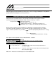
Safety Guide When designing and manufacturing a robot system, ensure safety by following the safety Guides provided below and taking the necessary measures. Regulations and Standards Governing Industrial Robots Safety measures on mechanical devices are generally classified into four categories under the International Industrial Standard ISO/DIS 12100, “Safety of machinery,” as follows: Safety measures Inherent safety design Protective guards --- Safety fence, etc.
Requirements for Industrial Robots under Ordinance on Industrial Safety and Health Work area Outside movement range Work condition Cutoff of drive source During automatic operation Not cut off Cut off (including stopping of operation) Inside movement range Measure Signs for starting operation Installation of railings, enclosures, etc. Article Article 104 Article 150-4 Sign, etc.
Applicable Models of IAI’s Industrial Robots Machines meeting the following conditions are not classified as industrial robots according to Notice of Ministry of Labor No. 51 and Notice of Ministry of Labor/Labor Standards Office Director (Ki-Hatsu No.
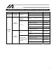
Notes on Safety of Our Products Common items you should note when performing each task on any IAI robot are explained below. No. Task 1 Model selection 2 3 4 Note This product is not planned or designed for uses requiring high degrees of safety. Accordingly, it cannot be used to sustain or support life and must not be used in the following applications: [1] Medical devices relating to maintenance, management, etc.
No. Task 4 Installation/ startup 5 Teaching Note (2) Wiring the cables Use IAI’s genuine cables to connect the actuator and controller or connect a teaching tool, etc. Do not damage, forcibly bend, pull, loop round an object or pinch the cables or place heavy articles on top. Current leak or poor electrical continuity may occur, resulting in fire, electric shock or malfunction. Wire the product correctly after turning off the power.
No. Task 6 Confirmation operation 7 Automatic operation 8 Maintenance/ inspection 9 Modification 10 Disposal Note After teaching or programming, carry out step-by-step confirmation operation before switching to automatic operation. When carrying out confirmation operation inside the safety fences, follow the specified work procedure just like during teaching. When confirming the program operation, use the safety speed.
Indication of Cautionary Information The operation manual for each model denotes safety guides under “Danger,” “Warning,” “Caution” and “Note,” as specified below. Level Degree of danger/loss Symbol Danger Failure to observe the instruction will result in an imminent danger leading to death or serious injury. Danger Warning Failure to observe the instruction may result in death or serious injury. Warning Caution Failure to observe the instruction may result in injury or property damage.
Handling Precautions 1. Handling the Actuator Unit 1.1 Handling the Packed Actuator Unless otherwise specified, the actuator of single-axis configuration is packed individually and shipped. When transporting or handling the packed actuator, exercise due caution not to hit the package against other object or drop the package. If the packed actuator is to be let stand for a while, place it on a flat floor. Do not step onto the package.
2. Handling the Actuator Assembly Pay attention to the following instructions when transporting the assembled actuator axes. 2.1 When Shipped Pre-assembled from IAI The specified machine assembly has been assembled by IAI, subjected to shipping test, and then packed inside a frame driven by nails onto a base of square timbers. If the combined actuator unit is of slider type, the slider is secured during packaging so that it will not move accidentally during transport.
Table of Content 1. Names of the Parts ................................................................................................1 2. External Dimensions ..............................................................................................3 2.1 2.2 ZR-S................................................................................................................................ 3 ZR-M ........................................................................................................
11. Operation Adjustment ..........................................................................................27 11.1 11.2 11.3 12. Notes on Operation ..............................................................................................29 12.1 12.2 12.3 13. About Brake ............................................................................................................... 29 About Home Return (Incremental Type) ..................................................................
1. Names of the Parts Z-axis stopper Ball screw spline shaft R-axis (Rotational axis) Z-axis, R-axis (Motor cable, encoder cable) Z-axis (Vertical axis) Cover Mounting flange Mounting hole 4 locations, tap size ZRS: M6, ZRM: M8 Positioning pin hole 2 locations Hole diameter 6H7 (+0.
Coordinate system Z-axis (vertical axis): The downward direction represents the positive direction. R-axis (rotational axis): The clockwise direction as viewed from the bottom represents the positive direction.
2. ZR-S 4 (Mechanical end) 2.1 External Dimensions 4-6.
35 B-B section 11 (inner diameter) 16h7 Detail View of Tip 4
ZR-M 5 (Mechanical end) 2.
44 B-B section 14 (inner diameter) 20h7 Detail View of Tip 6
3. Accessories Brake box [4] Actuator 1 Connector [5] Actuator 2 Connector [6] Controller 1 Connector [7] Controller 2 Connector 4-5 Note: The BK1 and BK2 switches are not available for a 24-V brake.
[1] 24-V power connector This connector is used to supply 24-V power to the external brake box. Applicable cable Terminal AWG28~16 +24-V power input GND 24 V 0V [2] Power ON LED The LED becomes lit when +24-V power is supplied to the external brake box. [3] External switch connector The brake can be forcibly released by connecting a switch to the external switch connector and then shorting pins 1 and 2. Cable-end connector 1 2 Terminal * XAP-02V-1 (Contact: BXA-001T-P0.
4. 4.1 Options Flanges Use a flange to install a work at the tip of the Z-axis. ZR-S flange: IX-FL-2 ZR-M flange: IX-FL-1 44 20 35 16 M5 25h7 60 34h7 70 4-5.5 4-5.5 50 5H7 5H7 60 +0.012 0 25 0.
4.2 Absolute Reset Adjustment Jigs These jigs are used if an absolute reset is required due to loss of absolute encoder data. * For the absolute reset adjustment procedure, refer to the operation manual for the controller (XSEL-P/Q). * The size is different between the ZR-S and ZR-M types.
5. Cable Drawings 5.1 Types of Encoder Cables Different encoder cables are used for the absolute encoder and incremental encoder types. Incremental type Be sure to use the LS type encoder cable (CB-X1-PLA) for the R-axis. Absolute type Either the normal type (CB-X1-PA) or LS type (CB-X1-PLA) can be used. 5.
5.3 Motor cable * Enter the applicable cable length (L) in . A desired length up to 30 m can be specified. Example) 080 = 8 m Model CB-X-MA (Front view) (Front view) Controller end 6. Wire size Actuator end Color Signal Signal Red Red White White Black Black Green Product Check Check the condition of the unpacked product as well as the included items. No. Item 1 Actuator Accessories 2 Brake box 3 Brake box-controller connection cable 4 Operation manual 6.1 No.
6.2 How to Read Model Nameplate Model Serial number 6.
7.
8. 8.1 Installation Environment, Storage Environment Installation Environment Install the unit in an environment meeting the conditions listed below. Not be exposed to direct sunlight. Be free from irradiating heat coming from a heat treatment furnace or other equipment that generates a large amount of heat. Have surrounding air temperature of 0 to 40°C. Have humidity of 85% or below (non-condensing). Be free from corrosive or flammable gases.
9. 9.1 Installation Installation of the Unit Each mounting flange has mounting holes (refer to "Names of the Parts"). Install the flange using the specified screws. Type Specified screw ZR-S ZR-M M6 M8 * Recommended tightening torque Bearing surface: Aluminum 536 Ncm 1,148 Ncm * Hexagonal socket head bolt of strength category 10.9 9.2 Actuator Installation Posture This actuator is of vertical type (= the ball screw is oriented vertically). It cannot be used in the horizontal direction.
9.3 Installation of Tool and Load (1) Installing the tool The tool mounting part must have sufficient strength and rigidity, along with adequate fastening power to prevent positional shift. It is recommended that a tool be installed over a split ring, power lock or other appropriate part. (The flanges specified in 4, "Options" are available.) To set the rotating direction using the D-cut surface and setscrews, be sure to use setscrews with resin or brass pad or set pieces made of soft material.
(2) Conditions of transferring load Transferring mass Type ZR-S ZR-M Rated transferring mass 1 kg 2 kg Maximum transferring mass 3 kg 6 kg Allowable load inertial moment Type Allowable inertial moment ZR-S 0.015 kgm2 ZR-M 0.03 kgm2 Remarks Maximum value * If the load inertial moment exceeds one-third of the allowable inertial moment, vibration may occur depending on the operating conditions. In this case, adjust the acceleration to a lower level.
9.4 Installation of User Components Tapped holes are provided on the side faces of the unit for installing user components. [Refer to 1, "Names of the Part."] Use these holes to install brackets for jigs or sensors provided by the user. [For the detailed dimensions, refer to 2, "External Dimensions."] Type Tap size Effective depth * Recommended tightening torque Bearing surface: Aluminum * Recommended tightening torque Bearing surface: Steel ZR-S ZR-M M4 12 mm 176 Ncm {18.0 kgfcm} 359 Ncm {36.
10. Wiring 10.
10.2 Wiring Diagram (Absolute) Brake box-controller connection cable (supplied) Brake box Encoder cable Encoder cable The LS connector is not connected.
10.3 Wiring Method (1) Determine the control axis number (Axis No.) of each actuator according to the system (program) and connect the actuator to the corresponding connector on the controller. Encoder cable connector Display on Control axis number controller front (Axis No.) panel 1 PG1 2 PG2 3 PG3 4 PG4 5 PG5 6 PG6 Motor cable connector Display on Control axis number controller front (Axis No.
(3) Connect a 24-VDC power supply to the brake box and controller and supply the power. Brake box Controller (with brake) 24-VDC power input 24-VDC power input Caution: Before connecting each cable/connector, confirm that the connector pins are not bent or broken and the cable is not damaged, and then plug in the connector firmly. When connecting the encoder cable, be sure to confirm the orientation of the connector first.
10.4 Prohibited Wiring Practices Connect the connector at the end of the cable, to the controller. For the connection methods of the I/O cable, controller power cable, PC connection cable, etc., refer to the operation manuals for your controller and PC software. When designing an application system using actuators and controllers, incorrect wiring or connection of each cable may cause unexpected problems such as a disconnected cable or poor contact. This section explains prohibited handling of cables.
Do not pinch, drop a heavy object onto or cut the cable. When fixing the cable, provide a moderate slack and do not tension it too tight. Do not use a spiral tube where the cable flexes frequently. 10.5 Notes on Use of Cable Track The supplied cables are not robot cables. Accordingly, never store the cables in a cable track. Always use a robot cable for each relay cable. Use a cable track with a bending radius (r) of 50 mm or more.
Do not let the cable got tangled or kinked in a cable track or flexible tube. Do not bundle the cables to allow a certain degree of flexibility (so that the cable will not become too taut when bent). Do not cause the cables to occupy more than 60% of the space in the cable track. Cable track Cable 10.6 Wiring in the Duct Separate the I/O and communication lines from the power and drive lines. Do not guide them together in the duct. Power line Duct Signal lines (flat cable etc.) 10.
11. Operation Adjustment 11.1 Guide for Acceleration Setting When setting the acceleration, use the following graph as a guide. This graph provides a guide when each axis is operated separately. If interpolated operation is performed, adjust the acceleration according to the acceleration/deceleration of the slower axis. Continuous operation (duty: 100%) Refer to 11.2, "Notes on Transferring Load.
11.2 Notes on Transferring Load Set an appropriate acceleration according to the mass and inertial moment at the tip. Failure to do so may result in premature consumption of life, damage or vibration of drive parts. If vibration occurs, lower the acceleration. To raise the acceleration, adjust it to an appropriate level by gradually raising the set value. If the load gets offset, the unit becomes more likely to cause vibration.
12. Notes on Operation 12.1 About Brake The brake is provided to retain the load in position should the servo turn off for some reason. It cannot be used as an emergency stop brake. Loads equivalent to or heavier than the maximum loading capacity cannot be retained. (For the maximum loading capacity, refer to 7, "Specifications.") Use the brake release switch on the controller to release the brake manually. No brake release switch is provided on the robot side.
12.3 Position Gain If the position gain is different for each axis during CP operation (interpolated operation) involving an orthogonal axis and the Z-axis or R-axis of a ZR unit, the locus may be affected depending on the operating conditions. Accordingly, it is recommended that the same position gain be set for all axes. Adjust the position gain using Axis-specific Parameter No. 60 of your controller (XSEL-P/Q). For the method to change this parameter, refer to the operation manual for your PC software.
13. Maintenance and Inspection Daily and periodic inspections are needed to make sure the actuator you purchased can be used safely and efficiently. Perform the following maintenance and inspection items. 13.1 Inspection Intervals and Items These inspection intervals assume that the actuator is operated eight hours a day. If the utilization ratio is higher, such as when the actuator is operated continuously 24 hours a day, reduce the inspection intervals according to the operating hours.
13.2 Visual Inspection of Exterior Inspect the following items before and after operating the robot every day. Inspection location Safety feature installed by the user (safety cage, etc.) Robot Cables Emergency stop switches Inspection item Correct the cage for deformation or displacement. Operation of safety circuits Whether interlock mechanisms operate normally Looseness of robot installation bolts External abnormality (Check the cables for looseness, damage, dent, etc.
13.5 Greasing Greasing procedure for the R-axis (How to remove the cover) Shift the cover upward. Remove the hexagonal socket head bolts. M3 x 6, 4 pcs Loosen the cross-recessed countersunk head machine screws. M3 x 10, 6 pcs Cover Inner frame Install the cover so that it fits between the inner frame and rear panel. Apply grease on the R-axis gears. Remove the hexagonal socket head bolts. M3 x 6, 2 pcs Rear panel Loosen the cross-recessed countersunk head machine screws.
14. Appendix 14.1 Absolute Reset Method (Absolute Type Only) When the ZR unit is connected to the controller for the first time, an absolute encoder battery voltage error generates, or the encoder cable is removed, an encoder battery error will generate. In this case, an absolute reset is required. 14.1.1 Preparation for Absolute Reset Perform an absolute reset of the ZR unit from the ball screw spline adjustment menu of the PC software (or teaching pendant).
14.1.2 Starting the Absolute Reset Menu (Ball Screw Spline Adjustment Window) (1) Open the ball screw spline adjustment window in the PC software. (2) The ball screw spline adjustment window opens. When a linear movement axis number is selected, the “Rotational Movement Axis No. (Mating Axis No.)” and “Encoder Type” field appear. Ball screw spline adjustment is performed for the linear movement axis and rotational movement axis as a pair.
14.1.3 Absolute Reset (Ball Screw Spline Adjustment) Procedure (1) Select the “Linear Movement Axis No.” to implement an absolute reset (ball screw spline adjustment) for.
(3) When the dialog box appears, click the “Yes” button. (4) When the dialog box appears, click the “Yes” button.
(5) Click the “Reset Controller Error” button. (6) Click the “Servo ON (Linear Movement Axis, Rotational Movement Axis)” button.
(7) Click the "Wait in Tentative Reference Position (Linear Movement Axis)” Button. Exercise caution because the linear movement axis (Z-axis) will return home. (8) Jog the rotational movement axis (R-axis) to the reference position (see “Reference Position Drawing”), and then click the “End Jog” button.
(9) Click the “Servo OFF (Linear Movement Axis, Rotational Movement Axis)” button. (10) Press the emergency stop switch (emergency stop button on the PC cable). (11) Release the brake. Release the brake using the switch on the controller.
(12) Set the plate and pin constituting the adjustment jig as shown below to affix the axis in the reference position. D-cut surface d Shaft c a b c a d b Installation method [1] Insert the ball screw spline into the hole in the jig from below. [2] Cause the D-cut surface of the ball screw spline to contact surface a. [3] Cause the side face of the ball screw spline to surface b. [4] Tighten screw c to affix the jig on the ball screw spline.
(13) Click the “Confirm” button. (14) Click the “Reset Encoder Rotation Data 2 (Rotational Movement Axis)” button.
(15) When the dialog box appears, click the “Yes” button. (16) When the dialog box appears, click the “Yes” button.
(17) Click the “Auto Refresh of Home Preset (Required) (Rotational Movement Axis)” button. (18) (19) (20) (21) 44 Remove the adjustment jig. Lock the brake (on the front panel of the controller). Cancel the emergency stop (by releasing the emergency stop button on the PC cable). Click the “Confirm” button.
(22) Click the “Servo ON (Linear Movement Axis, Rotational Movement Axis)” button. (23) Click the “Wait in Reference Position (Linear Movement Axis) (Rotational Movement Axis 0)” button. ● Exercise caution because once the rotational movement axis (R-axis) moves to the zero point, the linear movement axis (Z-axis) will return home.
(24) Click the “Servo OFF (Linear Movement Axis, Rotational Movement Axis)” button. (25) Click the “Reset Encoder Rotation Data 3 (Linear Movement Axis)” button.
(26) When the dialog box appears, click the “Yes” button. (27) Click the “Auto Refresh of Home Preset (Required) (Linear Movement Axis)” button, and then click “x” in the top right-hand corner of the window to close the window. Warning Be careful not to deviate from the specified steps, because it may result in position deviation.
(28) When the ball screw spline adjustment window is closed after performing ball screw spline adjustment, the following screen appears. Click the “Yes” button. (29) When all data has been written to the flash ROM, the following screen appears. Click the “Yes” button.
15. Warranty The ZR-series robot you have purchased passed IAI's strict shipping inspection. The warranty information is provided below. (1) Warranty period One of the following periods, whichever expires first: 18 months after shipment from IAI 12 months after delivery to the specified location 2,500 hours of operation (2) Scope of warranty The warranty covers only the purchased and delivered IAI product.
16. Change History Revision Date January 2009 December 2009 April 2010 50 Description of Revision First edition Added 14, “Appendix” and 14.1, “Absolute Reset Method.” Added wiring diagrams for incremental and absolute specifications in 10, “Wiring.
Catalog No.: ME3668-3A Head Office: 2690 W. 237th Street, Torrance, CA 90505 TEL (310) 891-6015 FAX (310) 891-0815 Chicago Office: 1261 Hamilton Parkway, Itasca, IL 60143 TEL (630) 467-9900 FAX (630) 467-9912 Atlanta Office: 1220 Kennestone Circle, Suite 108, Marietta, GA 30066 TEL (678) 354-9470 FAX (678) 354-9471 website: www.intelligentactuator.com Ober der Röth 4, D-65824 Schwalbach am Taunus, Germany TEL 06196-88950 FAX 06196-889524 IAI (Shanghai) Co., Ltd.