
Switch User Manual


SmartConnect User’s Guide
44
Chapter 4: Stacking BMD00082, February 2009
Stacking Requirements
Before switch modules can form a stack, they must meet the following requirements:
All switches must be the same type.
All blade server chassis must be the same type or have the same number of server slots
(for example, BCE and BCH chassis types are compatible for stacking).
Each switch must be installed with VSE SmartConnect software. The same release version
is not required, as the Master switch will push a firmware image to each differing switch
in the stack.
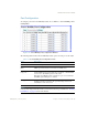
It is recommended that two 10Gb external ports on each switch are dedicated to stacking.
External ports 17 and 18 are used by default, though this can be changed during configura-
tion if necessary. The cables used for connecting the switches in a stack carry low-level,
inter-switch communications critical to shared switching functions. Always maintain the
stability of stack links in order to avoid internal stack reconfiguration.
Stack Membership
A stack contains up to eight switches, interconnected by a stack trunk in a ring topology. With
this topology, only a single stack link failure will be allowed. The stack contains one Master
and one or more Members, as follows:
Master
One switch controls the operation of the stack and is called the Master. The Master provides a
single point to manage the stack. A stack must have one and only one Master. Firmware image,
configuration information, and run-time data are kept by the Master and pushed to each switch
in the stack.
Member
Member switches can reside within a single blade server chassis or across multiple chassis.
Members receive configuration changes, run-time information, and software updates from the
Master.
Backup
One member switch can be designated as a Backup to the Master. The Backup takes over con-
trol of the stack if the Master fails. Configuration information and run-time data are synchro-
nized with the Master.