IBM Mobile Systems ThinkPad 310, 310D, 310E, 310ED Hardware Maintenance Manual February 1998 S05L-1935-00
IBM Mobile Systems ThinkPad 310, 310D, 310E, 310ED Hardware Maintenance Manual February 1998 IBM S05L-1935-00
Note Before using this information and the product it supports, be sure to read the general information under “Notices” at the back of this manual.
About This Manual This manual contains service and reference information for IBM ThinkPad 310, 310D, 310E or 310ED (2600) products. Use this manual along with the advanced diagnostic tests to troubleshoot problems effectively. The manual is divided into sections as follows: The Introduction section provides general information, guidelines, and safety information required to service computers. The product-specific section includes service, reference, and product-specific parts information.
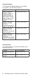
Related Publications The following mobile product publications are available through IBM or your IBM Authorized Dealer.
Contents Introduction . . . . . . . . . . . . . . . . . . . How to Use Error Messages . . . . . . . . . . How to Read POST Error Messages . . . . . . Safety Notices (Multi-lingual Translations) . . . . . Safety Information . . . . . . . . . . . . . . . . General Safety . . . . . . . . . . . . . . . . Electrical Safety . . . . . . . . . . . . . . . Safety Inspection Guide . . . . . . . . . . . Handling Electrostatic Discharge-Sensitive Devices Grounding Requirements . . . . . . . . . . . .
vi IBM Mobile Systems ThinkPad 310 (D/E/ED) HMM
Introduction Important Diskette fixes are customer installable. The diskette fixes are located on the PC Company Bulletin Board Service (BBS). The direct phone line for modem connection is 919-557-0001 or tieline 255-0001. Advise customers to contact the PC Company HelpCenter at 800-772-2227 if they need assistance in obtaining or installing any diskette fixes. Customers in Canada should call IBM HelpPC at 800-565-3344 for assistance or down-load information.
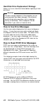
Hard Disk Drive Replacement Strategy: Always try to run a low-level format before replacing a hard disk drive. Attention The drive startup sequence in the computer you are servicing might have been changed. Be extremely careful during write operations such as copying, saving, or formatting. Data or programs can be overwritten if you select an incorrect drive. How to Use Error Messages Use the error codes displayed on the screen to diagnose failures.
Safety Notices (Multi-lingual Translations) In this manual, safety notices appear in English with a page number reference to the appropriate multi-lingual, translated safety notice found in this section. The following safety notices are provided in English, French, German, Italian, and Spanish languages. Safety Notice 1 Before the computer is powered-on after FRU replacement, make sure all screws, springs, or other small parts are in place and are not left loose inside the computer.
Safety Notice 2 Some standby batteries contain a small amount of nickel and cadmium. Do not disassemble it, recharge it, throw it into fire or water, or short-circuit it. Dispose of the battery as required by local ordinances or regulations. Use only the battery in the appropriate parts listing. Use of an incorrect battery can result in ignition or explosion of the battery. Certaines batteries de secours contiennent du nickel et du cadmium.
Safety Notice 3 The battery pack contains small amounts of nickel. Do not disassemble it, throw it into fire or water, or short-circuit it. Dispose of the battery pack as required by local ordinances or regulations. Use only the battery in the appropriate parts listing when replacing the battery pack. Use of an incorrect battery can result in ignition or explosion of the battery. La batterie contient du nickel. Ne la démontez pas, ne l'exposez ni au feu ni à l'eau. Ne la mettez pas en court-circuit.
Safety Notice 4 The lithium battery can cause a fire, explosion, or severe burn. Do not recharge it, remove its polarized connector, disassemble it, heat it above 100°C (212°F), incinerate it, or expose its cell contents to water. Dispose of the battery as required by local ordinances or regulations. Use only the battery in the appropriate parts listing. Use of an incorrect battery can result in ignition or explosion of the battery. La pile de sauvegarde contient du lithium.
Safety Notice 5 If the LCD breaks and the fluid from inside the LCD gets into your eyes or on your hands, immediately wash the affected areas with water for at least 15 minutes. Seek medical care if any symptoms from the fluid are present after washing. Si le panneau d'affichage à cristaux liquides se brise et que vous recevez dans les yeux ou sur les mains une partie du fluide, rincez-les abondamment pendant au moins quinze minutes. Consultez un médecin si des symptômes persistent après le lavage.
Safety Notice 6 To avoid shock, do not remove the plastic cover that surrounds the lower portion of the inverter card. Afin d'éviter tout risque de choc électrique, ne retirez pas le cache en plastique protégeant la partie inférieure de la carte d'alimentation. Aus Sicherheitsgründen die Kunststoffabdeckung, die den unteren Teil der Spannungswandlerplatine umgibt, nicht entfernen. Per evitare scosse elettriche, non rimuovere la copertura in plastica che avvolge la parte inferiore della scheda invertitore.
Safety Notice 8 Before removing any FRU, power-off the computer, unplug all power cords from electrical outlets, remove the battery pack, then disconnect any interconnecting cables. Avant de retirer une unité remplaçable en clientèle, mettez le système hors tension, débranchez tous les cordons d'alimentation des socles de prise de courant, retirez la batterie et déconnectez tous les cordons d'interface.
Safety Information The following section contains the safety information that you need to be familiar with before servicing an IBM mobile computer. General Safety Follow these rules to ensure general safety: xvi Observe good housekeeping in the area of the machines during and after maintenance. When lifting any heavy object: 1. Ensure you can stand safely without slipping. 2. Distribute the weight of the object equally between your feet. 3. Use a slow lifting force.
Electrical Safety Observe the following rules when working on electrical equipment. Important Use only approved tools and test equipment. Some hand tools have handles covered with a soft material that does not insulate you when working with live electrical currents. Many customers have, near their equipment, rubber floor mats that contain small conductive fibers to decrease electrostatic discharges. Do not use this type of mat to protect yourself from electrical shock.
Regularly inspect and maintain your electrical hand tools for safe operational condition. Do not use worn or broken tools and testers. Never assume that power has been disconnected from a circuit. First, check that it has been powered-off. Always look carefully for possible hazards in your work area. Examples of these hazards are moist floors, nongrounded power extension cables, power surges, and missing safety grounds.
The guide consists of a series of steps presented in a checklist. Begin the checks with the power off, and the power cord disconnected. Checklist: 1. Check exterior covers for damage (loose, broken, or sharp edges). 2. Power-off the computer. Disconnect the power cord. 3. Check the power cord for: a. A third-wire ground connector in good condition. Use a meter to measure third-wire ground continuity for 0.1 ohm or less between the external ground pin and frame ground. b.
Handling Electrostatic Discharge-Sensitive Devices Any computer part containing transistors or integrated circuits (ICs) should be considered sensitive to electrostatic discharge (ESD). ESD damage can occur when there is a difference in charge between objects. Protect against ESD damage by equalizing the charge so that the machine, the part, the work mat, and the person handling the part are all at the same charge. Notes 1. Use product-specific ESD procedures when they exceed the requirements noted here. 2.
Laser Compliance Statement Some IBM Personal Computer models are equipped from the factory with a CD-ROM drive. CD-ROM drives are also sold separately as options. The CD-ROM drive is a laser product. The CD-ROM drive is certified in the U.S. to conform to the requirements of the Department of Health and Human Services 21 Code of Federal Regulations (DHHS 21 CFR) Subchapter J for Class 1 laser products.
El uso de controles o ajustes o la ejecución de procedimientos distintos de los aquí especificados puede provocar la exposición a radiaciones peligrosas. Opening the CD-ROM drive could result in exposure to hazardous laser radiation. There are no serviceable parts inside the CD-ROM drive. Do not open. Some CD-ROM drives contain an embedded Class 3A or Class 3B laser diode. Note the following. DANGER: Laser radiation when open.
ThinkPad 310, 310D, 310E, 310ED (2600) Read This First Before you go to the checkout guide, be sure to read this section. Important Notes Only certified, trained personnel should service the computer. Read FRU service procedures before replacing any FRUs. Be extremely careful during write operations such as copy, saving or formatting. Drives in the computer that you are servicing might have been rearranged or the drive startup sequence might have been altered.
___1. ___2. ___3. ___4. ___5. ___6. ___7. ___8. ___9. Name and phone number of servicer. Date of service. Date when part failed. Date of purchase. Failure symptoms, error codes appearing on display, and beep symptoms. Procedure index and page number in which failing FRU was detected. Failing FRU name and part number. Machine type, model number, and serial number. Customer's name and address.
Important If the following symptoms are present, they may indicate damage caused by non-warranted activity: Missing parts may be a symptom of unauthorized service or modification. HDD spindles can become noisy if subjected to excessive force or by being dropped. How to Disable the Power-On Password: To clear a password from the system, first identify the password switch by referring to “Switch Locations” on page 68, then follow the steps below. 1. Power-off the computer. 2.
2. Verify the symptoms by attempting to re-create the failure by running the diagnostic test or by repeating the same operation. 3. Use the following table with the verified symptom to determine which page to go to. Search the symptoms column and find the description that best matches your symptom; then go to the page shown in the “Go to” column. Symptoms (Verified) Go to Power failure. (The power indicator does not go on or stay on.) “Power System Checkout” on page 8. POST does not complete.
2. Boot from the diagnostics diskette and start the PQA program (refer to “Running PQA Diagnostics Program” on page 25). 3. Select the Memory item to run the memory test. If no error appears, install a new DIMM; if an error appears, replace the system board. System Programs in Flash Memory: System setup programs are stored in flash memory. Flash Memory Update: A flash memory update is required for the following conditions: New versions of system programs. New features or options are added.
1. Boot from the diagnostics diskette and start the PQA program (please refer to “Running PQA Diagnostics Program” on page 25). 2. Go to the diagnostic menu screen; select Keyboard test and press F2 in the test items. 3. Check that when each key is pressed, the key's position on the keyboard layout on the screen changes to a black square. Note: Press Y+Enter to exit the test. If the tests detect a keyboard problem, do the following one at a time to correct the problem. Do not replace a non-defective FRU.
has exceeded its normal temperature range. This symptom does not indicate a hardware problem. No service actions are necessary if the pointer movement stops in a short period of time. If a click button problem or pointing stick problem occurs, do the following: 1. Boot from the diagnostics diskette and start the PQA program (please refer to “Running PQA Diagnostics Program” on page 25). 2. Go to the diagnostic Manual Test menu. 3. Press F2 in the test items. 4. Press the left and right click buttons. 5.
3. Replace the diskette drive flexible cable. 4. Replace the system board. If an error occurs when the external diskette drive is attached through the external diskette drive connector and there is no internal diskette drive, reseat the connector. If the error still remains, perform the following actions, one at a time. 1. Replace the external FDD cable. 2. Replace the diskette drive. 3. Replace the system board. CD-ROM Drive Test Do the following to isolate the problem to a controller, drive, or CD-ROM.
Checking the AC Adapter: You are here because the computer fails only when the AC Adapter is used. If the power-on indicator of the AC Adapter does not turn on, make sure of the following: Power cord is not damaged. Power cord is securely connected to the AC Adapter and AC power outlet. If the above confirmation does not solve the problem, replace the AC Adapter. If the power-on indicator of the AC Adapter is on, then proceed to the next step. 1.
Checking Operational Charging: To check operational charging, use a discharged battery pack or a battery pack that has less than 50% of the total power remaining when installed in the computer. Perform operational charging: 1. If the battery status indicator does not turn on, remove the battery pack and allow it to return to room temperature. 2. Reinstall the battery pack. If the charge indicator still does not turn on, replace the battery pack. Checking the Battery Pack: Do the following: 1.
BIOS Utility Your computer has a BIOS Utility that allows you to configure the computer and its hardware settings. Note: The computer is also bundled with a Windows 95based computer management utility similar in function to the BIOS Utility called the Notebook Manager. The computer is already correctly configured for you. If you make any changes to the computer or you receive an Equipment Configuration Error message (error code 246) after you power-on the computer, you need to run the BIOS Utility.
Navigating the BIOS Utility Screens From the main menu screen, press ↑ or ↓ to move from one menu item to another and press Enter to select a menu. Parameters displayed in low brightness (grayed-out) are not user-configurable. The computer detects and sets the values for these parameters. Press ↑ or ↓ to move from one parameter to another. Press ← or → to change parameter settings. You have to change some settings when you add a component to the computer.
hibernation file is not present or invalid). The battery power indicator blinks amber. Events that cause the computer to exit standby mode: The LCD is opened. The ring indicator (RI) is signaled by a serial or PCMCIA device. Any key or pointing device operation. Note: If the computer enters standby mode and the computer is using a communication or I/O PC Card, the PC Card and application program remain active.
Symptom-to-FRU Index The Symptom-to-FRU Index lists the symptoms and errors and the possible causes. The most likely cause is listed first. Note: Perform the FRU replacement or actions in the sequence shown in the FRU/Action columns. If a FRU did not solve the problem, put the original part back in the computer. Do not replace a non- defective FRU. This index can also be used to help you decide which FRUs to have available when servicing a computer.
Error Code Message 021 Keyboard Error or Keyboard Not Connected Note: The message only appears for a few seconds. 022 Keyboard Locked Note: The message only appears for a few seconds. 030 Pointing Device Error Note: The message only appears for a few seconds. 031 Pointing Device Interface Error Note: The message only appears for a few seconds. FRU/Action in Sequence 1. Go to “Keyboard and External Input Device Checkout” on page 5. 2. Ensure that the keyboard switch is correctly set. 3.
Error Code Message 047 Diskette Drive(s) Disabled 1. Ensure the diskette drive is not set to [Disabled] in the “System Security” of BIOS Utility. 2. Diskette drive cable 3. Diskette drive 048 Diskette Write Protected 1. Ensure the diskette drive is not set to [Write Protect All Sectors] in the “System Security” of BIOS Utility. 2. Diskette drive cable 3. Diskette drive 050 IDE Drive 0 Error 1. Ensure the hard disk 0 is set to [Auto] in the Basic System Settings of BIOS Utility. 2.
Error Code Message FRU/Action in Sequence 072 CMOS Checksum Error 1. Enter BIOS Utility to execute Load Setup Default Settings, then reboot system. 2. Backup battery (RTC battery) 3. System board 081 System Resource Conflict 1. Enter BIOS Utility to execute Load Setup Default Settings, then reboot system. 2. Remove the non-factory-installed adapter card and reboot system. 082 IRQ Setting Error 1. Enter BIOS Utility to execute Load Setup Default Settings, then reboot system. 2.
No Beep Symptoms Symptom/Error FRU/Action in Sequence No beep, poweron indicator on, and a blank LCD during POST 1. Ensure all connectors are securely seated. 2. Reseat the CPU 3. CPU 4. System board No beep, poweron indicator not on, and a blank LCD during POST 1. Reseat the LCD Connectors 2. Power source (battery & adapter). See “Power System Checkout” on page 8. 3. Audio connector board 4. Charger board 5. Hard disk drive 6. LCD inverter ID 7. LCD FPC Cable 8. LCD inverter 9. LCD 10.
Symptom/Error No beep, power-on indicator on, and a blank LCD during POST LCD backlight not working LCD too dark LCD brightness cannot be adjusted LCD contrast cannot be adjusted LCD screen unreadable Characters missing pels Screen abnormal Wrong color displayed LCD has extra horizontal or vertical lines displayed. FRU/Action in Sequence 1. 2. 3. 4. 5. 6. 7. 8. 9. Reseat the LCD Connectors. Hard disk connector board.
Indicator-Related Symptoms Symptom/Error Indicator incorrectly remains off or on, but system runs correctly FRU/Action in Sequence 1. Reseat the Audio connector board. 2. Audio connector board 3. System board Power-Related Symptoms Symptom/Error FRU/Action in Sequence Power shuts down during operation. 1. Go to “Power System Checkout” on page 8. 2. AC Adapter 3. Battery Pack 4. Battery connector board 5. Charger board 6. System board The system will not power-on. 1.
Speaker-Related Symptoms Symptom/Error Speakers have noise or no sound comes from system FRU/Action in Sequence 1. Chassis (speaker on chassis) 2. Audio connector board 3. System board Power Management-Related Symptoms Symptom/Error FRU/Action in Sequence The system will not enter hibernation. 1. Go to “Hibernation Mode” on page 13 and see the note. 2. Ensure the “System Hibernation Timer” in the Power Management Settings of BIOS Utility is not set to [OFF]. 3.
Symptom/Error FRU/Action in Sequence System hangs intermittently. 1. Hard disk/diskette/CD-ROM drive connector 2. Fan (go to “Running Fan Diagnostics Program” on page 29). 3. System board In DOS or Windows, multimedia programs, no sound comes from the computer. (Only system beeps are heard at power-on) 1. Go to “Audio Board Checkout” on page 6. 2. Audio connector board 3. Chassis (speaker on chassis) 4.
Undetermined Problems You are here because the diagnostic tests did not identify which adapter or device failed, installed devices are incorrect, a short circuit is suspected, or the system is inoperative. Follow the procedures below to isolate the failing FRU. Verify that the power supply being used at the time of the failure is operating correctly. 1. Power-off the computer. 2. Check the cables, wires, and connectors for short circuits and open circuits. Visually check them for damage.
Related Service Procedures This section provides information about the following: “Status Indicators.” “Power Switch” on page 25. “Running PQA Diagnostics Program” on page 25. “Fn Key Combinations” on page 30. Status Indicators The system status LED indicators show the current computer status in green and amber using symbols. The following shows the location of each symbol and the meaning of each indicator. Symbol Color Meaning .
Symbol Color Meaning .4/ Caps lock Green Indicates that the Caps Lock mode is enabled. All alphabetic characters (A- Z) are entered in capital letters without using the Shift key. The Caps Lock mode is enabled and disabled by pressing the Caps Lock key. .5/ Scroll lock Green Alternately turns on and off each time the ScrLk key is pressed. While this indicator is on, the Arrow keys are used as screen-scroll function keys. In this state, the cursor cannot be moved with the Arrow keys.
ThinkPad 310 Diagnostics Diskette (P/N 05L1936) ThinkPad 310 Maintenance Utility Diskette (P/N 05L1770) Boot from the Diagnostic Program Diskette and select PQA System Diagnostics Program from PC DOS 7.0 Startup Menu, the PQA main menu appears on screen. Press → or ← to move around the main menu. Press Enter to enable the selected option. The main options are Diag, Result, SysInfo, Option and Exit. The Diag option lets you select testing items and times.
Auto Test Performs multiple tests of the selected items and checks the selected test items in sequence. Note: PCMCIA Diagnostic supports manual test only. Do not select PCMCIA Diagnostic in Auto Test. The screen below appears if you select AUTO Test. Specify the desired number of tests and press Enter. After you specify the number of tests to perform, the screen shows a list of test items (see below). Press ↑or ↓ to move the highlight bar from one item to another.
Space Esc F1 F2 Enter Test Times Enables/disables the item Exits the program Help Tests the selected item(s) Opens the available suboptions Indicates the number of tests to perform. Note: The F1 and F2 keys function only after you finish configuring the Test option. PC Test Card LED The green LED on the PC test card turns on when the PCMCIA test is running. If the LED does not turn on, check that the card is installed correctly by reseating the card.
Error Code Message FRU/Action in Sequence 10XXX CPU or System board error 1. CPU 2. System board 11XXX Pointing device error 1. TrackPoint board FPC cable 2. TrackPoint board 3. Keyboard 4. System board PCMCIA X XXXX PCMCIA error 1. Replace PC Card 2. PCMCIA slots assembly 3. System board Running Fan Diagnostics Program The system is equipped with sensors to protect against system overheating.
1. Boot from the Utility Program Diskette. 2. Select Thermal Sensor Utility from PC DOS 7.0 Startup Menu, then the system thermal is executed. Setting Inverter ID There is an EEROM in the inverter which stores its supported LCD type ID code. If you replace the LCD with a different brand, the ID information in the inverter EEROM should be updated. Follow the steps below to set the LCD Inverter ID: 1. Boot from the Utility Program Diskette. 2. Select Inverter ID Utility from PC DOS 7.0 Startup Menu. 3.
Fn + Description F61 Power Management Settings and System Information screens F72 Standby invocation F83 Hibernation invocation Right arrow Scale increase (used with Fn+F2, Fn+F5) Left arrow Scale decrease (used with Fn+F2, Fn+F5) Esc Hotkey Icon Escape ThinkPad 310, 310D, 310E, 310ED (2600) 31
Product Overview The following is an overview of the system features.
FRU Removals and Replacements This section contains information about removals and replacements. Do not damage any parts. Only certified and trained personnel should service the computer. The arrows in this section show the direction of movement to remove a FRU, or to turn a screw to release the FRU. The arrows are marked in numeric order, in square callouts, to show the correct sequence of removal.
Screw Type Example Explanation Illustration Size Head and Color M2 x 4L Flat head, black or silver M2 x 6L Pan head, black or silver M3 x 6L Bind head, black or silver Note: Some screws have nylock paste (on the grooves) for better friction and increased stability. Some screws have bracket supports. FPC Cable Connector Type Unplugging the Cable To unplug the cable, first unlock the connector by pulling up the two clasps on both sides of the connector with a plastic tool.
I/O Door Press the rear connector door latch to open the door. Remove the center latch; then remove the rear connector door by flexing it. Battery Pack and Battery Pack Door Reverse the steps above to install a battery pack.
Hard Disk Drive and Hard Disk Drive Door Turn the computer upside down. Step Size (Quantity) Head and Color .1/ M2 x 6L (1) Flat head, black Memo Note: Make sure you use the correct screw when replacing. Reverse the steps above to install a hard disk drive.
Warning: Do not drop or apply any shock to the hard disk drive. The hard disk drive is sensitive to physical shock. Incorrect handling can cause damage and permanent loss of data on the hard disk. Before removing the hard disk drive, have the user make a backup copy of all the information on the hard disk. Never remove the hard disk drive while the system is operating or is in hibernation mode.
DIMM and DIMM Door Turn the computer upside down. Step Size (Quantity) Head and Color .1/ M2 x 5L (1) Bind head, black Memo Note: The screw does not separate from the DIMM cover. Note: When installing the DIMM, do the following: 1. Find the notch on the side of the DIMM. 2. With the notched end of the DIMM toward the right side of the socket, insert the DIMM, at an angle of approximately 20° , into the socket; then press it firmly. 3. Pivot the DIMM until it snaps into place.
Side View Hinge Cover ThinkPad 310, 310D, 310E, 310ED (2600) 39
Step Size (Quantity) Head and Color .1/ M2 x 4L (4) Flat head, black Memo Note: Make sure you use the correct screw when replacing.
Keyboard Hinge Covers (5) When replacing the keyboard unit, connect the keyboard connector as shown in the figure; then replace the keyboard. (The leftmost and rightmost connectors should be unlocked by lifting the clasps from under them. Unlock the center connector by pulling on the left and right of the clasp.) Warning: Hold down the keyboard connection board when pulling out the cables, so as not to damage the cables.
Thermal Plate/CPU Hinge Covers (5) Keyboard Unit (6) Step Size (Quantity) Head and Color .1/ M2.5 x 18L (4) Pan head, silver Memo Note: Make sure you use the correct screw when replacing. Note: For 310E/ED, machine type 2600-Axx/Bxx/Cxx/Dxx/Exx/Fxx model, a pad is found between the thermal plate and the PC Card slots. When reinstalling the thermal plate, first place the pad on top of the PC Card slots before you procceed. Installing CPU 1.
Important: A sponge pad is found underneath the CPU. When installing a replacement CPU, make sure the sponge pack is in place. If you need to replace the sponge pad, it is part of the mylar pack FRU.
Diskette Drive/CD-ROM Drive Hinge Covers (5) Keyboard Unit (6) Thermal plate / CPU (7) Important: When removing the module locks, pull them up at an angle. They cannot be removed when pulled straight up.
CD-ROM Drive (Model Unique) Warning: Do not open the CD-ROM; no user adjustments or serviceable parts are inside. Use of controls, adjustments, or the performance of procedures other than those specified may result in hazardous radiation exposure.
CAUTION: Do not push on the top surface of the CD-ROM drive. Note: For 310E/ED, machine type 2600-Bxx/Dxx model, you need to perform an extra step as shown in the illustration above. This step removes the CD-ROM drive cable before you pull out the CD-ROM drive.
LCD Removal and Replacement Hinge Covers (5) LCD Display Module Step Size (Quantity) Head and Color .1/ M2 x 5L (2) Pan head, Yellow Zn .2/ M2.5 x 8L (4) Pan head, silver Memo w/ nylock paste Note: Make sure you use the correct screw when replacing.
LCD Bezel: Note: When removing the LCD, take note of the following: 1. Be careful not to scratch the LCD cover when removing the screw covers. 2. The LCD cover has several latches. Release these latches; then remove the LCD cover. Be careful not to break the latches. Step Size (Quantity) Head and Color Memo .2/ M2.5 x 6L (3) Pan head, black w/ nylock paste Note: Make sure you use the correct screw when replacing.
LCD, LCD Cover, LCD FPC Cable, LCD Left Hinge, and Inverter: Important: After you replace the LCD or inverter, follow the instructions in “Setting Inverter ID” on page 30. Note: For DSTN LCDs, a tape is used to secure the LCD FPC cable after it is connected to the LCD. This tape is a special tape with safety characteristics, and is part of the Mylar FRU. Removing Procedures: Remove LCD: .1/→.2/→.3/ Remove Inverter: .1/→.2/→.3/→.4/ →.5/ Remove Left Hinge: .6/→.7/ Remove LCD FPC cable: .1/→.2/→.3/→.4/ →.5/→.
LCD Right Hinge and LCD Diaper Step Size (Quantity) Head and Color Memo .1/ M2.5 x 6L (2) Pan head, black w/ nylock paste Note: Make sure you use the correct screw when replacing.
Inside Assembly Hinge Covers (5) Keyboard Unit (6) LCD Unit (9) Thermal plate and CPU (7) Upper Base Step Size (Quantity) Head and Color .1/ M2.5 x 18L (3) Pan head, silver .2/ M2.5 x 6L (4) Pan head, black .3/ M2 x 4L (1) Flat head, black Memo w/ nylock paste Note: Make sure you use the correct screw when replacing.
TrackPoint Board, TrackPoint Button and TrackPoint Board FPC Cable Step Size (Quantity) Head and Color .1/ M2 x 4L (2) Pan head, silver Memo Note: Make sure you use the correct screw when replacing.
Fan Note: The tape used to secure the fan is not ordinary tape, but a special tape with safety characteristics. This tape is part of the Mylar FRU. If you need to replace the fan, besides the new fan, you need to get from the Mylar FRU the following: the tape mentioned above, two sponge strips to stick on the sides of the fan, and a double-sided adhesive tape to attach on the underside of the fan. Refer to the old fan. Warning: The fan cable should follow the path shown in the figure.
Audio Connector Board Warning: Take care in removing the audio connection board (see figure) to avoid damaging the LEDs.
Battery Connector Board Step Size (Quantity) Head and Color Memo .2/ M2.5 x 6L (2) Pan head, black w/ nylock paste Note: Make sure you use the correct screw when replacing.
Speaker and Cover Switch Cables 56 IBM Mobile Systems ThinkPad 310 (D/E/ED) HMM
Lower Base Important: To remove the chassis with the system board out of the lower base, the PCMCIA slot buttons should be upright then pushed in (.1/→.2/) before you begin this removal procedure.
Step Size (Quantity) Head and Color Memo .3/ M2.5 x 6L (2) Pan head, black w/ nylock paste .4/ M2 x 4L (2) Pan head, silver Note: Make sure you use the correct screw when replacing.
PCMCIA Door and PCMCIA Door Spring ThinkPad 310, 310D, 310E, 310ED (2600) 59
Charger Board Step Size (Quantity) Head and Color .1/ M2 x 4L (2) Pan head, silver Memo Note: Make sure you use the correct screw when replacing.
System Board: Important: After replacing the system board, follow the instructions in “Setting Thermal Sensor Threshold” on page 29. Step Size (Quantity) Head and Color Memo .1/ M2 x 4L (2) Pan head, silver .2/ M2 x 4L (2) Pan head, black w/ nylock paste .3/ M2 x 4L (2) Pan head, silver w/ brackets .4/ M2 x 4L (1) Pan head, silver Note: Make sure you use the correct screw when replacing.
Backup Battery: Warning: The backup battery is a lithium battery and can cause a fire, explosion, or severe burns. Do not charge it, heat it higher than 100 C (212 F), incinerate it, or expose its cell contents to water. Dispose of the battery as required by local ordinances or regulations. Use of an incorrect battery can result in ignition or explosion of the battery. Replacement batteries can be ordered from IBM or IBM authorized dealers.
Keyboard Connector Board ThinkPad 310, 310D, 310E, 310ED (2600) 63
PCMCIA Slot Assembly Step Size (Quantity) Head and Color Memo .1/ M2 x 14L (2) Pan head, silver w/ brackets Note: Make sure you use the correct screw when replacing.
Locations Front View .1/ .2/ .3/ .4/ .5/ .6/ LCD Indicator panel Speakers Power switch CD-ROM eject button CD-ROM drive (310E/310ED) or diskette drive (310/310E) .7/ Battery cover release latch .8/ Battery bay .9/ Personalization nameplate .1ð/ TrackPoint III .11/ LCD release latch .12/ Click buttons .13/ Hard disk drive bay .14/ Fn key .15/ Function keys .16/ PC Card eject buttons .
Bottom View .
Rear View .1/ I/O door .2/ Power jack .3/ Security keyhole .4/ Microphone-in jack .5/ Line-in jack .6/ External diskette drive connector .7/ Line-out/headphone jack .8/ Serial connector .9/ Parallel connector .1ð/ External display connector .
Switch Locations There are two switches on the system board. CPU speed Keyboard select, password enable/disable and BIOS screen select and another switch on the DC-DC converter. CPU voltage Refer to the figure and tables below on how to set these switches. CPU Settings CPU Type Voltage Speed Intel P54CSLM-133 CPU 3.1V 133MHZ Intel P55C-133 CPU, MMX 2.45V 133MHZ Intel P55C-150 CPU, MMX 2.45V 150MHZ Intel P55C-166 CPU, MMX 2.45V 166MHZ CPU Voltage (S1) Settings CPU Voltage 2.
CPU Speed (SW3) Settings CPU Speed 133MHz 150MHz 166MHz Switch 1 On Off On Switch 2 Off On Off Switch 3 Off On On Switch 4 On On On Keyboard Language (SW2, Switch 1 and 2) Settings Keyboard Language European U.S.
310 - System Unit Parts Listing 70 IBM Mobile Systems ThinkPad 310 (D/E/ED) HMM
310D - System Unit Parts Listing ThinkPad 310, 310D, 310E, 310ED (2600) 71
310/310D - System Unit FRU List No. Description FRU No.
No. Description FRU No.
No. Description FRU No.
310/310D LCD Unit Parts Listing No. Description FRU No. Q'ty 1 11.3" DSTN/TFT LCD bezel (with logo) 11J8576 1 2 11.3" DSTN LCD 11J8593 1 11.3" TFT LCD 11J8594 1 3 LCD hinge (R) 11J8652 1 4 LCD inverter (DSTN/TFT) 11J8589 1 5 11.3" DSTN LCD FPC cable (with LCD cable diaper) 11J8577 1 11.
No. Description FRU No. Q'ty 7 11.3" DSTN LCD cover (with logo and LCD diaper and left hinge) 11J8573 1 11.
310E System Unit Parts Listing ThinkPad 310, 310D, 310E, 310ED (2600) 77
310ED System Unit Parts Listing 78 IBM Mobile Systems ThinkPad 310 (D/E/ED) HMM
310E/310ED System Unit FRU List No. Description FRU No.
No. Description FRU No.
No. Description FRU No.
310E/310ED LCD Unit Parts Listing 82 IBM Mobile Systems ThinkPad 310 (D/E/ED) HMM
310E/310ED LCD Module FRU list No. Description FRU No. Q'ty 1 11.3" TFT LCD bezel (with logo) 11J8576 1 2 11.3" TFT LCD 11J8594 1 12.1" DSTN LCD 12J0492 1 3 LCD hinge (R) 11J8652 1 4 LCD inverter 11J8589 1 5 11.3" TFT LCD FPC cable (with LCD cable diaper) 11J8578 1 12.1" DSTN LCD FPC cable (with LCD cable diaper) 12J0493 1 6 See Miscellaneous/ Mylar pack 7 11.3" TFT LCD cover (with logo and LCD diaper and left hinge) 11J8574 1 12.
310E (2600-Axx/Cxx/Exx/Fxx) System Unit Parts Listing 84 IBM Mobile Systems ThinkPad 310 (D/E/ED) HMM
310ED (2600-Bxx/Dxx) System Unit Parts Listing ThinkPad 310, 310D, 310E, 310ED (2600) 85
310E/310ED (2600-Axx/Bxx/Cxx/Dxx/Exx/Fxx) System Unit FRU List No. Description FRU No.
No. Description FRU No.
No. Description FRU No. Q'ty 26 2.1GB hard disk drive module assembly 05K8881 1 2.1GB hard disk drive module assembly (2600-Exx) 11J8625 1 3.
310E/310ED LCD Unit Parts Listing No. Description FRU No. Q'ty 1 12.1" DSTN LCD bezel (with logo) 12J0494 1 12.1" TFT LCD bezel (with logo) 05K4863 1 11.3" TFT LCD bezel (with logo) (2600-EXX) 11J8576 1 12.1" DSTN LCD 12J0492 1 12.1" TFT LCD 05J9338 1 11.
No. Description FRU No. Q'ty 5 12.1" DSTN LCD FPC cable (with LCD cable diaper) 12J0493 1 12.1" TFT LCD FPC cable (with LCD cable diaper) 05K2647 1 11.3" TFT LCD FPC cable (with LCD cable diaper) (2600-EXX) 11J8578 1 6 See Miscellaneous/ Mylar pack 7 12.1" DSTN LCD cover (with logo and LCD diaper and left hinge) 12J0495 1 12.1" TFT LCD cover (with logo and LCD diaper and left hinge) 05K4864 1 05K5231 1 12J0527 1 11.
310/310E/310D/310ED Miscellaneous and Other Parts Miscellaneous Item Description FRU No. Q'ty Misc. Parts Pack 1 Foot (long) 12J0515 2 Misc. Parts Pack 2 Misc.
Item Description FRU No. Q'ty Mylar pack 11.3" DSTN LCD diaper 05K4881 1 92 11.3" TFT LCD diaper 1 12.1" DSTN LCD diaper 1 12.
Item Description FRU No. Q'ty Screw pack M2 x 3L, Pan head, silver 11J8580 5 M2 x 4L, Flat head, black 5 M2 x 4L, Pan head, silver 5 M2 x 4L, Pan head, black, w/ nylock 5 M2 x 6L, Flat head, black 5 M2 x 6L, Pan head, silver 5 M2 x 14L, Pan head, silver 5 M2.5 x 6L, Pan head, black, w/ nylock 10 M2.5 x 8L, Pan head, silver, w/ nylock 5 M2.
Others Description FRU No.
Notices References in this publication to IBM products, programs, or services do not imply that IBM intends to make these available in all countries in which IBM operates. Any reference to an IBM product, program, or service is not intended to state or imply that only that IBM product, program, or service may be used.
IBM Part Number: 05L1935 Printed in U.S.A.