MODEL: IBM-412CID ADVANCED HOME/OFFICE 4 LINE TELEPHONE WITH CALLER-ID INSTALLATION AND OPERATION GUIDE Please read this manual carefully prior to installing your telephone.
TABLE OF CONTENTS IMPORTANT SAFETY INSTRUCTIONS ...............................................................................................5 BATTERY CAUTIONARY INSTRUCTIONS .........................................................................................6 GETTING STARTED ..................................................................................................................................7 Package Contents ...............................................................................
Adjusting the Headset Volume ..................................................................................................................23 Making an Outgoing Call Using the Headset .............................................................................................24 Answering an Incoming Call ......................................................................................................................24 INTERCOM .......................................................................
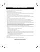
IMPORTANT SAFETY INSTRUCTIONS Before using your telephone equipment, basic safety precautions should always be followed to reduce the risk of fire, electrical shock and injury to persons, including the following: • Read and understand all instructions. • Follow all warnings and instructions marked on the product. • Unplug this product from the wall telephone jack and power outlet before cleaning. Do not use liquid cleaners or aerosol cleaners. Use a damp cloth for cleaning.
BATTERY CAUTIONARY INSTRUCTIONS BATTERIES: CAUTION • Use only 1.5 volt, AA-size batteries, (15A) carbon or alkaline batteries. (batteries not included.) • Do not dispose of the batteries in a fire. The cells may explode. Check with local codes for possible special disposal instructions. • Do not open or mutilate the batteries. Released electrolyte is corrosive and may cause damage to the eyes or skin. It may be toxic if swallowed.
GETTING STARTED PACKAGE CONTENTS 1. Check to be sure that you have all the following components in the package: 2. Telephone base. 3. Handset. 4. Headset. 5. Normal telephone line cord (2 pc’s). 6. Short telephone line cord. 7. Handset coiled cord. 8. Handset “Y” adapter. 9. AC power adapter. 10. Quick Reference Guide 11. This instruction manual.
LOCATION OF CONTROLS AND FEATURES Model IBM-412CID Top View Do Not Disturb Key Call Timer Clock and Calendar Set Display Dial From Display Scroll Keys For Caller ID Page All Extensions New Call/Message Waiting Indicator Handset Cradle Hook Switch Store Key SET TIMER DIAL PAGEALL MSG W X ERASE CALL ID CALLS STORE Caller ID Mode Key SHIFT n CONF DND PAGE Erase Caller ID Record ICM Handset Catch Shift Key Conference Key Intercom Key Speaker Grill Page Key Flash Key FLASH LINE 4 1 Tr
Hold — Permits user to place a call on hold. Allows access by that user or by any other extension in the system. Intercom Calling — A call placed from one extension to another extension within the system. Message Waiting Indicator — A visual indicator that there are new messages in your voicemail box. Requires FSK signaling by phone company. Contact your local telephone company to subscribe to Voicemail Service. Multi-line Capability — System supports from 1 to 4 phone lines.
LIGHTS AND CADENCE REFERENCE LIST LED Status Indication Off Flashing Slowly Line is not in use On Steady Line is in use by another extension or phone line is not connected Flashing Rapidly Blink 1 Blink 2 Blink 3 Line is on hold by your extension Line in use by you Line on hold by another extension Call being transferred to your extension Off Not in use You are making an intercom call or paging You are receiving an intercom call Lines 1-4 Incoming outside call is ringing To that Line.
DISPLAY REFERENCE Idle Display J A N 0 1 1 0 : 0 6 A S U Low Battery Display The telephone will indicate that the batteries are low (or not installed) by displaying a low battery indicator, “BATT”, on the display. J A N 0 1 1 0 : 0 6 A S U Dialing Display As you dial 12345, the display shows the numbers dialed and begins the call timer.
CALLER ID DISPLAY REFERENCE First time The phone is idle J A N 0 1 1 0 : 0 6 A S U T O T A L : 3 0 N E W C A L L S : 0 0 1A Line 2 ringing 1B L 2 : 2 1 2 6 6 6 5 3 7 7 0 1 : 3 5 2 4 6 1 7 9 S M I T H J A C K S O N J O H N 2A Call dropped J A N 0 1 1 0 : 0 7 A M A R K S U 2B 0 2 : 5 1 4 6 7 7 9 J A C K S O N Press [CALL ID] T H O M A S 3A 3B L 2 : 9 1 8 2 6 5 6 5 1 7 B R O W N M A R Y 3 0 : 5 7 4 6 1 2 5 Press [CALL ID] J A N 0 1 1 0 : 0 7 A T H O M A S S U F R A N K 4 M A R 0 6
INSTALLATION SELECTING A LOCATION TO INSTALL YOUR TELEPHONE The phone may be used on a desk or mounted on a wall. Select a location which meets the following requirements: 1. Near an AC (electrical) outlet. 2. Near a telephone line jack. 3. Away from any electrical machinery, appliances, and metal walls or filing cabinets. INSTALLING THE BATTERIES The phone requires three 1.5 volt, AA-size batteries, preferably alkaline, (batteries not included).
SINGLE LINE JACKS RJ 11 JACK TWO LINE JACKS RJ 11 JACK LINE 1 RJ 14 JACK LINE 2 L1/L2 SET LINES 3&4 L1/L2 TIMER DIAL PAGEALL X ERASE CALL ID W LINES 1&2 L3/L4 STORE RJ 14 JACK MSG SET L3/L4 TIMER DIAL PAGEALL X ERASE CALL ID W CALLS SHIFT STORE ICM CONF n CONF n DND PAGE FLASH 1 ABC 2 4 JKL 5 MNO 7 TUV 8 WXYZ * T 0 VOLUME # S TRNSFR LINE 2 REDIAL MUTE SPKR HOLD HEADSET ICM 1 ABC 2 DEF 3 4 JKL 5 MNO 6 7 TUV 8 WXYZ LINE 3 LINE 2 PQ
FOUR SINGLE LINE JACKS RJ 11 JACK RJ 11 JACK LINE 1 RJ 11 JACK RJ 11 JACK LINE 2 LINE 3 LINE 4 TWO LINE COUPLER TWO LINE COUPLER L1/L2 L3/L4 SET TIMER DIAL PAGEALL W X ERASE CALL ID STORE MSG CALLS SHIFT n CONF DND PAGE ICM FLASH LINE 4 1 ABC 2 3 DEF TRNSFR LINE 3 GHI 4 JKL 5 MNO 7 TUV 8 WXYZ 6 REDIAL LINE 2 PQRS 9 MUTE HOLD LINE 1 * T 0 VOLUME # S SPKR HEADSET COUNTER TOP/DESK TOP INSTALLATION 1.
Adjusting the Viewing Angle Brackets Adjust the viewing angle brackets (one on each side of the phone) to position the phone to the desired viewing angle. Take care to keep the right side bracket on the right side of the phone and the left bracket on the left side of the phone. These brackets are not interchangeable. The character R or L appears on the inside of each bracket to indicate proper installation. The brackets are adjusted by removing them from the base and reattaching them at desired angle.
Wall Mounting Instructions: 1. Pick up the handset. 2. Slide the handset catch (immediately in front of handset hook flash lever) up and off the handset cradle. 3. Rotate the handset catch a half turn and slide it back into the slot. 4. The handset catch should now extend over the edge. 5. Turn the phone upside down so the underside of the phone faces you. 6. Press down and out on the two tabs located on top of the wall/desk adapter and remove. 7.
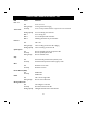
TELEPHONE OPERATIONS SETUP LIST OF SYSTEM DEFAULTS The default telephone setup is as follows: Function Tone/Pulse Mode Default Tone Headset Disable Extension Number 11 Ringer On - 4 lines Line Connection On - 4 lines Speaker Volume 12th level Handset Volume Minimum level Headset Volume Middle level Ringer Volume Middle level Speed Dial Empty Area Code Empty Calendar Jan 01 Fr 12:00 am Caller ID Log Empty You may clear all programmed data and all the parameters will revert to the ab
NOTE: The programmable speed dial keys double in function as Direct, Station to Station (DSS) keys. The upper most left key is extension (Station) 11, the next key to the right is extension 12, etc. When using the features intercom (ICM) and page, extensions may be dialed by pressing these keys even after each key has also been programmed as a speed dial number. SETTING THE CLOCK AND CALENDAR The time and date appear on the display screen when the phone is not in use. To set the clock and calendar: 1.
2. Press [5]. 3. Press a digit X where X is for line numbers 1-4. 4. Press [0], [1] for ON, or [0], [0] for OFF. 5. Press [MUTE]. 6. A short ring will be heard to signal successful programming. PROGRAMMING RINGER ON/OFF The ringer may be turned OFF and ON for incoming calls on a line-by-line basis. To set the ringer value for an individual phone line: 1. Press [STORE]. 2. Press [2]. 3. Press a digit X where X is for lines 1-4 4. Press [0], [1] for ON or [0], [0] for OFF. 5. Press [MUTE]. 6.
BASIC OPERATIONS MAKING AN OUTGOING CALL Using the Handset 1. Lift the handset. The first available line is automatically selected. 2. Dial desired number. The display will show the digits as they are dialing. 3. At the end of the call, return the handset to the base. Using the Speakerphone (hands free) 1. Press the speakerphone [SPKR] key. The first available line is automatically selected. 2. Dial the desired number. 3. At the end of the call, press [SPKR] to hang up.
USING AUTO REDIAL If the phone number dialed is busy or not answered, the phone can automatically redial the number approximately every 60 seconds up to 10 times. 1. Press an available [LINE] key [LINE1, LINE2, LINE3, or LINE4] 2. Press [REDIAL]. The [REDIAL] LED will flash and the [MUTE] key will be lit, indicating the phone is in Auto Redial mode. No further action is needed. To cancel Auto Redial: 1. Press [REDIAL] and hang up the phone. ANSWERING AN INCOMING CALL Using the Handset 1. Lift the handset.
HEADSET OPERATION A headset has been included for your convenience to provide optional hands-free operation. 1. To use the headset, you must ENABLE it. The default value is DISABLE. 2. Once headset operation mode is enabled, your telephone unit won’t detect the status of the hook switch (under the handset). 3. On-hook and off-hook functions are then activated by the [SPKR] button until you disable this function.
MAKING AN OUTGOING CALL USING THE HEADSET 1. The [SPKR] LED will flash to indicate the phone is in headset mode. 2. Press the [SPKR] key. An available line is automatically selected. 3. Dial the desired number, using standard dial pad, speed dial or redial keys. ANSWERING AN INCOMING CALL 1. Press the flashing [LINE] key (Lines 1-4) to pick up the ringing outside line. 2. Another option is to press the [SPKR] key to pick up the ringing outside line automatically.
INTERCOM The Intercom function allows extension-to-extension conversations (phones must be connected to [LINE 1]). That means you can speak with another party without having to dial seven digits (using an outside line). As you direct an intercom call to an extension that extension will ring and display a flashing ICM LED. DIRECT STATION SELECT (DSS) KEYS The phone system is preprogrammed so that with the touch of a button, you can dial any of the extensions 11–22.
7. If the called number is set on Do Not Disturb [DND], you will hear an ICM busy tone. The called party will not hear anything, but that extension’s ICM LED will flash. ANSWERING AN INTERCOM CALL Answering an Intercom Call with the Handset 1. Lift the handset. You will know you are receiving an intercom call because the [ICM] LED flashes, the display will show “ICM” on the screen and you will hear the distinct ICM ring (a double ring). 2.
PAGING Paging differs from Intercom calling in that the party called does not have to answer the phone in order to hear your message. This permits the caller to broadcast message to one or all other phone extensions. PAGING A SPECIFIC EXTENSION (INDIVIDUAL PAGE) 1. Press the [PAGE] key. (You may use the handset, headset or speakerphone to place the call.) The [ICM] LED will be lit. 2. Dial the desired phone extension or press one of the DSS keys. Your display will show the extension which you are paging.
CALLER ID This feature requires Caller ID subscription from the local telephone company. If you have multiple phone lines, you need to subscribe to Caller ID service on each line (defined as each different phone number) in order for Caller ID to display on those lines. CALLER IDENTIFICATION DISPLAYS Caller ID Displayed when the Phone is Idle 1. The phone rings, signaling an outside call. 2. The display shows the caller’s name and number and line that the call is coming in on. 3.
Setting the Caller ID Local Area Code 1. Press [STORE] key. 2. Press [7], [1]. 3. Key in 1 to 5 digits as the area code. 4. Press [MUTE]. 5. A short ring will be heard to signal successful programming. NOTE: Remember to delete any local phone numbers that have been stored with their area code prior to the area code programming. This way they can be automatically restored as a phone number without the area code the next time you receive a call from that number. Erasing the Caller ID Area Code 1.
Erasing Caller ID Records In order to delete a specific Caller ID record in the log: 1. Using the [<] or [>] key, find the particular record you would like to delete.. 2. Press the [ERASE] key. The LCD display will indicate that the record has been deleted. 3. You may erase all caller information records simultaneously by pressing [ERASE] from the summary Call ID display. Returning a Call on the Caller’s List When reviewing Caller ID entries, you may decide to return a particular call immediately.
TELEPHONE FEATURES AND OPERATIONS PAUSE You may use this feature to create a dialing pause between digits during a call. Typically, the PAUSE function is most useful for programming dialing delays in long number sequences of certain Speed Dial numbers such as voicemail codes, international phone numbers, and personal banking authorizations. Each time you press the [REDIAL] key, you add a three second delay to the dialing sequence (you may do this more than once to create a longer delay.
1. To activate the DND function, press the [DND] key. 2. To cancel DND, press the [DND] key again. USING THE CALL TIMER You can time the length of a phone call. The timer automatically begins ticking as soon as the handset/ headset/speakerphone are connected to an outside line. You must reset the timer if you don’t want the timer to begin ticking until the other party answers the phone. To reset the timer, you must: 1. Press [SHIFT] + [TIMER] to stop the timer. 2.
SPEED DIALING There are a total of 24 memory locations located in two groups, in which you can store your Speed Dial numbers. Each memory location can store up to 24 digits, including PAUSE, FLASH, PULSE and TONE. Storing Numbers into the First Speed Dial Group 1. Press the [STORE] key. 2. Enter the number to be stored including “1” if the call is long distance. 3. Press the corresponding Speed Dial key. A short ring will be heard to signal successful programming.
Erasing First Group Speed Dial Numbers 1. Press the [STORE] key. 2. Press [*]. 3. Press the SPEED DIAL key you which to erase. A ring tone will be heard signaling successful deletion of the Speed Dial number. Erasing Second Group Speed Dial Numbers 1. Press the [STORE] key. 2. Press [*]. 3. Press [SHIFT]. 4. Press the SPEED DIAL key you wish to erase. A ring tone will be heard signaling successful deletion of the Speed Dial number.
There may be times when you wish to manually turn off the flashing voice mail indicator. To do this: 1. The phone is in idle mode press [ERASE] key 2. The display will read “Del MW indicator”. 3. Press [ERASE] key to confirm. 4. A short ring will be heard to signal successful programming. NOTE: The MSG/CALLS LED may still be lit indicating new calls. Once the calls have been viewed (Caller ID Log) the light will go out entirely. ACCESSING YOUR VOICE MAIL 1. Dial the number for your voice messaging service.
TECHNICAL SPECIFICATIONS Flash Rate for Lights On Steady Solid light. Flashing Slowly 1 sec on, 1 sec off, repeatedly. Flashing Rapidly: 0.125 sec on, 0.125 sec off, repeatedly. Blink 1: 1.875 sec on, 0.125 sec off, repeatedly. Blink 2: 0.875 sec on, 0.125 sec off, repeatedly. Blink 3: 0.125 sec on, 0.875 sec off, repeatedly. Sound Rate of Intercom Buzzer Ring: 0.25 sec on. Double ring: 0.25 sec on, 0.25 sec off, 0.25 sec on, 0.25 sec off. ICM ring: 0.25 sec on, 0.25 sec off, 0.
CARE AND MAINTENANCE Your IBM-412/CID telephone has been designed to give years of trouble free service. It is a sensitive electromechanical instrument. To assure its longevity, please read the following maintenance instructions. 1. Keep the IBM-412/CID away from heat as high temperatures can shorten the life of the electrical components and distort or melt its plastic parts. 2. The IBM-412/CID should be kept free of dust and moisture. If it gets wet, wipe it dry immediately.
TROUBLESHOOTING Intercom, line status, auto-answer, privacy or auto-line selection are inoperable. • Check if Lines 1 and 2 are cross wired in the wall jack. • If used, see if you may have installed your 2-line adapter incorrectly. • Be sure all extensions in the system are connected to [LINE 1]. • Check the assigned extension codes, making sure they are unique. • Be sure the length of cable between stations does not exceed 300 feet.
Handset doesn’t appear to be working. • Check to see if your phone is in headset mode. If the [SPKR] key is flashing, you are in headset mode and need to deactivate this in order to turn on the handset. • Make sure the handset cord is connected at both ends. Intercom service doesn’t appear to work. • Check to make sure the phone lines for all extensions are set up consistently, meaning that all phones are properly wired for [LINE 1], 2, 3 and 4. Review “Connecting Your Telephone Lines” section.
AASTRA TELECOM — LIMITED WARRANTY Statement of limited warranty: Aastra Telecom Inc. warrants that for a period of one year from the date of purchase that this product 1) is free from defects in materials and workmanship and 2) conforms to its specifications. If this product does not function as warranted during the warranty period, Aastra Telecom Inc., at its option, will either replace this product with one that is functionally equivalent or will refund your purchase price.
WALL MOUNTING TEMPLATE PLACE THIS TEMPLATE ON THE WALL. THE LOCATION OF THE SCREWS IS INDICATED BY THE CENTERS OF THE CROSSED LINES.
11A99 43