IBM 4685-K03 POS Keyboard Installation, Operation, and Maintenance Guide P/N 29R0777
IBM is a trademark of the IBM Corporation in the United States or other countries. First Edition (May 2006) This manual is revised in accordance with product improvements or for other reasons. © Copyright International Business Machines Corporation 2006. All rights reserved.
Introduction This manual provides an overview, installation instructions, operating guidelines, instructions on how to replace the keys, and general maintenance information for the IBM™ 4685-K03 POS Keyboard. In this manual, the IBM 4685-K03 POS Keyboard may be referred to as the 4685-K03 or as the keyboard. The IBM 4800 POS terminal may be referred to as the POS terminal or as the terminal.
_________________________________________________________________ Notices _________________________________________________________________________________________ Electronic Emission Notices Japanese Voluntary Control Council for Interference (VCCI) Statement This product is Class A Information Technology Equipment and conforms to the standards set by the Voluntary Control Council for Interference by Technology Equipment (VCCI).
Handling Removed Cards Logic cards removed from a product should be placed in ESD protective containers. No other object should be allowed inside the ESD container with the logic card. Attach tags or reports that must accompany the card to the outside of the container. _________________________________________________________________ Related Publications For related information, please see the following websites: z http://www.ibm.com/jp/store/ z http://www.pc.ibm.
vi IBM 4685-K03 Installation, Operation and Maintenance Guide
Safety Information for Users Safety Instructions vii
Safety Information for service personnel Before you begin to install or service this product, please read the following safety information. Note: In these notices, the term, qualified service personnel, refers to a person with the skills to perform a PC upgrade.
Safety Instructions ix
_________________________________________________________________________________________ Safety Information for Korea x IBM 4685-K03 Installation, Operation and Maintenance Guide
Safety Instructions xi
Contents INTRODUCTION..................................................................................................................................................................... III WHO SHOULD USE THIS GUIDE........................................................................................................................................ III END OF LIFE DISPOSAL.......................................................................................................................................
DAILY CARE............................................................................................................................................................................ 12 CHAPTER 4 “REPLACING THE KEYS”............................................................................................................................. 15 REPLACING A SINGLE KEY................................................................................................................................................
Chapter 1 “An overview of the IBM 4685-K03 POS Keyboard” This chapter provides an overview of the IBM 4685-K03 POS Keyboard, explains how to confirm the identification of the product, gives the names of the parts, and describes the key layout at time of shipment. _________________________________________________________________________________________ An overview The IBM 4685-K03 POS keyboard is equipped with an MSR (Magnetic Stripe Reader).
_________________________________________________________________________________________ Confirmation of product Confirm the following parts are included.
_________________________________________________________________________________________ Parts name 4685-K03 model Mode switch System keys S1 S2 MSR 2 IBM 4685-K03 Installation, Operation and Maintenance Guide
_________________________________________________________________________________________ Key layout at shipment time 4685-K03 model Chapter 1 Outline for IBM 4685-K02 POS Keyboard 3
Chapter 2 “Installing the keyboard” This section explains how the Keyboard is installed on the IBM 4800 POS terminal. _________________________________________________________________________________________ Installation for IBM 4800 POS terminal This section explains how Keyboard is installed on the IBM 4800 POS terminal (also referred to as the system device). 1. Connect the keyboard cable 5 to the keyboard. Notes: a.
With the video display Without the video display 3. 6 Put the keyboard in place on the system device.
4. Connect the keyboard cable to the system device. (See the instruction manual that comes with the IBM 4800 POS terminal for more information about how to connect the keyboard cable to the system device.
Chapter 3 “Operating the keyboard” This chapter explains the operating procedures and the functions of the parts. _________________________________________________________________________________________ System keys The system keys are used to input system functions, which are run under the control of a program. Regarding the usage of these keys, please refer to the operating manual in your store or call your system representatives. The layout of the system keys is shown in the following chart.
Notes: 1. Use your fingers, not a tool, when adjusting the speaker volume. 2. The volume adjustment control is on the bottom of the keyboard. The speaker volume should be set when installing the keyboard on the system device.
_________________________________________________________________________________________ Mode switch The key-controlled mode switch is used to select the operating mode of the 4685-K03. The mode switch has four positions that are selected with mode keys. Both the operator key and manager key will control the switch. A mode key cannot be removed unless the current mode is set to “Inactive” or “Operator”. 4-position mode key Operator (“OP”) key: This key can select two modes: “Inactive,” “Operator.
________________________________________________________________________________________ How to swipe a card through the MSR This section explains how to swipe a card through the MSR (magnetic stripe reader). 1. Hold the card horizontally with the stripe at the bottom and facing away from the keyboard. 2. Position the card at the farther end of the MSR and swipe the card through the slot toward the operator with a smooth, steady motion.
Chapter 3 Operating the keyboard 13
Chapter 4 “Replacing the keys” You are free to change the layout of the keys except for the ten keys of the numeric keypad. For example, frequently used keys can be made into larger double keys by replacing two single keys with one double key. This chapter explains how to replace single keys, double keys, quadruple keys, and unused key covers on the keyboard. Before replacing keys, put the POS terminal into standby mode (system lamp off) by pushing the standby button.
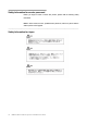
3. Remove the black rubber ring. Rubber ring (Black) Attaching 1. Insert the black rubber ring. Insert the cup with the Rubber ring (Black) larger opening facing up. 2. Insert the key. Be careful not to bend the spring attached to the key. Key Spring 3. Attach the key.
_________________________________________________________________________________________ Replacing a double key Removal 1. Pull off the key cap with the removal tool. (See “Replacing a single key” on page 17.) 2. Pinch the key lightly with the removal tool, and Removal tool pull it out. Be careful not to bend the springs attached to the key. Key Spring 3. Remove the two rubber rings (black and brown). Rubber rings (Brown) (Black) 4.
Attaching 1. Insert the key guide into the hole that will not use a scan code. 2. Key guide Insert the brown rubber ring around the (Brown) hole where the key guide was inserted. Insert the black rubber ring at the location without the key guide. (Black) 3. Insert the key. Be careful not to bend the springs attached to the key. Key Spring 4. 18 Attach the key.
_________________________________________________________________________________________ Replacing a quadruple key Removal The removal procedure for quadruple keys is the same as for single or double keys. 1. Pull off the key cap with the removal tool. 2. Pull off the key with the removal tool. Be careful not to bend the springs attached to the key. 3. Remove the two black rubber rings. 4. Remove the two key guides with the opposite end of the removal tool.
3. Make sure the scan code leg is aligned with the proper hole, and insert the quadruple key. Be Key careful not to bend the springs attached to the key. Spring 4. Label the key cap. Attach the key cap on top of the key. _________________________________________________________________________________________ Replacing an unused key cover Removal 1. Pinch the unused key cover with the removal tool. Pull up on the unused key cover.
Chapter 5 “Maintenance of the keyboard” This section is provided for the maintainer of the IBM 4685-K03 POS keyboard. Be sure to read “Safety instructions” on page ⅴ and “Safety inspection guide” on page ⅶ before working on this product. _________________________________________________________________________________________ If problems occur This section explains how to handle problems encountered when using the IBM 4685-K03 keyboard.
Symptom Causes and actions The MSR is unable to read Cause 1 There MSR reading head needs to be cleaned. Action 1 Clean the MSR reading head by using the MSR cleaning card in the cards. hardware service kit (P/N: 48G9045). Cause 2 The MSR or the control card has a problem. Action 2 Check if the MSR is functional using the diagnostic program or the self-diagnostic test. See “Diagnostic test” on page 20 for more information.
Mode switch test (Self-diagnostic test) Switching the mode key switch to a new position should cause the speaker to beep once. MSR Test (Self-diagnostic test) If a magnetic card is scanned through the MSR, the speaker should beep twice. Key Input Test (Self-diagnostic test) Pressing any key should cause the speaker to beep twice. Note: This test does not work if the position of the mode key is pointing at “Inactive”. The mode key switch must be in one of the other positions.
_________________________________________________________________________________________ Removing and replacing parts Replacing the rear cover 1. Remove the 7 screws labeled 1. Remove the rear cover 2. Reverse the procedure to reassemble.
Replacing the control card 1. 2. 3. 4. Remove the rear cover. See “Replacing the rear cover” on page 22. Remove the screw labeled 2 which holds the ground cable 1 and the cover. Open the cover. Disconnect the cables of two sheets for the membrane 4 and the other connectors from the control card 3. Remove the four screws labeled 5. Remove the control card 3. Reverse the procedure to reassemble.
2 1 26 IBM 4685-K03 Installation, Operation and Maintenance Guide
Replacing the mode key 1. 2. 3. Detach the guide label. Remove the two screws labeled 1 Remove the rear cover. See “Replacing the rear cover” on page 22. Disconnect the cable leading to the control card. Remove the mode key 2. Reverse the procedure to reassemble. Use the new guide label attached to the FRU. 1 2 Replacing the speaker 1. 2. 3. Remove the rear cover. See “Replacing the rear cover” on page 22. Open the two latches labeled 1 that hold the speaker in place.
_________________________________________________________________________________________ Bill of material Assembly: Keyboard 3 6 4 3 5 2 1 28 IBM 4685-K03 Installation, Operation and Maintenance Guide
ASM-Index Part Number 29R0782 Unit Description POS Keyboard Unit, 4685-K03 1 29R0784 1 z Bottom Cover Asm 2 29R0786 1 z Control Card Asm 3 29R0783 1 z Top Cover, Asm 4 29R0785 1 z Magnetic Stripe Reader (MSR) with MSR Cable 5 29R0787 1 z 4 position Mode Key Switch Asm with Cable 6 29R0788 1 z Speaker Asm 07N1027 z Ten Key for 4685-K02/K03 07N1032 z Key 1x1 (5 sets) 07N1033 z Key 1x2 (5 sets) 48G9045 z Hardware Service Kit — MSR Cleaning Card — MSR Test Card 29R0789 z Dum
30 IBM 4685-K03 Installation, Operation and Maintenance Guide
_________________________________________________________________________________________ Appendix A. Accessory unit You should order accessory units from an IBM sales representative or your dealer.
32 IBM 4685-K03 Installation, Operation and Maintenance Guide
Appendix B. Product specifications Dimensions 4685-K03 Width 365 mm Depth 170 mm Height 50 mm Weight 1.
Printed in Japan IBM Japan, Ltd.