Hardware Maintenance Manual IBM PC Server/Enterprise Racks IBM
Hardware Maintenance Manual IBM PC Server/Enterprise Racks IBM
Note: Before using this information and the product it supports, be sure to read the general information under “Notices” on page 195.
About this supplement This supplement contains diagnostic and service information for the IBM PC Server Rack Enclosure and the IBM Rack enclosures: IBM PC Server Rack Enclosure models: • Type 9306 19-inch and 24-inch Models: — 4QS, 4QX, 9QS — 9QX, 9TS, 9TX • IBM Rack enclosure models: — Type 9306 Models 200, 900 — Type 9308 Models 42P, 42X, 42S, 42E, 4SA, 4SB (NetBAY42 Enterprise) • IBM NetBAY3 enclosure • IBM NetBAY3E enclosure This supplement should be used with the related service information in
For information about iv See publication PC Servers IBM PC Servers Hardware Maintenance Manual (S30H-2501) PS/2 Computers IBM Personal System/2 Hardware Maintenance Manual (S52G-9971) PS/ValuePoint Computers IBM PS/ValuePoint Hardware Maintenance Service and Reference (S61G-1423) Laptop, Notebook, Portable, and ThinkPad Computers (L40, CL57, N45, N51, P70/P75, ThinkPad 300, 350, 500, 510, 710T, Expansion Unit, Dock I, Dock II) IBM Mobile Systems Hardware Maintenance Manual Volume 1 (S82G-1501) Th
Contents About this supplement . . . . . . . . . . . . . . . iii Related publications . . . . . . . . . . . . . . . . . . . . . . . . . . . . . . iii IBM PC Server/Enterprise rack enclosures 1 General checkout . . . . . . . . . . . . . . . . . . . . . . . . . . . . . . . . . 1 Power checkout . . . . . . . . . . . . . . . . . . . . . . . . . . . . . . . . . . 2 Powering off the rack . . . . . . . . . . . . . . . . . . . . . . . . . . . . . 3 Type 9306 Models 4QS, 4QX, 9QS, 9QX, 9TS, 9TX . . . . . . . . . .
Line cords . . . . . . . . . . . . . . . . . . . . . . . . . . . . . . . . . . Power cables . . . . . . . . . . . . . . . . . . . . . . . . . . . . . . . . NetBAY server dual-cord Power Distribution Unit introduction . . . . . . . . . . . . . . . . . . . . . . . . . . . . . . . . . . . Tool requirements . . . . . . . . . . . . . . . . . . . . . . . . . . . Installation overview. . . . . . . . . . . . . . . . . . . . . . . . . Installing devices vertically . . . . . . . . . . . . . . . . . . .
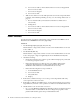
IBM PC Server/Enterprise rack enclosures General checkout. . . . . . . . . . . . . . . . . . . . . . . . . . . . . 1 Power checkout . . . . . . . . . . . . . . . . . . . . . . . . . . . . . . 2 Powering off the rack. . . . . . . . . . . . . . . . . . . . . . . . . 3 General checkout Use the following procedure for diagnosing keyboard, mouse, and video problems for the IBM PC Server Rack Enclosure and the IBM Rack enclosures (Type 9306 and Type 9308). For power problems, see “Power checkout” on page 2.
b. Server selector cable (connects between the server selector keypad and the server selector unit). c. Server selector keypad. d. Server selector unit. • YES: Power-off the server rack and replace the server rack components in the following order until the problem goes away. See “Powering off the rack” on page 3. a. Device extender cable (connects between the device and the server selector unit) b. Failing device c.
• Yes: Power-off the server rack and replace the server rack components in the following order until the problem goes away. See “Powering off the rack” on page 3. a. Power distribution unit fuse. b. Power distribution unit. Powering off the rack Before performing service on the rack, follow this procedure to prevent personal injury and to avoid damaging the rack and the installed servers. To power-off the IBM PC Server Rack: 1. Shut down and power-off all installed servers. 2.
4 Hardware Maintenance Manual: IBM PC Server/Enterprise Racks
Type 9306 Models 4QS, 4QX, 9QS, 9QX, 9TS, 9TX Features. . . . . . . . . . . . . . . . . . . . . . . . . . . . . . . . . . . . . 5 IBM PC Server expansion rack models . . . . . . . . . . 5 Locations. . . . . . . . . . . . . . . . . . . . . . . . . . . . . . . . . . . . 5 Server selector console . . . . . . . . . . . . . . . . . . . . . . . . 6 Server selector unit . . . . . . . . . . . . . . . . . . . . . . . . . . . 6 Connections . . . . . . . . . . . . . . . . . . . . . . . . . . . . . . . . .
Server selector console To remove the Server Selector Console: 1. Power-off the rack. 2. Use an 1/8-inch allen wrench to remove screws. 3. Disconnect the server selector cable from the back of the server selector console. 4. Remove the server selector console from the cabinet. Monitor Bezel Server Selector Keypad Server Selector Console Server Selector Electronics Server Selector Cable Server selector unit The server selector unit is located in the upper rear of the rack cabinet.
Server Selector Unit Server Selector Cable Connections AC Power Input Server Monitor Connections Server Rack Monitor Connection M O N O V G A 1 V G A 2 V G A 3 V G A 4 V G A 5 V G A 6 Server Selector Unit On-Off Switch V G A 7 V G A 8 KM B OKMKMKMKMKMK MKMKM OU 1 1 2 2 3 3 4 4 5 5 6 6 7 7 8 8 Server Rack Mouse Connection Server Rack Keyboard Connection Server Keyboard and Mouse Connections Power distribution unit Note: For information and installation instructions for the IBM NetBAY Rack P
Note: These screws are held in place by nuts and washers. Hold the nut while you are unscrewing the screw to prevent the nut and washer from falling into the bottom of the cabinet. 4. Remove the power distribution unit from the cabinet. AC Power Input AC Fuse Circuit Breaker 115V AC Power-On Indicator AC Power Output Voltage Selection Switch 230V AC Power-On Indicator Cooling fan To remove the cooling fan: 1. Power-off the rack. 2. Open the rear door of the rack cabinet. 3.
Ground Wire Power Plug Sliding trays Models 4QS and 4QX come with either single latch slide rails or dual latch slide rails. Single latch slide rails have a front latch release on the right rail only. Dual latch slide rails have a front latch release on both rails. The slide rail FRU number for the 24-inch rack replaces the single latch slide rail with the dual latch slide rail. Note: If a server is installed on a tray being removed, first remove the server.
Dual latch rail tray To remove a sliding tray with dual latch rails: 1. Power-off the rack. 2. Open the rear door of the rack cabinet and remove the pin 1 that secures the sliding tray to the cable management arm. 3. Loosen the thumbscrews 2 on the sliding tray and fully extend the sliding tray. 4. Push in on the spring of the right rear locking tab 3 and push the sliding tray approximately two inches into the cabinet. 5. Release both left and right forward locking tabs 4.
Note: You will need to adjust the position of the sliding rail in order to line up the access holes over the locations of the screws. Keyboard tray To remove the keyboard tray: 1. Power-off the rack. 2. Disconnect the keyboard and mouse cables from the keyboard and mouse extension cables. 3. Remove the keyboard and mouse from the keyboard tray. 4. Pull the keyboard tray straight out of the rack cabinet.
Parts listing (Type 9306 – 19-inch) Models 9QS, 9TS and 9QX, 9TX This parts listing is for Models 9QS, 9TS and 9QX, 9TX 4 8 7 5 6 9 10 3 1 28 11 13 2 29 12 30 14 27 24 23 20 22 25 21 19 18 15 26 17 16 12 Hardware Maintenance Manual: IBM PC Server/Enterprise Racks
Index 1 19-Inch Rack Enclosure (Type 9306) FRU Adapter Plate Options: PS/2 Server 85/95 76H3733 Model 300 76H3734 Model 500, 700 76H3734 2 Monitor Stand 07H0061 3 Server Selector Cable 07H0036 4 Blank Bezel (9QX, 9TX Expansion units only) 76H0379 5 Monitor Bezel with button label 76H0378 6 Server Selector Keypad 07H0097 7 Monitor Housing (19-inch) 76H0377 8 Server Selector Unit Electronics See “Safety inspection guide” on page 192.
Index FRU 1-phase NEMA L5-30P line cord (100-127 Vac) for NetBAY Front-end PDU 00N7722 1-phase NEMA L6-30P line cord (200-240 Vac) for NetBAY Front-end PDU 00N7723 1-phase IEC 309-2P+Gnd line cord (200-240 Vac) for NetBAY Front-end PDU 00N7724 NetBAY Server Dual-cord Power Distribution Unit 09N9669 Hardware Kit for NetBAY Power Distribution Units 09N9671 Power Distribution Unit 07H0424 19 250 V Slow Blow Fuse 0303549 20 Keyboard Slides, (one pair) 07H0038 21 Leveling Foot (Qty.
Rack Enclosure Kits (Type 9306) Bolt-Together Kit (19-Inch to 24-Inch, 24-Inch to 19-Inch) • 19-Inch Attachment Bracket (2 each) • Screw 1/4-20 x 1/2 Button Head Socket Cap Allen (8 each) • Screw 1/4-20 x 1-1/4 Socket Cap (4 each) • Flanged Nut 1/4-20 (12 each) • 24-Inch Attachment Bracket (4 each) Cable Kit Shelf Server (12- foot cables) • Monitor Cable • Keyboard Cable • Mouse Cable • Internal Power Cable Cable Kit Top Shelf Server (7-foot cables) • Monitor Cable • Keyboard Cable •
Rack Enclosure Kits (Type 9306) Miscellaneous Parts Kit • Rack Nut/Holder 10-32 (8 each) • Keeper Nut 8-32 Zinc (8 each) • Keeper Nut 10-32 (6 each) • Screw 6-32 x 5/16 (2 each) • Screw 6-32 x 1/4 Button Head Socket Cap Allen (8 each) • Screw 10-32 x 3/8 Button Head Socket Cap (8 each) • Screw 6-32 x 3/8 Button Head Socket Cap (2 each) • Screw 1/4-20 x 1/2 Button Head Socket Cap (2 each) • Screw 8-32 x 1/4 Button Head Socket Cap Allen (4 each) • Screw 10-32 x 1/4 Button Head Socket Cap (2
Parts listing (Type 9306 – 24-inch) Models 4QS, 4QX This parts listing is for Models 4QS and 4QX.
Index 1 FRU Adapter Plate Options: PS/2 Server 85/95 76H3733 Model 300 76H3734 Model 500, 700 76H3735 2 Monitor Stand 07H0061 3 Server Selector Cable 07H0036 4 Blank Bezel (4QX Only) 07H0066 5 Monitor Housing (24-Inch) 07H0065 6 Server Selector Keypad 07H0097 7 Rack Frame 8 Spacer (see Spacer Kit, right side at end of this FRU list) 07H0059 9 Server Selector Unit Electronics See "Safety Notice (Multi-lingual Translations) See “Safety notice (multi-lingual translations)” on page
Index 24-Inch Rack Enclosure (Type 9306) FRU 20 Leveling Feet (Qty.
20 Hardware Maintenance Manual: IBM PC Server/Enterprise Racks
Type 9306 Model 200 Features. . . . . . . . . . . . . . . . . . . . . . . . . . . . . . . . . . . . 21 Locations. . . . . . . . . . . . . . . . . . . . . . . . . . . . . . . . . . . 21 Side panel . . . . . . . . . . . . . . . . . . . . . . . . . . . . . . . . . . 21 Selector switch locations . . . . . . . . . . . . . . . . . . . . . 22 Power Distribution Unit. . . . . . . . . . . . . . . . . . . . . . 26 Blank bezel . . . . . . . . . . . . . . . . . . . . . . . . . . . . . . . . . 27 Fixed shelf . . . . . .
Selector switch locations Three Two K Three K Three K Two Three K Two K One t Rese Aux. K M K M K M M M M Figure 1. Selector switch in monitor compartment 22 Hardware Maintenance Manual: IBM PC Server/Enterprise Racks M M Important Information Note: For information about the IBM NetBAY Console Switch, see “IBM NetBAY console switch” on page 129.
1 0 K K K K K K K K Aux. Reset One M Two M Three M Two M Three M Three M Two M Three M t rtan Impo ation rm Info FRONT REAR Figure 2. Selector switch between side panels Figure 3.
Selector switch cable connections Computer 3 Monitor Aux. Keyboard Two One Reset K M K Three M K Computer 3 Keyboard Mouse K M M Computer 3 Mouse Power Co Connecto Important Information Monitor Power Switch Tiered switch configuration Monitor Keyboard Mouse Connectors System 1 to 8 Aux. Two One Reset K M K Three M K M K System 1-1 to 1-8 Aux.
Selector switch environment Monitor Keyboard Mouse Selector Switch Server 1 Console Cable Set Server 2 Server 3 Server 4 Figure 4. Single selector switch Monitor Keyboard Mouse Primary Selector Switch Console Cable Set Server 1 Server 2 Server 3 Secondary Selector Switch Server 4 Server 5 Figure 5.
Power Distribution Unit Note: For information and installation instructions for the IBM NetBAY Rack Power Distribution Units, see “NetBAY Power Distribution Units” on page 141. REAR FRONT Figure 6. Power Distribution vertical installation Figure 7.
Note: There are two types of Power distribution units available: • High voltage • Low voltage Blank bezel Fixed shelf Type 9306 Model 200 27
Keyboard tray To remove the tray from the side rails, pull up on the left rail tab and push down on the right rail tab.
Installing a flat panel monitor rack mount kit You can store a T54 or T55 Flat Panel Monitor in a keyboard tray with the flat panel monitor rack mount kit. This kit requires an additional 2U of space above an installed keyboard tray in your rack cabinet. See the documentation that comes with the flat panel monitor rack mount kit for detailed installation instructions.
1. Unplug the flat panel monitor and disconnect the power cord from the flat panel monitor power supply. 2. Carefully use a flat-blade screwdriver to pry the bottom of the cable cover c1d up and remove it. Save the cable cover for later reinstallation. Figure 9. Removing the cable cover, hinge cover, and stand cover 3. Squeeze the sides of the hinge cover c2d and remove it. Note: Even though this hinge cover is not used with the Flat Panel Monitor Rack Mount Kit, do not discard it.
Figure 11. Removing the existing monitor stand from the monitor 7. Lift off the hinge and monitor stand assembly. Store this assembly in a safe place for possible future use. Installing the new monitor stand Refer to “Removing the existing flat panel monitor stand” on page 29 for instructions on how to remove the existing stand from the flat panel monitor.
Figure 13. Installing the hinges on the flat panel monitor Note: Be sure to slide each hinge into place on the back of the monitor and align the holes in the hinges with holes on the monitor. 3. Lower the flat panel monitor onto the new monitor stand, making sure that you align the holes in the stand with holes in the hinges; then, secure the flat panel monitor to the monitor stand with the four screws that you removed earlier. Figure 14.
Figure 15. Installing the flat panel monitor in the keyboard tray Note: Clean the installation area on the keyboard tray with a suitable cleaning agent, such as alcohol, before installing the rubber bumpers on the front of the keyboard tray. 5. Open the flat panel monitorc1d to its full upright position and align the grooves in the stand with the mounting studs c2d in the keyboard tray. When the monitor stand is sitting inside the keyboard tray, slide it towards the back until it stops.
Figure 16. Storing the power supply and routing cables 8. Connect the power supply to the monitor and route the cable under the tab near the top of the monitor stand c1d; then, secure the power cable with the cable clamp you removed from the original stand and coil excess cable inside the monitor stand. 9. Connect the monitor signal cable to the monitor and route it under the tab in the bottom of the monitor stand c2d and out the back of the stand through the hole provided. 10.
Figure 18. Routing the keyboard cable 14. Route the space-saver keyboard cable through the hole in the front of the base and out the opening in the back where you removed the small cover; then, place the keyboard (with its adjustable feet fully down) inside the keyboard tray. Note: You must open the flat panel monitor to its full upright position so that you can install the keyboard and route its cable. 15.
Switch configuration can be performed to: • Assign unique names to servers. • Display servers by their assigned port names and port numbers. Switching among servers To switch among servers: • Press the Print Screen key. • Type the port number of the server to be switched. • Press Enter. Note: One depression of the Print Screen key starts the switching process. To print a screen, depress the Print Screen key twice.
Port Name CentralOfc 2 + Downtown 6 Foreign 7 + Magic 1 + Sales-A 5 + Sales-B 4 Sales-C 3 + 8 F1 Help • F2 Advanced Using the Up Arrow (h and Down Arrow (d), select the server you want to switch to, or press the numeric key that corresponds to the server’s port number and then press Enter.
Scanning the servers To place the selector switch in scan mode: • Press the Print Screen key • Press the F2 key to display the Advanced Menu screen. • Using the Up Arrow (h) and Down Arrow (d) keys, move the highlighting to Scan and press Enter. The selector switch enters the scan mode and the display returns to the status flag. To cancel the operation, press Esc any time before you press Enter. • To cancel the scan mode, press any key or move the mouse.
— Enabled or disabled — Sample rate — Resolution — Mouse type • Press Esc to remove the Version menu. Saving Hardware Configuration Whenever servers are added to or removed from the configuration, or whenever there is a change in the mouse or monitor, save the hardware configuration setting by: 1. Press the Print Screen key. 2. Press the F2 key to display the Advanced Menu screen. 3. Using the Up Arrow (h) and Down Arrow (d) keys, move the highlighting to Snapshot and press the Enter key.
Scan Pattern Setup Port/Sec Name 6/20 Downtown 5/20 Sales-A 4/10 Sales-B 1/10 Match F2 for defaults If Name order was selected, the Port and Name columns will be reversed. 4. Using the keyboard keys, select the port number of the first server to be included in the scan. Note that the server name, if any is assigned, appears in the far right column on the menu. 5. Press the Tab key or Right Arrow ( g) key to move the highlighting to the Sec column.
Port Naming 4. Port Name 1 MAGIC 2 CENTRALOFC 3 SALES-C 4 SALES-B 5 SALES-A 6 DOWNTOWN 7 8 FOREIGN Move the highlighting to the Port entry for which the server name is to be entered or changed. Type in the name of the server using up to 12 alphanumeric characters. Note: Legal characters are A-Z, 0-9, and the dash character. Lowercase letters are converted to uppercase. Press the Backspace key to delete an incorrect entry. 5.
OSCAR Attributes Resolution 640 Height 16 Horizontal 12 Vertical 7 Background 1 Highlight 4 Text 7 Delay Time Order 0 Port • Highlight the settings you want to change and use the + or - keys to change the values. As you select different values, the effect of the changes is reflected immediately on the display. • When all changes are completed, press the Enter key to save the changes to nonvolatile RAM.
Setting Effect on Menu or Window Appearance Resolution Affects the size of the menu and windows as they appear on the display. Choose from values of 320, 480, and 640. The lower the value, the larger the size. Height Affects the size of the text in the menu and windows. The larger the value, the larger the text. Horizontal/Vertical Determines the position of the menu or window on the screen. Background Determines the menu or window background color.
4. Highlight the setting to be changed and use the + and - keys to adjust the values.
Device Settings 4. Port Monitor 1 SVGA 2 SVGA 3 8515 4 SVGA 5 Default 6 Default 7 Default 8 8port To assign a monitor type, highlight the port you want and use the + or - keys to select the value that corresponds to the particular monitor. To assign a secondary selector switch to a port, highlight the port and use the + or - keys to obtain the appropriate port value. 5. Press the Enter key to save the settings. Press Esc at any time before pressing Enter to cancel the operation. 6.
Making connections under power Additional servers, can be connected to the selector switch while the selector switch is running. Failed devices such as a keyboard or mouse can be connected to a running selector switch. Note: When new devices are connected, the selector switch recognizes it and configures it to the settings of the currently selected server.
Parts Listing (Type 9306 Model 200) 9 1 10 2 3 4 8 5 6 7 Type 9306 Model 200 47
Index 48 Rack Enclosure (Type 9306 Model 200) FRU 1 Top Cover including cover standoffs and screws 28L0548 2 Rear EIA Rail (1) includes mounting hardware 28L0547 3 Rack Frame 28L0550 Caster (1) 12J4466 Leveler (1) 76H4960 4 Rear Door Assembly including latch and lock 28L0545 5 Side Panel Assembly with Latches and Lock 28L0549 Side Panel Latches 12J4468 Side Panel Lock with Keys 76H4965 6 Caster Extension Plinth (1) 12J4482 7 Stabilizer 12J4485 8 Front Door Assembly includin
Rack Enclosure (Type 9306 Model 200) Options FRU Video, Mouse, Keyboard Cable (12 feet) 06P6007 Video, Mouse, Keyboard Power Cable (25 feet) 12J4484 Mouse Extension Cable 07H0069 Keyboard Extension Cable 07H0067 Concentrator (4 port) with Hardware 28L0543 Concentrator (8 port) with Hardware 76H4948 1x4 switch 06P6003 2x8 switch 06P6004 NetBAY Rack Power Distribution Unit 09N9668 NetBAY Front-end Power Distribution Unit 09N9670 3-phase NEMA L21-30P line cord (200-250 Vac) for NetBAY Fro
50 Hardware Maintenance Manual: IBM PC Server/Enterprise Racks
Type 9306 Model 900/910 Features. . . . . . . . . . . . . . . . . . . . . . . . . . . . . . . . . . . . 51 Locations. . . . . . . . . . . . . . . . . . . . . . . . . . . . . . . . . . . 51 Side Panel . . . . . . . . . . . . . . . . . . . . . . . . . . . . . . . . . . 51 Perforated Doors (model 910) . . . . . . . . . . . . . . . . . 52 Installing the new door on a model 900 rack cabinet 53 Selector switch locations . . . . . . . . . . . . . . . . . . . . . 54 Power Distribution Unit. . . . . . . . . . . . .
Locked Unlocked Perforated Doors (model 910) The Type 9306 Model 910 Rack comes with front and rear perforated doors that provide enhanced cooling and airflow for components you install in your rack cabinet. The 9306 Model 910 Rack also comes with side panels already installed.
Refer to installation instructions in this document if you have a 9306 Model 900 Rack and are installing a new perforated front door. Note: The illustrations in this documentation might be slightly different from your hardware. Installing the new door on a model 900 rack cabinet Use the following steps to remove your existing front door and install the new perforated door: 1.
® Note: Insert the screw through the bracket and into the lower of the two holes in the new center location. 5. Remove the other hinge bracket c3d and store it with the old door that you removed earlier. 6. While supporting the new door, use three of the hinge pins that you removed from the old door to attach the new door to your rack cabinet. Store the fourth hinge pin with the old door and hinge bracket. 7. Reinstall the left side panel that you removed earlier.
1 0 K K K K K K K K Aux. Reset One M Two M Three M Two M Three M Three M Two M Three M t rtan Impo ation rm Info FRONT REAR Figure 20. Selector switch between side panels Figure 21.
Selector switch cable connections: Computer 3 Monitor One Reset Aux. Keyboard K M Three Two K K M M Computer 3 Keyboard Mouse K M Computer 3 Mouse Power Co Connecto Important Information Monitor Power Switch Tiered switch configuration: Monitor Keyboard Mouse Connectors System 1 to 8 Aux. Two One Reset K M K Three M K M K System 1-1 to 1-8 Aux.
Selector switch environment: Monitor Keyboard Mouse Selector Switch Server 1 Console Cable Set Server 2 Server 3 Server 4 Figure 22. Single selector switch Monitor Keyboard Mouse Primary Selector Switch Console Cable Set Server 1 Server 2 Server 3 Secondary Selector Switch Server 4 Server 5 Figure 23.
REAR FRONT Figure 24. Power Distribution installation Figure 25.
Blank bezel Fixed shelf Type 9306 Model 900/910 59
Keyboard tray To remove the tray from the side rails, pull up on the left rail tab and push down on the right rail tab.
Installing a flat panel monitor rack mount kit You can store a T54 or T55 Flat Panel Monitor in a keyboard tray with the flat panel monitor rack mount kit. This kit requires an additional 2U of space above an installed keyboard tray in your rack cabinet. See the documentation that comes with the flat panel monitor rack mount kit for detailed installation instructions.
1. Unplug the flat panel monitor and disconnect the power cord from the flat panel monitor power supply. 2. Carefully use a flat-blade screwdriver to pry the bottom of the cable cover c1d up and remove it. Save the cable cover for later reinstallation. Figure 27. Removing the cable cover, hinge cover, and stand cover 3. Squeeze the sides of the hinge cover c2d and remove it. Note: Even though this hinge cover is not used with the Flat Panel Monitor Rack Mount Kit, do not discard it.
Figure 29. Removing the existing monitor stand from the monitor 7. Lift off the hinge and monitor stand assembly. Store this assembly in a safe place for possible future use. Installing the new monitor stand Refer to “Removing the existing flat panel monitor stand” on page 61 for instructions on how to remove the existing stand from the flat panel monitor.
Figure 31. Installing the hinges on the flat panel monitor Note: Be sure to slide each hinge into place on the back of the monitor and align the holes in the hinges with holes on the monitor. 3. Lower the flat panel monitor onto the new monitor stand, making sure that you align the holes in the stand with holes in the hinges; then, secure the flat panel monitor to the monitor stand with the four screws that you removed earlier. Figure 32.
Figure 33. Installing the flat panel monitor in the keyboard tray Note: Clean the installation area on the keyboard tray with a suitable cleaning agent, such as alcohol, before installing the rubber bumpers on the front of the keyboard tray. 5. Open the flat panel monitorc1d to its full upright position and align the grooves in the stand with the mounting studs c2d in the keyboard tray. When the monitor stand is sitting inside the keyboard tray, slide it towards the back until it stops.
Figure 34. Storing the power supply and routing cables 8. Connect the power supply to the monitor and route the cable under the tab near the top of the monitor stand c1d; then, secure the power cable with the cable clamp you removed from the original stand and coil excess cable inside the monitor stand. 9. Connect the monitor signal cable to the monitor and route it under the tab in the bottom of the monitor stand c2d and out the back of the stand through the hole provided. 10.
Figure 36. Routing the keyboard cable 14. Route the space-saver keyboard cable through the hole in the front of the base and out the opening in the back where you removed the small cover; then, place the keyboard (with its adjustable feet fully down) inside the keyboard tray. Note: You must open the flat panel monitor to its full upright position so that you can install the keyboard and route its cable. 15.
Switch configuration can be performed to: • Assign unique names to servers. • Display servers by their assigned port names and port numbers. Switching among servers To switch among servers: • Press the Print Screen key. • Type the port number of the server to be switched. • Press Enter. Note: One depression of the Print Screen key starts the switching process. To print a screen, depress the Print Screen key twice.
Port Name CentralOfc 2 + Downtown 6 Foreign 7 + Magic 1 + Sales-A 5 + Sales-B 4 Sales-C 3 + 8 F1 Help • F2 Advanced Using the Up Arrow (h and Down Arrow (d), select the server you want to switch to, or press the numeric key that corresponds to the server’s port number and then press Enter.
• Press the F2 key to display the Advanced Menu screen. • Using the Up Arrow (h) and Down Arrow (d) keys, move the highlighting to Scan and press Enter. The selector switch enters the scan mode and the display returns to the status flag. To cancel the operation, press Esc any time before you press Enter. • To cancel the scan mode, press any key or move the mouse. The scan stops at the currently connected server.
Saving hardware configuration: Whenever servers are added to or removed from the configuration, or whenever there is a change in the mouse or monitor, save the hardware configuration setting by: 1. Press the Print Screen key. 2. Press the F2 key to display the Advanced Menu screen. 3. Using the Up Arrow (h) and Down Arrow (d) keys, move the highlighting to Snapshot and press the Enter key. The hardware settings are saved to memory.
length of time you want this server to be connected to the monitor and keyboard, before switching to the next server in the scan. 6. Press the Down Arrow (d) key to move the highlighting to the next port in the Port column and repeat step 5. To delete unwanted ports from the scan list in the Scan Pattern Setup window, place the highlighting on the top-most port to be removed and press the Delete key (not the Del key on the numeric keypad). 7.
Changing menu attributes: The menus displayed on the monitor can be altered in visual appearance to suit the particular use of the system. You can: • Position the menu in a convenient location on the display. • List servers by port or by name, whichever is desired, in the appropriate menus. • Adjust character height. • Change colors. • Display the selection menu for a certain period. To change the menu attributes, do the following: • Press the Print Screen key.
4. F10 5. Y 6. Enter Available menu attributes: Setting Effect on Menu or Window Appearance Resolution Affects the size of the menu and windows as they appear on the display. Choose from values of 320, 480, and 640. The lower the value, the larger the size. Height Affects the size of the text in the menu and windows. The larger the value, the larger the text. Horizontal/Vertical Determines the position of the menu or window on the screen.
Flag Attributes 4. Enabled Names on Row 14 Column 1 Color 2 Text 0 Mode Transparent Highlight the setting to be changed and use the + and - keys to adjust the values.
Device Settings 4. Port Monitor 1 SVGA 2 SVGA 3 8515 4 SVGA 5 Default 6 Default 7 Default 8 8port To assign a monitor type, highlight the port you want and use the + or - keys to select the value that corresponds to the particular monitor. To assign a secondary selector switch to a port, highlight the port and use the + or - keys to obtain the appropriate 8port value. 5. Press the Enter key to save the settings. Press Esc at any time before pressing Enter to cancel the operation. 6.
Parts listing (Type 9306 Model 900/910) 9 10 11 1 2 3 4 5 8 7 6 Type 9306 Model 900/910 77
Index Rack Enclosure (Type 9306 Model 900/910) FRU 1 Top Cover including cover standoffs and screws 12J4481 2 Rear EIA Rail (1) includes mounting hardware 76H4956 3 Rack Frame 76H4959 Caster (1) 12J4466 Leveler (1) 76H4960 4 Rear Door Assembly including latch and lock 12J4478 5 Side Panel Assembly (option for model 900, standard for model 910) including latches and lock 76H4949 6 Stabilizer Bar (1) 12J4467 7 Caster Extension Plinth (1) 12J4482 8 Front Stabilizer (1) 12J4485 9
Rack Enclosure (Type 9306 Model 900/910) Options FRU Filler Panels: 1U, 3U, and 5U - with Hardware 12J4473 Keyboard Tray 76H4958 Keyboard Tray II 28L0562 Keyboard Tray II filler block 28L0567 Keyboard Slides (set) with Hardware 76H4961 Fixed Shelf with Hardware 76H4963 Rack to Rack Mounting Kit - Includes: Horizontal Trim (1); Vertical Trim (2); M6x16 Screws (12); M6 Cage Nuts (4); M6 Whiz nuts (10); Brackets, Rack Mounting (4) 12J4476 C13 - C14 Power Cable 07H0075 C19 - C14 Power Cable 7
80 Hardware Maintenance Manual: IBM PC Server/Enterprise Racks
NetBAY 42 Enterprise Rack (Type 9308 Models 42P, 42X, 4SA, 4SB, 42S, 42E) Features. . . . . . . . . . . . . . . . . . . . . . . . . . . . . . . . . . . . 81 Locations. . . . . . . . . . . . . . . . . . . . . . . . . . . . . . . . . . . 85 Removing and installing panels . . . . . . . . . . . . . . . 85 Doors . . . . . . . . . . . . . . . . . . . . . . . . . . . . . . . . . . . . . . 87 Removing and installing the top 6U portion of the rack . . . . . . . . . . . . . . . . . . . . . . . . . . . . . . . . . . .
Primary Rack (Model 42P) 82 Hardware Maintenance Manual: IBM PC Server/Enterprise Racks
Extension Rack (Model 42X) NetBAY 42 Enterprise Rack (Type 9308 Models 42P, 42X, 4SA, 4SB, 42S, 42E) 83
Primary Rack (42S) 84 Hardware Maintenance Manual: IBM PC Server/Enterprise Racks
Expansion Rack (42E) Locations The following sections contain information on specific equipment locations. Removing and installing panels The primary rack cabinet comes with side panels installed. Remove the side panels from a primary rack cabinet, or the outermost rack cabinets in a suite, before you install or remove optional devices. Note: You do not need to remove the top 6U side panels unless you are removing the top 6U portion of the rack cabinet.
Release latches Side panel locking bar Tabs Figure 37. Removing the rack side panels 1. From the inside of the rear of the rack cabinet, slide the side panel locking bar toward the unlocked position. 2. Push down the release latches and tilt the side panel slightly toward you; then, lift the side panel away from the tabs on the bottom of the rack cabinet. 3. Repeat this procedure to remove both side panels. Reverse this procedure to install the rack side panels.
Figure 38. Removing the top 6U side panels from the rack cabinet 1. On the top of the rack cabinet, loosen the four screws that hold each side panel in place. 2. Tilt the side panel slightly toward you; then, remove it from the rack cabinet. 3. Repeat this procedure to remove both side panels. Reverse this procedure to install the top 6U side panels on the rack cabinet.
Front and rear doors – Models 42P, 42X, 4SA, 4SB To remove a door: 1. Unlock the door and open it fully. 2. Grasp the door c1d firmly with both hands and lift it upwards until it is fully off of the hinges c2d. Notes: 88 1. Reverse this procedure to reinstall front and rear doors. 2. The top hinge pin is longer than the bottom; engage it first when you reinstall doors.
Rear door – Models 42S, 42E Use the following procedure to remove a rear door from the rack cabinet: Rear door Bottom hinge pin Figure 39. Removing a rear door from the rack cabinet 1. Unlock and open the rear door. 2. Grasp the door firmly with both hands and lift it upward and away from the hinges; then, set the door aside. Reverse this procedure to install the rear door on the rack cabinet. Attention: The bottom hinge pin on the rear door is longer than the top hinge pin.
Front door – Models 42S, 42E Use the following procedure to remove a front door from the rack cabinet: Front door Hinge pin latch Hinge pin Figure 40.
1. Unlock and open the front door. 2. While supporting the door, lift the bottom hinge-pin latch and move it clockwise to unlock the bottom hinge pin; then, unlock the top hinge pin. 3. Pull the door away from the rack cabinet; then, set the door aside. Reverse this procedure to install the front door on the rack cabinet. Attention: When you install the front door, ensure that you align the hinge pins with the hinges on the rack cabinet before you lock the hinge pins into place.
2. Remove the 16 screws (eight per side) that hold the top 6U portion of the rack cabinet in place. 3. Relocate your rack cabinet; then, install the top 6U portion of the rack cabinet using all 16 of the screws that you removed. 4. Remove both support bars from the rack cabinet. Installing the stabilizer bracket To lower the leveling feet and install the stabilizer bracket: 1. Lower each of the four feet c1d just enough so that they touch the floor.
Trim piece Threaded standoff Bolt and washer Figure 42. Attaching two adjacent rack cabinets to each other to form a suite 1. Remove both side panels (see “Removing and installing the side panels” on page 85) from the side of a primary rack cabinet that is adjacent to an expansion rack in a suite. 2. Remove the front and rear doors (see “Doors” on page 87) from all rack cabinets. 3.
5. Snap the trim pieces into place between the adjacent rack cabinets. Install one trim piece in the front and one in the rear. 6. Repeat step 3 through step 5 for all other adjacent rack cabinets in the suite. 7. On the outside of the outermost expansion rack cabinets in the suite, install the side panels that you removed in step 1. 8. Install the front and rear doors on all rack cabinets. Installing L-channel support rails to rack mounting brackets 1.
Note: Use clip nuts if your rack has holes. If your rack has square holes, you can use the rack-insertion tool or a flat-blade screwdriver to install cage nuts. 2. On the rail marked R, loosen the four screws c2d. 3. Hold the rail against the outside of the right rack-mounting flange, and loosely insert the two front M6 screws c1d. 4. Extend the rail outside of the rear rack-mounting flange; then, install and tighten two rear M6 screws c3d. 5.
6. Loosely insert one M5 screw c1d into each rail. Statement 4 ≥18 kg (37 lbs) ≥32 kg (70.5 lbs) ≥55 kg (121.2 lbs) CAUTION: Use safe practices when lifting. 7. 96 Slide the expansion unit into the rack, and insert the M6 screws c1d. Do not overtighten the M6 c1d screws.
8. Tighten the rear screws c2d. Installing a server A small server can occupy from 1U to 5U of rack mounting space. A large server can occupy 8U or more of rack mounting space. Most servers also come with cablemanagement arms so that you can neatly route any cables that you attach to your server. See the documentation that comes with your server for detailed installation instructions.
Installing a large server Use the following general procedure to install a large server in your rack cabinet: Cable-management arm Rear of rail Server rail screws Front of rail Server handles Figure 43. Installing a large server 1. See the server documentation for detailed installation and configuration information. 2. Use the template and rack mounting instructions that come with your server to determine where to install clip nuts. 3.
Installing a small server Use the following general procedure to install a small server in your rack cabinet: Cable-management arm Rail adjustment Server screws Rear of rail Front of rail Figure 44. Installing a small server 1. See the server documentation for detailed installation and configuration information. 2. Use the template and rack mounting instructions that come with your server to determine where to install clip nuts. 3.
Fixed shelf Note: A fixed shelf can support a device or option weighing up to 45kg (100 lbs). To install a fixed shelf: 100 1. Determine the location for the fixed shelf within the rack. 2. Secure the threaded mounting brackets c1d to the rear of the shelf; then, secure the brackets to the rack with two screws and clip nuts per bracket. 3. Secure the front of the shelf c2d with two screws and clip nuts.
Keyboard tray To install a keyboard tray: 1. Secure the slide rails to the front c1d and rear c2d of the rack, adjusting them as needed. 2. Slide the keyboard tray onto the rails and store the keyboard c3d in the area provided.
Monitor shelf To install a monitor shelf: 102 1. Secure the rear monitor shelf bracket in the rear of the rack c1d with two screws per side. 2. Place the monitor shelf inside of the rack, resting on the rear bracket; then, secure it to the front of the rack c2d with three screws and clip nuts per side.
Installing a flat panel monitor rack mount kit You can store a T54 or T55 Flat Panel Monitor in a keyboard tray with the flat panel monitor rack mount kit. This kit requires an additional 2U of space above an installed keyboard tray in your rack cabinet. See the documentation that comes with the flat panel monitor rack mount kit for detailed installation instructions.
1. Unplug the flat panel monitor and disconnect the power cord from the flat panel monitor power supply. 2. Carefully use a flat-blade screwdriver to pry the bottom of the cable cover c1d up and remove it. Save the cable cover for later reinstallation. Figure 46. Removing the cable cover, hinge cover, and stand cover 3. Squeeze the sides of the hinge cover c2d and remove it. Note: Even though this hinge cover is not used with the Flat Panel Monitor Rack Mount Kit, do not discard it.
Figure 48. Removing the existing monitor stand from the monitor 7. Lift off the hinge and monitor stand assembly. Store this assembly in a safe place for possible future use. Installing the new monitor stand Refer to “Removing the existing flat panel monitor stand” on page 103 for instructions on how to remove the existing stand from the flat panel monitor.
Figure 50. Installing the hinges on the flat panel monitor Note: Be sure to slide each hinge into place on the back of the monitor and align the holes in the hinges with holes on the monitor. 3. Lower the flat panel monitor onto the new monitor stand, making sure that you align the holes in the stand with holes in the hinges; then, secure the flat panel monitor to the monitor stand with the four screws that you removed earlier. Figure 51.
Figure 52. Installing the flat panel monitor in the keyboard tray Note: Clean the installation area on the keyboard tray with a suitable cleaning agent, such as alcohol, before installing the rubber bumpers on the front of the keyboard tray. 5. Open the flat panel monitorc1d to its full upright position and align the grooves in the stand with the mounting studs c2d in the keyboard tray. When the monitor stand is sitting inside the keyboard tray, slide it towards the back until it stops.
Figure 53. Storing the power supply and routing cables 8. Connect the power supply to the monitor and route the cable under the tab near the top of the monitor stand c1d; then, secure the power cable with the cable clamp you removed from the original stand and coil excess cable inside the monitor stand. 9. Connect the monitor signal cable to the monitor and route it under the tab in the bottom of the monitor stand c2d and out the back of the stand through the hole provided. 10.
Figure 55. Routing the keyboard cable 14. Route the space-saver keyboard cable through the hole in the front of the base and out the opening in the back where you removed the small cover; then, place the keyboard (with its adjustable feet fully down) inside the keyboard tray. Note: You must open the flat panel monitor to its full upright position so that you can install the keyboard and route its cable. 15.
To install a blank filler panel: 110 1. Determine the size (1U, 3U, or 5U) panel you need. 2. Secure the blank filler panel in place with four screws and clip nuts.
Parts listing (Type 9308 Model 42P, 42X) 1 7 6 Index 5 2 3 4 Rack Enclosure (Type 9308 Model 42P, 42X, 4SA, 4SB, 42S, 42E) FRU 1 Top Cover Assembly including cover standoffs and screws (All models) 05N4896 2 Cabinet Frame (All models) 05N4895 3 Front Door w/Lock (Models 42P, 42X) 05N4897 Rear Door w/Lock (Models 42P, 42X) 05N4899 Front Door w/Lock (Models 42S, 42E) 09N9694 Rear Door w/Lock (Models 42S, 42E) 06P6047 Front Door (Models 4SA, 4SB) 05N4899 Rear Door (Models 4SA, 4SB)
Index Rack Enclosure (Type 9308 Model 42P, 42X, 4SA, 4SB, 42S, 42E) Leveling foot wrench (All models) Rack Enclosure (Type 9308 Model 42P, 42X, 4SA, 4SB, 42S, 42E) Options 112 FRU 05N4927 FRU Monitor Housing 76H4947 Side Panel Latch 12J4468 Filler Panels: 1U, 3U, and 5U - with Hardware 12J4473 Keyboard Tray 76H4958 Keyboard Tray II 28L0562 Keyboard Tray II filler block 28L0567 Keyboard Slides (set) with Hardware 76H4961 Fixed Shelf with Hardware 76H4963 C13 - C14 Power Cable 07H0075
Rack Enclosure (Type 9308 Model 42P, 42X, 4SA, 4SB, 42S, 42E) Options Flat Panel Adapter Display Housing – Includes: Power Supply Cover (1); Base Housing (1); Cable Access Cover (1); Bottom Stand FRU 00N8694 NetBAY 42 Enterprise Rack (Type 9308 Models 42P, 42X, 4SA, 4SB, 42S, 42E) 113
114 Hardware Maintenance Manual: IBM PC Server/Enterprise Racks
NetBAY3 enclosure Features. . . . . . . . . . . . . . . . . . . . . . . . . . . . . . . . . . . Locations. . . . . . . . . . . . . . . . . . . . . . . . . . . . . . . . . . Casters. . . . . . . . . . . . . . . . . . . . . . . . . . . . . . . . . . . . Foot pads . . . . . . . . . . . . . . . . . . . . . . . . . . . . . . . . . Front cover . . . . . . . . . . . . . . . . . . . . . . . . . . . . . . . . 115 115 116 116 117 Rear panel . . . . . . . . . . . . . . . . . . . . . . . . . . . . . . . . .
Casters • Two fixed casters c1d at the front of the NetBAY3 enclosure. • Two swivel casters c2d at the rear of the NetBAY3 enclosure.
Front cover Rear panel Note: Make sure empty NetBAY3 enclosures (no devices installed) have the rear cover securely attached.
Device side rails Stacking NetBAY3 enclosures Note: Make sure NetBAY3 enclosures in a stack are securely fastened together.
Note: The maximum server weight is 77 kg (170 lb.).
120 Hardware Maintenance Manual: IBM PC Server/Enterprise Racks
Parts Listing (NetBAY3) 4 1 3 2 Index NetBAY3 Enclosure (NetBAY3) FRU 1 3-U Enclosure Frame 03K8797 2 Front Bezel Assembly with Lock and Keys 03K8798 3 Foot Pads Qty. 4 03K8800 4 Casters Fixed, Front, Qty. 2 12J3279 4 Casters Swivel, Rear, Qty.
122 Hardware Maintenance Manual: IBM PC Server/Enterprise Racks
NetBAY3E enclosure Features. . . . . . . . . . . . . . . . . . . . . . . . . . . . . . . . . . . 123 Locations. . . . . . . . . . . . . . . . . . . . . . . . . . . . . . . . . . 123 Casters. . . . . . . . . . . . . . . . . . . . . . . . . . . . . . . . . . . . 124 Front cover . . . . . . . . . . . . . . . . . . . . . . . . . . . . . . . . 124 Rear panel . . . . . . . . . . . . . . . . . . . . . . . . . . . . . . . . Device side rails . . . . . . . . . . . . . . . . . . . . . . . . . . .
Casters • Two fixed casters 1 at the front of the NetBAY3E enclosure. • Two swivel casters 2 at the rear of the NetBAY3E enclosure.
Rear panel Note: Make sure empty NetBAY3E enclosures (no devices installed) have the rear cover securely attached.
Device side rails Stacking NetBAY3E enclosures Notes: 1. Make sure NetBAY3E enclosures in a stack are securely fastened together. 2. When stacking an enclosure on top of another, you must attach them together before you install any device in the upper enclosure. Important: 126 • Always lock the casters with the caster stabilizer bar before removing or installing any devices in or on the enclosure. • Always use the caster stabilizer when multiple NetBAY3E enclosures are stacked under a server.
Notes: 1. The maximum server weight is 77 kg (170 lb.). 2. Always install a server on the top enclosure in a stack. Carefully lift the server by its handles and align its mounting holes 1 with the NetBAY3E enclosure mounting studs 2. Parts listing (NetBAY3E) 4 1 3 2 Index NetBAY3E Enclosure (NetBAY3E) FRU 1 3-U Enclosure Frame 28L0571 2 Front Bezel Assembly with Lock and Keys 03K8798 3 Casters Fixed, Front, Qty. 2 12J3279 3 Casters Swivel, Rear, Qty.
128 Hardware Maintenance Manual: IBM PC Server/Enterprise Racks
IBM NetBAY console switch Installing a console switch vertically in a rack. . 134 Installing a console switch horizontally in a rack . . 137 Parts listing (NetBAY Console Switch) . . . . . . . . 139 Features. . . . . . . . . . . . . . . . . . . . . . . . . . . . . . . . . . . 130 Tool requirements . . . . . . . . . . . . . . . . . . . . . . . . . . 131 Specifications . . . . . . . . . . . . . . . . . . . . . . . . . . . . . . 132 Installation overview . . . . . . . . . . . . . . . . . . . . . . .
1x4 Console Switch 2x8 Console Switch Two vertical mounting brackets Two vertical mounting brackets Miscellaneous hardware kit (for attaching brackets and installing the console switch in a rack cabinet) Two horizontal mounting brackets, marked ’L’ and ’R’ (Left and Right) One 1.8 m (6 ft) power cord Miscellaneous hardware kit (for attaching brackets and installing the console switch in a rack cabinet) One 1.5 m (4.9 ft) IEC connector power cable One 1.
Secondary monitor B Secondary keyboard Secondary mouse Server monitor ports 1-8 Primary monitor Power connector A 1 2 3 4 5 6 7 8 Primary keyboard Primary mouse Power switch Server keyboard and mouse ports 1-8 You can connect multiple console switches to each other in a tiered configuration. If you use a 1x4 Console Switch as the primary switch, you can connect up to four additional console switches and 32 servers.
• A Phillips screwdriver • A 10mm nut driver or 10mm open-end or box wrench Specifications The following table contains the product specifications for the 1x4 Console Switch and the 2x8 Console Switch: 1x4 Console Switch 2x8 Console Switch Height 4.3 cm (1.7 in.) 4.3 cm (1.7 in.) Depth 20.3 cm (8.0 in.) 20.3 cm (8.0 in.) Width 43.2 cm (17 in.) 43.2 cm (17 in.) Weight 2.38 kg (5.25 lbs) 2.59 kg (5.
Note: Removing the rack doors and side panels might make your console switch installation easier. 2. If the monitor shelf is not already installed, install the monitor shelf according to its documentation. 3. Place the console switch in the rear compartment of the monitor shelf; then, install and tighten the four M3x5 screws. Notes: a. Make sure that the rear of the console switch is facing the back of your rack cabinet. b.
A 1 2 3 4 6. Connect the monitor signal cable from your monitor to the blue monitor connector on Port A of the console switch; then, tighten the screws on the monitor signal cable. 7. Route your keyboard cable neatly toward the rear of the console switch; then, connect it to the appropriate keyboard connector on Port A of the console switch. 8. Connect one end of a console cable set to one of the numbered ports on the rear of the console switch. 9.
1. Refer to the documentation that comes with your rack cabinet for additional information. Note: Removing the rack doors and side panels might make your console switch installation easier. 2. Attach one vertical mounting bracket to each side of the console switch using two 8-32 screws per bracket. Console switch 8 7 6 5 4 3 2 1 A Vertical mounting bracket Vertical mounting bracket 3.
4. Verify that the power switch on the rear of the console switch is in the Off position before connecting any cables. 5. Route your mouse cable neatly toward the rear of the console switch; then, connect it to the appropriate mouse connector on Port A of the console switch. 6. Connect the monitor signal cable from your monitor to the blue monitor connector on Port A of the console switch; then, tighten the screws on the monitor signal cable. 7.
15. Refer to the Apex User Guide CD for configuration and operation information about your console switch. Installing a console switch horizontally in a rack Use the following procedure to install the console switch horizontally in 1U of EIA rack mounting space in your rack cabinet: 1. Refer to the documentation that comes with your rack cabinet for additional information. Notes: a. Removing the rack doors and side panels might make your console switch installation easier. b.
A 1 2 3 4 5 6 4 Important Information 7 1 0 Continue with the rest of the procedure to cable your console switch. Note: Refer to the Apex User Guide CD for additional information if you are configuring a tiered installation. 4. Verify that the power switch on the rear of the console switch is in the Off position before connecting any cables. 5. Route your mouse cable neatly toward the rear of the console switch; then, connect it to the appropriate mouse connector on Port A of the console switch.
9. Connect one end of a console cable set to one of the numbered ports on the rear of the console switch. 10. Route the console cable set toward the rear of your rack cabinet, and up or down toward your server. Use the cable straps that come with this option to secure the console cable set along the way. 11. Connect the other end of the console cable set to the appropriate monitor, mouse, and keyboard connectors on your server. 12. Repeat step 9. to step 11.
140 Hardware Maintenance Manual: IBM PC Server/Enterprise Racks
NetBAY Power Distribution Units NetBAY rack Power Distribution Unit introduction 141 Tool requirements . . . . . . . . . . . . . . . . . . . . . . . . . . 142 Installation overview . . . . . . . . . . . . . . . . . . . . . . . 142 Installing devices vertically . . . . . . . . . . . . . . . . . . 142 Installing a single device horizontally . . . . . . . . . 144 Installing two devices horizontally . . . . . . . . . . . 146 Cabling your PDUs . . . . . . . . . . . . . . . . . . . . . . . . .
4. You can install other M/PDU family devices next to your Rack PDU using mounting hardware from both devices. You can install the Rack PDU vertically in the side of your rack cabinet, or horizontally within 1U of EIA mounting space in your rack cabinet. The mounting hardware that comes with this option enables you to install one Rack PDU next to another in the same mounting space within your rack cabinet.
Note: The mounting holes on the upper and lower side braces in a rack side compartment must be between 48.6 cm (19.1 in.) and 56.9 cm (22.4 in.) apart. If your rack cabinet has movable side braces, refer to your rack documentation for information about relocating your side braces if they are not already spaced for this installation. 1. Refer to the documentation that comes with your rack cabinet for additional information.
Figure 60. Installing the vertical mounting plate and cable-management bracket 6. Install the cable-management bracket c1d beside the vertical mounting plate with four M6 screws and nuts that come with this option. Proceed to“Cabling your PDUs” on page 148 for instructions on how to cable your Rack PDU. Installing a single device horizontally Use the following procedure to mount a single Rack PDU horizontally in your rack cabinet: 1.
2. Verify that the circuit breaker switch is in the Off position before installing your Rack PDU. 3. Install the horizontal mounting bracket c3don one side of the Rack PDU c5d with M3x5 screws c4d. Note: There are two sets of mounting holes on the bracket. You can align the Rack PDU to be even with the back of the rack cabinet or recessed inside, depending on how you install the bracket. Figure 61. Installing the mounting brackets for a single device 4.
6. Install the 1U blank filler panel c1d on the front of the rack cabinet at the same U level as the Rack PDU. Use two M6 screws that come with this option. Proceed to “Cabling your PDUs” on page 148 for instructions on how to cable your Rack PDU. Installing two devices horizontally Use the following procedure to mount two Rack PDUs horizontally in your rack cabinet: 1. Refer to the documentation that comes with your rack cabinet for additional information. Notes: a.
Figure 63. Installing the mounting brackets for two devices 4. Push the two Rack PDUs together, aligning the holes on the dual-device attachment brackets; then, use four M6 screws to secure the front c1d and rear c2d of the brackets to each other. 5. Install a horizontal mounting bracket c4d on the Rack PDU on the right with two M3x5 screws c3d; then, install the other horizontal mounting bracket c7d on the Rack PDU on the left with two M3x5 screws c8d.
7 7 Figure 64. Installing two Rack PDUs and the blank filler panel 7. Install the 1U blank filler panel c1don the front of the rack cabinet at the same U level as the Rack PDU. Use two M6 screws that come with this option. Proceed to “Cabling your PDUs” on page 173 for instructions on how to cable your Rack PDU. Cabling your PDUs Cable routing differs between horizontal and vertical Rack PDU installations.
Statement 1 DANGER Electrical current from power, telephone, and communication cables is hazardous. To avoid a shock hazard: • Do not connect or disconnect any cables or perform installation, maintenance, or reconfiguration of this product during an electrical storm. • Connect all power cords to a properly wired and grounded electrical outlet. • Connect to properly wired outlets any equipment that will be attached to this product.
DANGER Overloading a branch circuit is potentially a fire hazard and a shock hazard under certain conditions. To avoid these hazards, ensure that your system electrical requirements do not exceed branch circuit protection requirements. Refer to the information that is provided with your IBM device for electrical specifiacations. Also adhere to the following statements: 1. If you are connecting to a 120-127 V ac power source, connect each power cord to a separate branch circuit. 2.
2. Reinstall the screw on the cable clamp c1d and repeat step 1 for the other device if you installed two devices. 3. Route the line cords down and toward the rack side braces; then, route the line cords along the side brace towards the back of the rack cabinet and secure them with the cable straps that come with this option. 4. Route the line cords toward a dedicated power source, such as a UPS or electrical outlet. Use the provided cable straps to secure the line cords along the way.
MAIN 456 6 7 Figure 67. Connecting and routing the line cord Reinstall the screw on the cable clamp and repeat this step for the other device, if you installed two devices. 152 2. Route the line cords left or right, toward the side of the rack cabinet; then, route the line cords along the side brace towards the back of the rack cabinet and secure them with the cable straps that come with this option. 3. Route the line cords toward a dedicated power source, such as a UPS or electrical outlet.
7 7 Figure 68.
Rack PDU specifications When connected to a dedicated power source, the Rack PDU conforms to UL950, CSA 22.0-950, EN-60950, and IEC-950 standards. The following table contains the product specifications for the Rack PDU: 154 Height 43 mm (1.7 in.) Width 192 mm (7.5 in.) Depth 221 mm (8.7 in.) Weight 1.5 kg (3.
Power cables Power cables that you use to connect a system, storage expansion unit, and other devices to the Rack PDU usually come with those devices. The following table contains a list of power cables that you can use with the Rack PDU: Length Cable rating Plug type Cable part # 2.8 m (9.2 ft) 250 V, 10 A IEC 320-C13 to IEC 320-C14 36L8886 4.
Line cords A 4.3 m (14 ft) country-specific line cord that you use to connect your Rack PDU to a properly wired, grounded, and dedicated power source comes with the Rack PDU.
• One vertical mounting plate • One vertical-mounting cable-management bracket • Miscellaneous hardware kit (for attaching brackets and installing the device in a rack cabinet) • Cable straps • Installation documentation Note: The illustrations in this documentation might be slightly different from your hardware.
Statement 1 DANGER Electrical current from power, telephone, and communication cables is hazardous. To avoid a shock hazard: • Do not connect or disconnect any cables or perform installation, maintenance, or reconfiguration of this product during an electrical storm. • Connect all power cords to a properly wired and grounded electrical outlet. • Connect to properly wired outlets any equipment that will be attached to this product.
Figure 69. Installing the Rack PDU on the vertical mounting plate 3. Install the vertical mounting plate in the side of your rack cabinet with four M6 screws and nuts that come with this option. Make sure that the three-connector side of the Rack PDU is facing up. Figure 70. Installing the vertical mounting plate 4.
1 2 3 MAIN Figure 71. Routing the fixed line cord and power cables 5. Route the line cord towards a dedicated power source. Use the provided cable straps to secure the line cord along the way. Use the openings in your rack cabinet, if you must exit the rack cabinet to connect to your power source. 6. After you connect the line cord to a properly wired and grounded dedicated power source, you can connect up to three other M/PDU family devices to the three power outlets on the Rack PDU.
Statement 1 DANGER Electrical current from power, telephone, and communication cables is hazardous. To avoid a shock hazard: • Do not connect or disconnect any cables or perform installation, maintenance, or reconfiguration of this product during an electrical storm. • Connect all power cords to a properly wired and grounded electrical outlet. • Connect to properly wired outlets any equipment that will be attached to this product.
Figure 72. Installing the Rack PDU on the vertical mounting plate 3. If you have a second M/PDU device to install, install it on the vertical mounting plate with four M3x5 screws that come with the second device. Figure 73. Installing a second Rack PDU 4. 162 Install the vertical mounting plate c2d in the side of your rack cabinet with four M6 screws and nuts that come with this option.
Figure 74. Installing the vertical mounting plate and cable-management bracket Install the cable-management bracket c1d beside the vertical mounting plate with four M6 screws and nuts that come with this option. 6. Route the fixed line cords down, towards the rack side braces; then, route the line cords along the side brace towards the back of the rack cabinet and secure them with the cable straps that come with this option. 2 3 5. MAIN 1 2 3 1 MAIN Figure 75.
Route each line cord towards a dedicated power source. Use the provided cable straps to secure the line cords along the way. Use the openings in your rack cabinet, if you must exit the rack cabinet to connect to your power source. 8. After you connect both line cords to properly wired and grounded dedicated power sources, you can connect up to three other M/PDU family devices to the three power outlets on each Rack PDU.
Height 43 mm (1.7 in.) Width 192 mm (7.5 in.) Depth 221 mm (8.7 in.) Weight 1.6 kg (3.
Length Cable rating 1 m (3.3 ft) 250 V, 16 A Plug type IEC 320-C19 to IEC 320-C20 Cable part # 00N7698 NetBAY server dual-cord Power Distribution Unit introduction The IBM NetBAY Server Dual-cord Power Distribution Unit is part of the Rack Modular Power Distribution Unit (M/PDU) family and enables you to connect one server to two dedicated, independent, and redundant power sources, such as an electrical outlet and an uninterruptable power supply (UPS).
Note: The illustrations in this documentation might be slightly different from your hardware. Tool requirements You will need the following tools to install the Rack PDU: • A Phillips screwdriver • A 10-mm nut driver or 10-mm open-end or box wrench Installation overview Use the following general steps to install your Rack PDU: 1. 2.
Figure 77. Installing the Rack PDU on the vertical mounting plate 3. If you have a second M/PDU device to install, install it on the vertical mounting plate with four M3x5 screws that come with the second device. Figure 78. Installing a second Rack PDU 4. 168 Install the vertical mounting plate c2d in the side of your rack cabinet with four M6 screws and nuts that come with this option.
Figure 79. Installing the vertical mounting plate and cable-management bracket 5. Install the cable-management bracket 1 beside the vertical mounting plate with four M6 screws and nuts that come with this option. Proceed to “Cabling your PDUs” on page 173 for instructions on how to cable your Rack PDU. Installing a single device horizontally Use the following procedure to mount a single Rack PDU horizontally in your rack cabinet: 1.
2. Install the horizontal mounting bracket c3d on one side of the Rack PDU c5d with M3x5 screws c4d. Note: There are two sets of mounting holes on the bracket. You can align the Rack PDU to be even with the back of the rack cabinet or recessed inside, depending on how you install the bracket. Figure 80. Installing the mounting brackets for a single device 3. Install the single-device attachment bracket c1d on the other side of the Rack PDU c5d with two M3x5 screws c2d.
Installing two devices horizontally Use the following procedure to mount two Rack PDUs horizontally in your rack cabinet: 1. Refer to the documentation that comes with your rack cabinet for additional information. Notes: a. Removing the rack doors and side panels might make your Rack PDU installation easier. b. Use clip nuts for rack cabinets with round holes; use cage nuts for rack cabinets with square holes. Clip nuts 2.
Figure 82. Installing the mounting brackets for two devices 3. Push the two Rack PDUs together, aligning the holes on the dual-device attachment brackets; then, use four M6 screws to secure the front c1d and rear c2d of the brackets to each other. 4. Install a horizontal mounting bracket c4d on the Rack PDU on the right with two M3x5 screws c3d; then, install the other horizontal mounting bracket c7d on the Rack PDU on the left with two M3x5 screws c8d.
Figure 83. Installing the Rack PDUs and the blank filler panel 6. Install the 1U blank filler panel c1d on the front of the rack cabinet at the same U level as the Rack PDU. Use two M6 screws that come with this option. Cabling your PDUs Cable routing differs between horizontal and vertical Rack PDU installations. Refer to “Cabling instructions for vertical-mount PDUs” on page 175 or “Cabling instructions for horizontal-mount PDUs” on page 176 as appropriate for your installation.
Statement 1 DANGER Electrical current from power, telephone, and communication cables is hazardous. To avoid a shock hazard: • Do not connect or disconnect any cables or perform installation, maintenance, or reconfiguration of this product during an electrical storm. • Connect all power cords to a properly wired and grounded electrical outlet. • Connect to properly wired outlets any equipment that will be attached to this product.
have more than one power cord. To remove all electrical current from the device, ensure that all power cords are disconnected from the power source. 2 1 Cabling instructions for vertical-mount PDUs If your Rack PDU came with more than two line cords, select either the high-voltage cords or the low-voltage cords for your installation. Use the following procedure to connect and route cables for Rack PDUs that you mounted vertically in the side of your rack cabinet: 1.
along the way. Use the openings in your rack cabinet, if you must exit the rack cabinet to connect to your power source. 6. After you connect both line cords to properly wired and grounded dedicated independent power sources, you can connect one server (having up to four line cords) to the four power outlets on the Rack PDU. Route all other power cables neatly, and use the cable-management bracket to secure the cables that you plug into the outlets on the Rack PDU. MAIN MAIN Figure 85.
Figure 86. Connecting and routing the line cords 2. Connect the other line cord to the Backup inlet on the Rack PDU. Use the line cord that you will connect to your backup power source. 3. Remove the screws on the cable clamps and route the line cords through the clamps; then, reinstall the screws on the cable clamps and repeat step 1 and step 2 for the other device, if you installed two devices. 4.
Figure 87.
Rack PDU specifications When connected to a dedicated power source, the Rack PDU conforms to UL950, CSA 22.0-950, EN-60950, and IEC-950 standards. The following table contains the product specifications for the Rack PDU: Height 43 mm (1.7 in.) Width 192 mm (7.5 in.) Depth 221 mm (8.7 in.) Weight 2.4 kg (5.
Power cables Power cables that you use to connect a server (with more than one power supply) to the Rack PDU usually come with the server. The following table contains a list of power cables that you can use with the Rack PDU: Length Cable rating Plug type Cable part # 2.8 m (9.2 ft) 250 V, 10 A IEC 320-C13 to IEC 320-C14 36L8886 4.
Line cords Two 4.3 m (14 ft) country-specific line cords that you use to connect your Rack PDU to properly wired, grounded, and dedicated power sources come with the Rack PDU. One line cord is for the Main inlet (primary power source), and the other line cord is for the Backup inlet (backup power source).
182 Hardware Maintenance Manual: IBM PC Server/Enterprise Racks
Related service information These procedures are written with the assumption that you have model-specific training on all computers, or that are familiar with the computers, functions, terminology, and service information provided in this manual. Safety information The following section contains the safety information that you need to know before servicing an IBM server or IBM supporting equipment such as the Type 9306 IBM PC Server Rack Enclosure and Type 9306 IBM Rack. 1.
1. PERIGO • O peso máximo permitido para dispositivos montados em trilhos é de 80 kg (176 lbs). Não instale dispositivos em trilhos que excedam este peso. • O centro de gravidade para uma unidade estendida não pode exceder 362 mm (14.25 in.) da frente do rack. Se um dispositivo estendido exceder esta distância, o rack configurado pode se tornar instñÚ³Ýável. 2. PERIGO • Instale sempre os servidores e dispositivos de alimentação no rack de baixo para cima.
1. DANGER 2. DANGER 3. DANGER 4.
1. DANGER 186 • Le poids maximal d'une unité montée sur glissières est de 80 kg ; n'installez pas d'unités dont le poids est supérieur. • Le centre de gravité d'une unité tirée hors de son logement ne doit pas être éloigné de plus de 362 mm de la face avant de l'armoire. Sinon, l'armoire configurée risque de ne pas être stable.
2. DANGER • Commencez toujours par installer les serveurs et les blocs d’alimentation dans la partie inférieure de l'armoire. • Installez toujours les composants les plus lourds dans la partie inférieure de l'armoire. • Installez toujours les blocs d'alimentation (UPS) dans la partie inférieure de l'armoire. • Installez toujours les stabilisateurs. • Certaines unités sont installées sur des tiroirs coulissants. N'ouvrez pas plusieurs de ces tiroirs à la fois. 3.
1. VORSICHT • Das zulässige Höchstgewicht für auf Schienen montierte Einheiten beträgt 80 kg. Keine Einheiten mit höheren Gewicht einbauen. • Der Schwerpunkt einer ausgefahrenen Einheit darf nicht mehr als 362 mm von der Frontseite des Gehäuse entfernt liegen. Liegt der Schwerpunkt weiter entfernt, kann das konfigurierte Gehäuse instabil werden. 2. VORSICHT • Server und Netzeinheiten immer von unten nach oben im Gehäuse installieren. • Die schwersten Einheiten unten installieren.
1. PERICOLO • Il peso massimo consentito per i dispositivi montati su slitte è di 80 kg. Non installare dispositivi scorrevoli che hanno un peso superiore a quello sopra citato. • Il centro di gravità di un'unità estratta non puòsuperare i 362 mm dalla superficie del rack. In caso contrario, il rack configurato potrebbe essere instabile. 2. PERICOLO • Installare sempre i serventi e gli alimentatori nel rack dal basso verso l’alto.
1. 2. 3. 4.
1. PELIGRO • El peso máximo permitido para los dispositivos montados en correderas es de 80 Kg (176 lbs). No instale dispositivos deslizantes que excedan este peso. • El centro de gravedad de una unidad extendida no puede exceder los 362 mm (14,25 pgda.) desde la parte frontal del bastidor. Si un dispositivo extendido excede esta distancia, el bastidor que lo contuviese podría ser poco estable. 2. PELIGRO • Instale siempre los servidores y dispositivos de alimentación en el bastidor de abajo a arriba.
• English • Brazilian/Portuguese • Chinese • French • German • Italian • Spanish CAUTION: The server selector unit is heavy. You will need two people to safely remove the server selector unit. A unidade seletora do servidor é pesada. Você irá precisar de duas pess oas para remover com segurança esta unidade. Le bloc sélecteur est lourd. Faites-vous aider pour le retirer en toute. Die Server Selektor Einheit ist schwer. Um sie zu transportieren, sind mindestens zwei Personen erforderlich.
Checklist: 1. Check exterior covers for damage (loose, broken, or sharp edges). 2. Power-off the computer. Disconnect the power cord. 3. Check the power cord for: a. A third-wire ground connector in good condition. Use a meter to measure third-wire ground continuity for 0.1 ohm or less between the external ground pin and frame ground. b. The power cord should be the appropriate type as specified in the parts listings. c. Insulation must not be frayed or worn. 4. Remove the cover. 5.
— Use the round ground-prong of the ac plug on ac-operated computers. Grounding requirements Electrical grounding of the PC Server Rack and computers is required for operator safety and correct system function. Proper grounding of the electrical outlet can be verified by a certified electrician. Problem determination tips Due to the variety of hardware and software combinations that can be encountered, use the following information to assist you in problem determination.
Notices References in this publication to IBM products, programs, or services do not imply that IBM intends to make these available in all countries in which IBM operates. Any reference to an IBM product, program, or service is not intended to state or imply that only that IBM product, program, or service may be used.
Send us your comments! We want to know your opinion about this manual (part number 10K2658). Your input will help us to improve our publications. Please photocopy this survey, complete it, and then fax it to IBM HMM Survey at 919-543-8167 (USA). Name: _________________________________________ Phone number: __________________________________ 1.
Trademarks The following items are trademarks of the IBM Corporation in the United States or other countries or both: IBM SystemXtra NetBAY ServeRAID ThinkPad ServerGuide ServerProven Light Path Diagnostics Predictive Failure Analysis Wake on LAN Alert on LAN xSeries TechConnect Active PCI EduQuest HelpCenter HelpClub NetBAY2 NetBAY3 NetBAY3E Netfinity OS/2 Personal System/2 PS/1 PS/2 PS/ValuePoint Skill Dynamics NetBAY42 Apex PC Solutions, OutLook, OutLook4, and OSCAR are tradema
198 Hardware Maintenance Manual: IBM PC Server/Enterprise Racks
IBM@ Part Number: File Number: 10K2658 Printed in the United States of America on recycled paper containing 10% recovered post-consumer fiber.