Hardware Maintenance Manual IBM NetVista Computer Types 6058, 6059, 6269, 6568, 6569, 6578, 6579, 6648, 6649
Hardware Maintenance Manual IBM NetVista Computer Types 6058, 6059, 6269, 6568, 6569, 6578, 6579, 6648, 6649
Note: Before using this information and the product it supports, be sure to read the general information under “Notices” on page 228.
About this manual ® This manual contains service and reference information for the IBM NetVistaTM Series computer types 6058, 6059, 6269, 6568, 6569, 6578, 6579, 6648, 6649. This manual is divided into product service sections (by machine chassis) and a related service section, as follows: v The product service sections include procedures for isolating problems to a FRU, a Symptom-to-FRU Index, additional service information and an illustrated parts catalog.
Important Safety Information Be sure to read all caution and danger statements in this book before performing any of the instructions. Prenez connaissance de toutes les consignes de type Attention et Danger avant de procéder aux opérations décrites par les instructions. Lesen Sie alle Sicherheitshinweise, bevor Sie eine Anweisung ausführen. Accertarsi di leggere tutti gli avvisi di attenzione e di pericolo prima di effettuare qualsiasi operazione.
About this manual v
vi 6649 Hardware Maintenance Manual: IBM NetVista Computer Types 6058, 6059, 6269, 6568, 6569, 6578, 6579, 6648,
Related Publications The following publications are available for IBM products. For more information, contact IBM or an IBM Authorized Dealer.
viii 6649 Hardware Maintenance Manual: IBM NetVista Computer Types 6058, 6059, 6269, 6568, 6569, 6578, 6579, 6648,
Contents About this manual . . . . Important Safety Information . . . . . . . . . . iii . iv Related Publications . . . . . vii . . . Chapter 1. IBM PC Enhanced Diagnostics error codes . . . . . . . . . . . Chapter 2. Types 6568/6569/6648/6649 . . Product description . . . . . . . . . Specifications Information (ISO/ANSI) . . Specifications - Types 6568/6569/6648/6649 . . . . . . . . General checkout . . . . . . . . . . Module test menu and hardware configuration report . . . . . . . .
Fan/speaker bracket removal . . . . Power supply removal . . . . . . Components of the riser card . . . . A40 and A40P system board layout . . . System board locations . . . . . . A40/A40P System board jumper settings A40/A40P Clear CMOS/Flash Boot Block Recovery . . . . . . . . A40/ A40P Processor Speed Settings . A40/A40P Diskette Write Access . . Symptom-to-FRU index . . . . . . . Beep symptoms . . . . . . . . . No-beep symptoms . . . . . . . POST error codes . . . . . . . .
Input/Output connectors - Type 6269 . Input/Output connectors - Types 6058/6059/6578/6579 . . . . . . Cover removal . . . . . . . . . Replacing the cover . . . . . . EMC shield (front) . . . . . . . EMC shield (system board) . . . . Installing adapters . . . . . . . Adapter slots . . . . . . . . Air duct (Types 6058/6059/6278/6279) CD-ROM drive removal. . . . . . Fan/speaker bracket removal . . . . Hard drive removal . . . . . . . Power supply removal . . . . . . A20 system board layout (Type 6269) . .
xii 6649 Hardware Maintenance Manual: IBM NetVista Computer Types 6058, 6059, 6269, 6568, 6569, 6578, 6579, 6648,
Chapter 1. IBM PC Enhanced Diagnostics error codes Refer to the following Diagnostic Error Codes when using the IBM PC Enhanced Diagnostics test. See the ″Diagnostic and test information″ section for the specific model for information about the IBM PC Enhanced Diagnostics program. In the following index, X can represent any number. Diagnostic Error Code FRU/Action 000-000-XXX BIOS Test Passed 1. No action 000-002-XXXBIOS Timeout 1. Flash the system 2.
Diagnostic Error Code FRU/Action 000-038-XXXBIOS Extension failure 1. Flash the system 2. Adapter card 3. System board 000-039-XXXBIOS DMI data error 1. Flash the system 2. System board 000-195-XXXBIOS Test aborted by user 1. Information 2. Re-start the test, if necessary 000-196-XXXBIOS test halt, error threshold exceeded 1. Press F3 to review the log file 000-197-XXXBIOS test warning 1. Make sure the component that is called out is connected and/or enabled 2.
Diagnostic Error Code FRU/Action 001-027-XXXSystem Configuration/Setup error 1. Run Setup 2. Flash the system 3. System board 001-032-XXXSystem Device Controller failure 1. System board 001-034-XXXSystem Device Buffer Allocation failure 1. Reboot the system 2. Flash the system 3. Run memory test 4. System board 001-035-XXXSystem Device Reset condition detected 1. System board 001-036-XXXSystem Register error 1. System board 001-038-XXXSystem Extension failure 1. Adapter card 2.
Diagnostic Error Code FRU/Action 001-199-XXXSystem test failed, cause unknown 1. Go to the ″Undetermined problems″ section 2. Flash the system and re-test 3. Replace component under function test 001-250-XXXSystem ECC error 1. System board 001-254-XXX 001-255-XXX 001-256-XXX 001-257-XXXSystem DMA error 1. System board 001-260-XXX 001-264-XXXSystem IRQ error 1. System board 001-268-XXXSystem IRQ1 failure 1. Device on IRQ1 2. System board 001-269-XXXSystem IRQ2 failure 1. Device on IRQ2 2.
Diagnostic Error Code FRU/Action 001-279-XXXSystem IRQ12 failure 1. Device on IRQ12 2. System board 001-280-XXXSystem IRQ13 failure 1. Device on IRQ13 2. System board 001-281-XXXSystem IRQ14(hard disk drive) failure 1. Hard disk drive cable 2. Hard disk drive 3. System board 001-282-XXXSystem IRQ15 failure 1. Device on IRQ15 2. System board 001-286-XXX 001-287-XXX 001-288-XXXSystem Timer failure 1. System board 001-292-XXXSystem CMOS RAM error 1. Run Setup and re-test 2.
Diagnostic Error Code FRU/Action 005-024-XXXVideo Addressing test failure 1. Video card, if installed 2. System board 005-025-XXXVideo Checksum Value error 1. Video card, if installed 2. System board 005-027-XXXVideo Configuration/Setup error 1. Run Setup 2. Video drivers update 3. Video card, if installed 4. System board 005-031-XXXVideo Device Cable failure 1. Video cable 2. Monitor 3. Video card, if installed 4. System board 005-032-XXXVideo Device Controller failure 1.
Diagnostic Error Code FRU/Action 005-199-XXXVideo test failed, cause unknown 1. Go to the ″Undetermined problems″ section 2. Flash the system and re-test 3. Replace component under function test 005-2XX-XXX 005-3XX-XXXVideo subsystem error 1. Video card, if installed 006-000-XXXDiskette interface Test Passed 1. No action 006-0XX-XXXDiskette interface error 1. Diskette drive Cable 2. System board 2. Diskette drive 3. System board 006-195-XXXDiskette interface Test aborted by user 1.
Diagnostic Error Code FRU/Action 011-013-XXX 011-014-XXXSerial port Control Signal/Loopback test failure 1. System board 011-015-XXXSerial port External Loopback failure 1. Wrap plug 011-027-XXXSerial port Configuration/Setup error 1. Run Setup, enable port 2. System board 2. Flash the system 3. System board 011-03X-XXX 011-04X-XXXSerial port failure 1. System board 011-195-XXXSerial port Test aborted by user 1. Information 2.
Diagnostic Error Code FRU/Action 014-013-XXX 014-014-XXXParallel port Control Signal/Loopback test failure 1. System board 014-015-XXXParallel port External Loopback failure 1. Wrap plug 014-027-XXXParallel port Configuration/Setup error 1. Run Setup, enable port 2. System board 2. Flash the system 3. System board 014-03X-XXX 014-04X-XXXParallel port failure 1. System board 014-195-XXXParallel port Test aborted by user 1. Information 2.
Diagnostic Error Code FRU/Action 015-015-XXXUSB port External Loopback failure 1. Remove USB device(s) and re-test 015-027-XXXUSB port Configuration/Setup error 1. Flash the system 2. System board 2. System board 015-032-XXXUSB port Device Controller failure 1. System board 015-034-XXXUSB port bufferallocation failure 1. Reboot the system 2. Flash the system 3. Run memory test 4. System board 015-035-XXXUSB port Reset condition detected 1. Remove USB device(s) and re-test 2.
Diagnostic Error Code FRU/Action 018-0XX-XXXPCI Card Failure 1. Riser card, if installed 2. System board 018-195-XXXPCI Card Test aborted by user 1. PCI card 2. Information 3. Re-start the test, if necessary 018-196-XXXPCI Card test halt, error threshold 1. Press F3 to review the log file exceeded 2. Re-start the test to reset the log file 018-197-XXXPCI Card test warning 1. Make sure the component that is called out is connected and/or enabled 2. Re-run test 3.
Diagnostic Error Code FRU/Action 020-197-XXXPCI test warning 1. Make sure the component that is called out is connected and/or enabled 2. Re-run test 3. Component that is called out in warning statement 4. Component under test 020-198-XXXPCI test aborted 1. If a component is called out, make sure it is connected and/or enabled 2. Flash the system and re-test 3. Go to the ″Undetermined problems″ section 020-199-XXXPCI test failed, cause unknown 1. Go to the ″Undetermined problems″ section 2.
Diagnostic Error Code FRU/Action 025-197-XXXIDE interface test warning 1. Make sure the component that is called out is connected and/or enabled 2. Re-run test 3. Component that is called out in warning statement 4. Component under test 025-198-XXXIDE interface test aborted 1. If a component is called out, make sure it is connected and/or enabled 2. Flash the system and re-test 3. Go to the ″Undetermined problems″ section 025-199-XXXIDE interface test failed, cause unknown 1.
Diagnostic Error Code FRU/Action 030-197-XXXSCSI interface test warning 1. Make sure the component that is called out is connected and/or enabled 2. Re-run test 3. Component that is called out in warning statement 4. Component under test 030-198-XXXSCSI interface test aborted 1. If a component is called out, make sure it is connected and/or enabled 2. Flash the system and re-test 3. Go to the ″Undetermined problems″ section 030-199-XXXSCSI interface test failed, cause unknown 1.
Diagnostic Error Code FRU/Action 071-00X-XXX 071-01X-XXX 071-02X-XXX Audio port error 1. Run Setup 071-03X-XXXAudio port failure 1. Speakers 2. Flash the system 3. System board 2. Microphone 3. Audio card, if installed 4. System board 071-04X-XXXAudio port failure 1. Run Setup 2. Audio card, if installed 3. System board 071-195-XXXAudio port Test aborted by user 1. Information 2. Re-start the test, if necessary 071-196-XXXAudio port test halt, error threshold exceeded 1.
Diagnostic Error Code FRU/Action 080-196-XXXGame Port interface test halt, error threshold exceeded 1. Press F3 to review the log file 080-197-XXXGame Port interface test warning 1. Make sure the component that is called out is connected and/or enabled 2. Re-start the test to reset the log file 2. Re-run test 3. Component that is called out in warning statement 4. Component under test 080-198-XXXGame Port interface test aborted 1.
Diagnostic Error Code FRU/Action 086-198-XXXMouse Port interface test aborted 1. If a component is called out, make sure it is connected and/or enabled 2. Flash the system and re-test 3. Go to the ″Undetermined problems″ section 086-199-XXXMouse Port interface test failed, cause unknown 1. Go to the ″Undetermined problems″ section 2. Flash the system and re-test 3. Replace component under function test 089-000-XXXMicroprocessor Test Passed 1. No action 089-XXX-XXXMicroprocessor failure 1.
Diagnostic Error Code FRU/Action 170-197-XXXVoltage Sensor(s) test warning 1. Make sure the component that is called out is connected and/or enabled 2. Re-run test 3. Component that is called out in warning statement 4. Component under test 170-198-XXXVoltage Sensor(s) test aborted 1. If a component is called out, make sure it is connected and/or enabled 2. Flash the system and re-test 3. Go to the ″Undetermined problems″ section 170-199-XXXVoltage Sensor(s) test failed, cause 1.
Diagnostic Error Code FRU/Action 175-199-XXXThermal Sensor(s) test failed, cause unknown 1. Go to the ″Undetermined problems″ section 2. Flash the system and re-test 3. Replace component under function test 175-250-XXX 175-251-XXXThermal Sensor(s) limit error 1. Check fans 2. Check Power supply 3. Microprocessor 4. System board 185-000-XXXAsset Security Test Passed 1. No action 185-XXX-XXXAsset Security failure 1. Flash system 2. System board 185-278-XXXAsset Security Chassis Intrusion 1.
Diagnostic Error Code FRU/Action 217-25X-XXX 217-26X-XXXHard Disk Drive (IDE) error 1. Hard Disk Drive Cable 2. Check power supply voltages 3. Hard Disk drive (IDE) 4. System board 217-28X-XXX 217-29X-XXXHard Disk Drive (SCSI) error 1. Hard Disk Drive Cable 2. Check power supply voltages 3. Hard Disk drive (SCSI) 4. SCSI adapter card 5. System board 220-000-XXXHi-Capacity Cartridge Drive Test Passed 1. No action 220-XXX-XXXHi-Capacity Cartridge Drive error 1.
Chapter 2. Types 6568/6569/6648/6649 Product description . . . . . . . . . Specifications Information (ISO/ANSI) . . Specifications - Types 6568/6569/6648/6649 . . . . . . . . General checkout . . . . . . . . . . Module test menu and hardware configuration report . . . . . . . . Keyboard . . . . . . . . . . . . Printer . . . . . . . . . . . . . Power supply . . . . . . . . . . 20-pin main power supply connection . . Display . . . . . . . . . . . . Diagnostics, test and recovery information . .
System board locations . . . . . . A40/A40P System board jumper settings A40/A40P Clear CMOS/Flash Boot Block Recovery . . . . . . . . A40/ A40P Processor Speed Settings . A40/A40P Diskette Write Access . . Symptom-to-FRU index . . . . . . . Beep symptoms . . . . . . . . . No-beep symptoms . . . . . . . POST error codes . . . . . . . . Miscellaneous error messages . . . . 22 6649 . 67 67 . . . . . . . . 67 68 68 69 70 72 72 87 Undetermined problems . . . . . . . Model tables - Country/Region/Language .
Product description The NetVista type 6568/6569/6648/6649 computers are available in 2 x 3 (two I/O adapter slots plus Ethernet, and three drive bays). v Type 6568 and 6569 are the white desktop types with the A40 and A40P system boards, respectively. v Type 6648 and 6649 are the black desktop types with the A40 and A40P system boards, respectively.
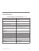
Specifications Information (ISO/ANSI) The machine type specifications information on the following pages was determined in controlled acoustical environments according to procedures specified by the American National Standards Institute (ANSI) S12.10 and ISO 7779, and are reported in accordance with ISO 9296. Actual sound pressure levels in your location might differ from the average values stated because of room reflections and other nearby noise sources.
Feature Description Electrical Input Sine-wave input (47 to 63 Hz) required Input voltage range: v Minimum: 90 V AC v Maximum: 265 V AC Input kVA (approximately):. v Minimum: 0.08 kVA v Maximum: 0.16 kVA (as shipped) Airflow Approximately 0.
General checkout This general checkout procedure is for type 6568/6569/6648/6649 computers. Attention: The drives in the computer you are servicing might have been rearranged or the drive startup sequence changed. Be extremely careful during write operations such as copying, saving or formatting. Data or programs can be overwritten if you select an incorrect drive. Diagnostic error messages appear when a test program finds a problem with a hardware option.
001 1. Power-off the computer and all external devices. 2. Check all cables and power cords. 3. Make sure the system board is seated properly. 4. 5. 6. 7. 8. Set all display controls to the middle position. Power-on all external devices. Power-on all external devices. Power-on the computer. Check for the following response: v Readable instructions or the Main Menu. DID YOU RECEIVE THE CORRECT RESPONSE? If NO, continue to 002 . If YES, proceed to 003 .
v If the computer has incorrect keyboard responses, go to “Keyboard” on page 29. v If the printer has incorrect responses, go to “Printer” on page 29. v If the display has problems such as jittering, rolling, shifting, or being out of focus, go to “Display” on page 32. Module test menu and hardware configuration report Depending on the diagnostics version level you are using, the installed devices in the computer are verified in one of two ways. 1.
Keyboard Note: If a mouse or other pointing device is attached, remove it to see if the error symptom goes away. If the symptom goes away, the mouse or pointing device is defective. 001 - Power-off the computer. Disconnect the keyboard cable from the system unit. Power-on the computer and check the keyboard cable connector on the system unit for the voltages shown. All voltages are 5%. Pin 1 2 3 4 5 6 Voltage (Vdc) +5.0 Reserved Ground +5.0 +5.
If the printer self-test runs correctly, install a wrap plug in the parallel port and run the diagnostic tests to determine which FRU failed. If the diagnostic tests (with the wrap plug installed) do not detect a failure, replace the printer cable. If that does not correct the problem, replace the system board or adapter connected to the printer cable. Power supply If the power-on indicator is not on, the power supply fan is not running, or the computer will not power-off, use the following procedures.
20-pin main power supply connection See “A40 and A40P system board layout” on page 67 for connector locations. Attention These voltages must be checked with the power supply cables connected to the system board. Pin Signal Function 1 3.3 V +3.3 V dc 2 3.3 V +3.3 V dc 3 COM Ground 4 5V +5 V dc 5 COM Ground 6 5V +5 V dc 7 COM Ground 8 POK Power Good 9 5VSB Standby Voltage 10 12 V +12 V dc 11 3.3 V +3.
Display If the screen is rolling, replace the display assembly. If that does not correct the problem, replace the video adapter (if installed) or replace the system board. If the screen is not rolling, use the following procedure to run the display self-test. 1. Power-off the computer and display. 2. Disconnect the display signal cable. 3. Power-on the display. 4. Turn the brightness and contrast controls clockwise to their maximum setting. 5. Check for the following conditions.
Diagnostics, test and recovery information The following tools are available to help identify and resolve hardware-related problems. v Power-On Self-Test (POST) – POST Beep Codes – Error Code Format v IBM PC Enhanced Diagnostics v Recovery utility – Full recovery – Partial recovery v Repair utility Power-On Self-Test (POST) Each time you power-on the system, it performs a series of tests that check the operation of the system and some options. This series of tests is called the Power-On Self-Test, or POST.
One beep and the appearance of text on the display indicates successful completion of the POST. More than one beep indicates that the POST detects an error. Error code format This section provides an explanation of the encoded non-SCSI and SCSI POST error codes. Error messages are displayed on the screen as three, four, five, eight, twelve, or thirteen digits. An X in an error message can be any number or letter. The shorter POST errors are highlighted in the Symptom-to-FRU Index.
This utility reformats the hard drive and restores all original files. v Partial recovery This utility reformats the hard drive and restores the Windows operating system and all device drivers v Repair This is the emergency repair utility, and should not be used to install Windows components. v System utilities 1. Run diagnostics This selection accesses the IBM PC Enhanced Diagnostics. 2. System info 3.
Navigating through the diagnostics programs Use the cursor movement keys to navigate within the menus. v The Enter key is used to select a menu item. v The Esc key is used to back up to the previous menu. v For online help select F1. Running diagnostics tests There are four ways to run the diagnostic tests. 1. Using the cursor movement keys, highlight Run Normal Test or Run Quick Test from the Diagnostics Menu and then press Enter.
Follow the steps below to locate the IBM PC Enhanced Memory Diagnostics test options. 1. Select the DIAGNOSTICS option on the toolbar and press Enter. 2. Highlight either the Memory Test-Full or Memory Test-Quick option and press Enter. 3. Memory Test-Full The full memory test will take about 80 seconds per MB of memory and will detect marginal, intermittent, and solid (stuck) memory failures. 4.
Represents the type of error encountered. v DeviceID: Contains the component’s unit-ID which corresponds to either a fixed disk drive, removable media drive, serial or parallel port, processor, specific SIMM or DIMM, or a device on the PCI bus. v Date: Contains the date on which the diagnostic test was run. The date is retrieved from CMOS and displayed using the YYYYMMDD format. v ChkDigits: Contains a 2-digit check-digit value to ensure the following: – Diagnostics were run on the specified date.
2. Select Fixed Disk Optimized Test. 3. Select one of the tests: v Hard Disk Test - Full performs a complete test of the hard disk drive. v Hard Disk Test - Quick performs a subset of the full hard disk tests. v Start SMART Hard Disk Test initiates an IDE extended offline self-test. v SMART Hard Disk Test Results runs the IDE extended offline self-test and displays the results.
1. Select the UTILITY option on the toolbar and press Enter. 2. Select either the QUICK ERASE or FULL ERASE HARD DISK option and follow the instructions. Iomega Zip drive test Use the Iomega Zip Drive Test to test the Zip drive and the drive interface. The test takes about 20 seconds to run.
Message Failure Found Recommended Actions 2xx-2y A memory error was detected in DIMM/RIMM socket Y Replace the DIMM/RIMM in the socket identified by the last digit of the error code. Re-run the test. If the same error code occurs again, replace the system board or where memory is on the processor card, replace the processor card. Corrupt BIOS Information in BIOS is not as expected. Not able to find expected DMI information from BIOS. Reflash the BIOS. Perform boot block recovery.
v Advanced Setup v Power Management To run the Setup Utility program, use the following procedure. 1. Power-off the computer and wait for a few seconds until all in-use lights go off. 2. Power-on the computer. 3. When the Setup Utility prompt appears on the screen during start-up, press F1. The Setup Utility menu will appear. 4. Follow the instructions on the screen. 5. When finished, select System Summary to verify that any configuration changes have been accepted.
v As a last resort before replacing a hard disk drive. Preparing the hard disk drive for use When the Low-Level Format program is finished, restore to the hard disk all the files that you previously backed up. 1. Partition the remainder of the hard disk for the operating system. (The commands vary with the operating system. Refer to the operating system manual for instructions.) 2. Format the hard disk using the operating system. (The commands vary with the operating system.
Additional service information The following additional service information supports types 6568/6569/6648/6649.
Replacing a processor Make sure the processor is fully seated in its socket and that the goal post latches are engaged. Important v Make sure the air baffle is installed to prevent processor overheating. v If the processor is not installed correctly, the system board and the processor can be damaged. Replacing a system board Important Before replacing a system board, back up Asset information with PC-Doctor by using the “Asset EEPROM backup” on page 40. Notes 1.
Security features Security features in this section include the following: v Passwords v Vital Product Data v Management Information Format (MIF) v Alert on LAN Passwords The following section provides information about computer hardware and software-related passwords. v Power-on Password v Administrator Password v Operating System Password Power-on and Administrator passwords are set in the Setup Utility program. See “Setup Utility program” on page 41 for information about running the Setup Utility.
Administrator password: The administrator password is used to restrict access to the Configuration/Setup Utility program. If the administrator password is activated, and you do not enter the administrator password, the configuration can be viewed but not changed. Note Type 6568/6569/6648/6649 has Enhanced Security Mode. If Enhanced Security mode is enabled and there is no password given, the computer will act as if Enhanced Security is disabled.
information and services from Retain-a-Group. It is the customer’s responsibility to maintain the MIF file and to inform Retain-a-Group of any changes to the file. Some customers may request their servicers to assist them in maintaining the MIF file when serialized components are replaced during hardware service. This assistance is between the customer and the servicer. The servicer can use the DMI MIF Browser to update the MIF information in the EPROM.
1 Primary (Master) Hard Disk Drive 2 Secondary (Slave) Hard Disk Drive CD-ROM drive jumper settings Type 6568/6569/6648/6649 machines support only the 24X slim CD-ROM drive. Thus there are no primary versus secondary jumper settings. BIOS levels An incorrect level of BIOS can cause false error and unnecessary FRU replacement.
2. PC PartnerInfo-Technical Database (CTSTIPS.NSF) ® 3. HelpCenter 4. Levels 1 and 2 Support ® 5. RETAIN v Sources for obtaining the latest level BIOS available 1. IBM PC Company Home Page http://www.ibm.com/pc/us/ 2. PC PartnerInfo-Technical Database (CTSTIPS.NSF) 3. HelpCenter 4. Levels 1 and 2 Support To update (flash) the BIOS, see “Flash (BIOS/VPD) update procedure” on page 50.
1. Power-off the computer and remove the cover. 2. Move the system board recovery jumper to the clear position. Refer to “A40 and A40P system board layout” on page 67 or the label inside the computer for more information. 3. Insert the upgrade diskette into the diskette drive. 4. Power-on the computer. The IBM Logo will appear. 5. When the Flash Update Utility appears, select the country/keyboard, then press Enter. 6.
Automatic Hardware Power Management features Automatic Hardware Power Management can reduce the power states of the computer, processor, and monitor (if the monitor supports DPMS) if they are inactive for a predetermined length of time. There are three levels of specified time that the computer must be inactive before the power management options that are selected take effect. Select the amount of time that is offered within each level. Set time from 5 minutes to 4 hours.
5. Set Automatic Hardware Power Management to Enabled. 6. Select values for the three categories of power management (system power, processor speed, and display), as necessary. 7. Set Hard Disk to Enabled or Disabled. Note: This does not apply to SCSI drives. 8. Press Esc twice to return to the Configuration/Setup Utility program menu. 9. Before you exit from the program, select Save Settings from the Configuration/Setup Utility program menu. 10.
Flash over LAN (update POST/BIOS over network) Note: For local Flash (BIOS/VPD) update, see “Flash (BIOS/VPD) update procedure” on page 50. This setting is used to enable or disable the Flash over LAN feature. When the feature is enabled, the system programs, in the computer, can be updated remotely from a network server. If the administrator password is set in the computer, it does not have to be entered by the server. To access the Flash over LAN setting, use the following procedure. 1.
8. To exit from the Configuration/Setup Utility program, press Esc and follow the instructions on the screen. System board memory The following matrix cross-references the name of the computer (printed on the logo) and the size, speed, and type of memory modules supported in the computer. Computers Memory Module Types6568/6569/6648/6649 Size Speed Type 64 MB128 MB256 MB 133 MHz SDRAMNonParityIndustry Standard Supported memory configuration DIMM sizes of 64 MB, 128 MB and 256 MB are acceptable.
Input/Output connectors 2 1 1 Mouse 2 USB connector 2 3 Parallel connector 4 Serial connector 2 (joystick/MIDI connector in some models) 5 Power connector 6 Ethernet connector 7 Audio output connector 56 6649 8 Audio input connector 9 Microphone connector 10 Monitor connector 11 Serial connector 1 12 USB connector 1 13 Keyboard connector Hardware Maintenance Manual: IBM NetVista Computer Types 6058, 6059, 6269, 6568, 6569, 6578, 6579, 6648,
Cover removal Firmly press the cover latch buttons on both sides. Pull up the back end of cover, and swing the cover toward the front of the computer. Note The front panel is integrated with the top cover. Replacing the cover Position the cover over the chassis and pivot the cover down over the computer until the cover snaps into place. Chapter 2.
EMC shield (CD-ROM drive bay) To remove the EMC shield: 1. Remove the front cover. 2. Remove the single screw that holds the EMC shield in place. EMC shield (system board) To remove the EMC shield from the system board: 1. Remove the eight I/O screws that hold the EMC shield in place.
Installing adapters Adapter slots To install an adapter in a PCI expansion slot: 1. Remove the riser card housing and place the housing on its side with the adapter slots facing up. 2. Remove the adapter from its static-protective package. 3. Remove the screw and adapter slot cover for the adapter slot into which you installing the adapter. 4. Install the adapter and insert the retaining screw.
Wake on LAN connector on the system board. If you also want to take advantage of the Alert on LAN feature of the computer, you must install the network adapter in PCI slot 1. For the location of PCI slot 1 and the Wake on LAN connector, see the diagram of the system board on the inside of the computer. 5. Replace the riser card housing. 6. Replace the cover. CD-ROM drive removal and replacement 1. Remove the riser card housing (see “Installing adapters” on page 59). 2.
3. Remove the CD-ROM drive bracket retaining screw from the front of the chassis and remove the CD-ROM drive bracket from the drive bay. 4. Install the slimline CD-ROM drive into the drive bay bracket, aligning the tabs on the bay bracket 1 with the rear of the slimline CD-ROM drive 2 and the tiny holes in the drive with the retaining pins in the drive bay bracket. 5.
6. Insert the CD-ROM drive and the bracket into the drive bay and replace the screw. 7. Install the cable and replace the retaining lever behind the CD-ROM.
Internal drive removal Note: The internal drive assembly is designed to latch firmly into place. When pivoting the drive cage out, you will feel some initial resistance, so you should pull firmly until the drive cage swings out. Inversely, when you swing the cage back into the machine case, you should feel a slight resistance until the cage snaps solidly back into place. 1. Pivot the drive bay cage up and toward the front of the computer. 2.
Hard drive removal 1. Latch the drive cage in the upright position. 2. Remove the 3.5″ drive cable from the tab at the bottom of the drive cage. 3. Remove the screw that holds the HD bracket, and lift the tabs that hold the bracket in place. Lift the drive back and up. 4. Remove the HD cable from the drive and from the bottom of the drive cage. Note the placement of the cable under the three tabs. 5. Remove the four screws on the side and bottom, and take the HD out of the bracket.
2. Press down on the tab, slide the bracket back and lift up. Power supply removal 1. Remove the CD-ROM drive (see “CD-ROM drive removal and replacement” on page 60). 2. Remove the two screws that secure the power supply to the front of the chassis. Remove the two screws that secure the power cord plug to the back of the chassis. 3. Locate the two tabs that secure the CD-ROM drive bracket to the back of the power supply. Push in the two tabs and remove the bracket. 4. Lift out the power supply and plug.
v Pin 1 is at the top. v Pin 2 is in the middle. v Pin 3 is at the bottom. To enable Ethernet, jumper pins 1-2. To disable Ethernet, jumper pins 2-3.
A40 and A40P system board layout 32 31 System board locations 1 2 3 4 5 6 7 8 9 10 11 12 13 14 15 16 #2 fan connector Microprocessor DIMM 0 DIMM 1 Power LED connector RFID connector Front USB connector Secondary IDE connector Diskette connector Primary IDE connector Power connector CMOS clear/recovery jumper #1 fan connector Battery SCSI adapter LED connector Alert on LAN 17 18 19 20 21 22 23 24 25 26 27 28 29 30 31 32 Wake on LAN PCI slot
Note: The A40/A40P CMOS clear/recovery jumper pins are numbered as follows: v Pin 1 is the farthest from the battery. v Pins 2 and 3 are below pin 1, as seen in the A40/A40P System Board layout. Jumper Setting Description CMOS Reset 2-3 CMOS Reset/Flash Recovery Mode 1-2 (D) Normal Mode A40/ A40P Processor Speed Settings Processor speed for type 6568/6569/6648/6649 computers are fixed and are determined by the processor. There are no settings required.
Symptom-to-FRU index The Symptom-to-FRU index lists error symptoms and possible causes. The most likely cause is listed first. Always begin with “General checkout” on page 26. See “Chapter 1. IBM PC Enhanced Diagnostics error codes” on page 1 when running diagnostics. This index can also be used to help you decide which FRUs to have available when servicing a computer. If you are unable to correct the problem using this index, go to “Undetermined problems” on page 90.
Beep symptoms Beep symptoms are short tones or a series of short tones separated by pauses (intervals without sound). See the following examples. Beeps Description 1-2-X v One beep v A pause (or break) v Two beeps v A pause (or break) v Any number of breaks Four continuous beeps 4 Use the following table to diagnose beep symptoms. Beep Symptom FRU/Action 1-1-3CMOS read-write error 1. Run Setup 2. System Board 1-1-4ROM BIOS check error 1. System Board 1-2-XDMA error 1. System Board 1-3-X 1.
Beep Symptom FRU/Action 2-4-X 1. Run Setup 2. Memory Module 3. System Board 3-1-XDMA register failed 1. System Board 3-2-4Keyboard controller failed 1. System Board 2. Keyboard 3-3-4Screen initialization failed 1. Video Adapter (if installed) 2. System Board Display 3-4-1Screen retrace test detected an error 1. Video Adapter (if installed) 2. System Board 3. Display 3-4-2POST is searching for video ROM 1. Video Adapter (if installed) 2. System Board 4 1. Video Adapter (if installed) 2.
No-beep symptoms Note Type 6568/6569/6648/6649 computers default to come up quiet (no beep and no memory count and checkpoint code display) when no errors are detected by POST. To enable beep and memory count and checkpoint code display when a successful POST occurs, do the following: 1. Select Start Options in the Configuration/Setup Utility program (see “Setup Utility program” on page 41). 2. Set Power-On Self Test to Enhanced. Symptom/Error FRU/Action No beep during POST but computer works correctly.
POST Error Code FRU/Action 106 1. System Board 110System board memory parity error 1. Memory Module 2. System Board 111I/O channel parity error 1. Reseat adapters 2. Any adapter 3. Riser card 4. System Board 114Adapter ROM error 1. Adapter Memory 2. System Board 3. Riser card 129Internal cache test error 1. Processor 2. L2 Cache Memory 3. System Board 151Real-time clock failure 1. System Board 161Bad CMOS battery 1. Run Setup 2. CMOS Backup Battery (see “Safety information” on page 185) 3.
POST Error Code FRU/Action 164POST detected a base memory or extended memory size mismatch error or RIMM socket 3 is populated with a RIMM memory module 1. Run Setup. Check System Summary menu for memory size change. (See “Setup Utility program” on page 41.) 2. Run the Extended Memory Diagnostic tests 166Boot Block Check Sum Error 1. Run Flash Recovery using Boot Block. See “Flash recovery boot block jumper” on page 50. 2.
POST Error Code FRU/Action 189 1. More than three password attempts were made to access the computer 190Chassis intrusion detector was cleared. This is information only, no action required. If this code does not clear: 1. System Board 1XXNot listed above 1. System Board 201, 20XMemory data error 1. Run Enhanced Diagnostics Memory Test 2. Memory Module 3. System Board 225 1. Unsupported Memory 229External cache test error 1. L2 Cache Memory 2.
POST Error Code FRU/Action 602 1. Bad Diskette? 2. Verify Diskette and retry 604And able to run diagnostics 1. Run Setup and verify diskette configuration settings 2. Diskette Drive A/B 3. Diskette Drive Cable 4. System Board 5. Riser card 605POST cannot unlock the diskette drive 1. Diskette Drive 2. Diskette Drive Cable 3. System Board 4. Riser card 662 1. Diskette drive configuration error or wrong diskette drive type; run Setup Configuration 6XXNot listed above 1. Diskette Drive 2.
POST Error Code FRU/Action 107XCheck SCSI terminator installation 1. Check SCSI terminator installation 2. SCSI Cable 3. SCSI Terminator 4. SCSI Device 5. SCSI Adapter 1101Serial connector error, possible system board failure 1. Run Enhanced Diagnostics 1101, 1102, 1106, 1108, 1109 1. System Board 2. Any Serial Device 1107 1. Communications Cable 2. System Board 1102Card selected feedback error 1. Run Enhanced Diagnostics 1103Port fails register check 1. Run Enhanced Diagnostics 2.
POST Error Code FRU/Action 1207 1. Communications Cable 2. Dual Async Adapter/A 13XX 1. Game Adapter 1402Printer not ready Information only 1403No paper error, or interrupt failure Information only 1404System board timeout failure 1. Run Enhanced Diagnostics 1405Parallel adapter error 1. Run Enhanced Diagnostics 1406Presence test error 1. Run Enhanced Diagnostics 14XXNot listed above. Check printer before replacing system board 1. Printer 15XX 1. SDLC Adapter 1692Boot sequence error 1.
POST Error Code FRU/Action 20XXNot listed above 1. BSC Adapter 21XX 1. SCSI Device 2. 16-bit AT Fast SCSU adapter 3. Alternate BSC adapter 2401, 2402If screen colors change 1. Display 2401, 2402If screen colors are OK 1. System Board 2. Display 2409 1. Display 2410 1. System Board 2. Display 2462Video memory configuration error 1. Check cable connections 2. Run Setup and verify video configuration settings 3. Video Memory Modules 4. Video Adapter (if installed) 5. System Board 4611, 4630 1.
POST Error Code FRU/Action 62XX 1. 1st Store Loop Adapter 2. Adapter Cable 63XX 1. 2nd Store Loop Adapter 2. Adapter Cable 64XX 1. Network Adapter 71XX 1. Voice Adapter 74XX 1. Video Adapter (if installed) 76XX 1. Page Printer Adapter 78XX 1. High Speed Adapter 79XX 1. 3117 Adapter 80XX 1. PCMCIA Adapter 84XX 1. Speech Adapter 2. Speech Control Assy. 8601, 8602 1. Pointing Device (Mouse) 2. System Board 8603, 8604 1. System Board 2. Pointing Device (Mouse) 86XXNot listed above 1.
POST Error Code FRU/Action 10103, 10110, 101171 1. System Board 2. Data/Fax Modem 3. Riser card 10117Not listed above 1. Check system speaker 2. Check PSTN cable 3. External DAA (if installed) 4. Modem 10118 1. Run Diagnostics and verify the correct operation of the modem slot 2. Modem 10119 1. Diagnostics detected a non-IBM modem 2. Modem 10120 1. Check PSTN Cable 2. External DAA (if installed) 3.
POST Error Code FRU/Action 10453Wrong drive type? Information only 10454Sector buffer test error 1. Run Enhanced Diagnostics 10455, 10456Controller error 1. Run Enhanced Diagnostics 10459Drive diagnostic command error Information only 10461Drive format error 1. Run Enhanced Diagnostics 10462Controller seek error 1. Run Enhanced Diagnostics 10464Hard Drive read error 1. Run Enhanced Diagnostics 10467Drive non-fatal seek error 1. Run Enhanced Diagnostics 10468Drive fatal seek error 1.
POST Error Code FRU/Action 109XXCheck the adapter cables 1. ActionMedia Adapter/A 2. System Board 3. Riser card 112XXThis adapter does not have cache 1. SCSI Adapter 2. Any SCSI Device 3. System Board 4. Riser card 119XX 1. 3119 Adapter 121XX 1. Modem Adapter 2. Any Serial Device 3. System Board 4. Riser card 136XX 1. ISDN Primary Rate Adapter 2. System Board 3. Riser card 137XX 1. System Board 141XX 1. Realtime Interface Coprocessor Portmaster Adapter/A 143XX 1. Japanese Display Adapter 2.
POST Error Code FRU/Action 164XX 1. 120 MB Internal Tape Drive 2. Diskette Cable 3. System Board 4. Riser card 16500 1. 6157 Tape Attachment 2. Adapter 16520, 16540 1. 6157 Streaming Tape Drive 2. 6157 Tape Attachment Adapter 166XX, 167XX 1. Token Ring Adapter 2. System Board 3. Riser card 18001 to 18029 1. Wizard Adapter 2. Wizard Adapter Memory 18031 to 18039 1. Wizard Adapter Cable 185XXXX 1. DBCS Japanese Display Adapter/A 2. System Board 3. Riser card 20001 to 20003 1.
POST Error Code FRU/Action 20104 1. Memory Module DRAM, VRAM 2. Printer/Scanner Option 3. Image Adapter/A 20105 to 20110 1. Printer/Scanner Option 2. Image Adapter/A 3. Memory Module DRAM, VRAM Image Adapter/A Memory Test failure indicated by graphic of adapter 1. Replace memory module (shown in graphic) 206XX 1. SCSI-2 Adapter 2. Any SCSI Device 3. System Board 4. Riser card 208XXVerify there are no duplicate SCSI ID settings on the same bus. 1.
POST Error Code FRU/Action 214XX 1. WORM Drive 215XXXC, 215XXXD, 215XXXE, 215XXXUIf an external device, and power-on LED is off, check external voltages 1. CD-ROM Drive I 2. CD-ROM Drive II Enhanced CD-ROM Drive II Any CD-ROM Drive 3. SCSI Cable 4. SCSI Adapter or System Board 216XX 1. Scanner 217XXIf an external device, and power-on LED is off, check external voltages 1. Rewritable Optical Drive 2. SCSI Adapter or System Board 3. SCSI Cable 218XXCheck for multi CD tray or jukebox 1.
POST Error Code FRU/Action 27557 1. 7.2V NiCad Main Battery Pack 2. ServerGuard Adapter 27558, 27559, 27560, 27561 1. PCMCIA Type II Modem 2. ServerGuard Adapter 27562 1. External Power Control not connected 2. External Power Control 3. ServerGuard Adapter 27563, 27564 1. External Power Control 2. ServerGuard Adapter 275XX 1. Update Diagnostic Software 27801 to 27879 1. Personal Dictation System 2. Adapter 3. System Board 27880 to 27889 1.
Message/Symptom FRU/Action Computer will not Wake On LAN (if applicable) 1. Check power supply and signal cable connections to network adapter 2. Ensure that the operating system settings are set to enable Wake on LAN 3. Ensure Wake On LAN feature is enabled in Setup/Configuration (see “Setup Utility program” on page 41) 4. Ensure network administrator is using correct MAC address 5. Ensure no interrupt or I/O address conflicts 6.
Message/Symptom FRU/Action Non-system disk or disk error-type message with a known-good diagnostic diskette. 1. Diskette Drive 2. System Board 3. Diskette Drive Cable 4. Riser card Drives not recognized by the Fixed Disk diagnostic 1. Remove the first drive that does not show up (e.g., you have six drives but the fixed disk test and rerun the Fixed Disk diagnostic. If the only shows three) remaining drives then show up, replace the drive you removed. Hang during Fixed Disk diagnostic 1.
Message/Symptom FRU/Action Serial or parallel port device failure (system board port) 1. External Device Self-Test OK? 2. External Device 3. Cable 4. System Board Serial or parallel port device failure (adapter port) 1. External Device Self-Test OK? 2. External Device 3. Cable 4. Alternate Adapter 5. System Board Some or all keys on the keyboard do not work 1. Keyboard 2. Keyboard Cable 3. System Board Undetermined problems Check the power supply voltages. See “Power supply” on page 30.
Model tables - Country/Region/Language Note For model information, please refer to IBM online at http://www.ibm.com, then select support to find information for type 6568/6569/6648/6649 models. Use this table to identify the country/region/language specific models. In most cases, country/region or language designation will be identified by the last digit of the model number. EMEA Model EMEA preload xxG North America Model U.S.
Parts - Types 6568/6569/6648/6649 92 6649 Hardware Maintenance Manual: IBM NetVista Computer Types 6058, 6059, 6269, 6568, 6569, 6578, 6579, 6648,
Parts listing Each FRU is available for all types/models, unless specific types or models are given. Index 1 2 3 4 4 4 5 5 6 7 8 9 10 10 11 11 12 12 12 12 12 12 12 12 System (Types 6568/6569/6648/6649) FAN ASM 80MM with FAN/SPEAKER BRACKET (all types/models) SPEAKER w/CABLE ASM (all types/models) DASD MOUNTING BRACKET (all types/models) 10.1GB HARDFILE EIDE 5400 RPM (6568 - GAx, GBx, LAx, LBx, NAx, NBx) (6569/ 6649 - LAx, LBx)(6648 GAx,GBx,LAx,LBx,D2U,D3U,NAx,NBx) 15.
Index 13 13 13 14 14 15 16 17 94 6649 System (Types 6568/6569/6648/6649) MEMORY 64MB SDRAM (6568 - GAx, GBx, LAx, LBx, NAx, NBx)(6569/6649 - LAx, LBx)(6648 - GAx, GBx, LAx, LBx, NAx, NBx) MEMORY 128MB SDRAM (6568 - LCx, LDx, PAx, PBx, RAx, RBx, TAx, TBx, D3U, RAA, RBA, RFG, VEG,VCM, VCV, VCD, VDV, KAV, KQV, KTV, PBV)(6569 - NAx, NBx, PAx, PBx, RAx, RBx, TAx, TBx,RAA,RBA,RCG,TCG)(6648 - D2U, D3U, PAx, PBx, RAx, RBx, TAx, TBx)(6649 - NAx, NBx, PAx, PBx, RAx, RBx, TAx, TBx) MEMORY 256MB SDRAM (6648, 6649 -
Index System (Types 6568/6569/6648/6649) HEATSINK NON-IHS 566-866 MHz (6568 - GAx, GBx, LAx, LBx, LCx, LDx, NAx, NBx, PAx, PBx, KAV, PBV) (6569/6649 - LAx, LBx, NAx, NBx, PAX, PBx) (6648 - GAx, GBx, LAx, LBx, D2U, D3U, NAx, NBx, PAx, PBx) PROCESSOR HEATSINK (6568 - TAx, TBx, VEG, VCM, VCV, VCD, VDV, KQT, KTV) (6569 - TAx, TBx, RAA, RBA, RCG, TCG) FAN SINK 900 MHz (6568 - RAx, RBx, RAA, RBA, RFG, TAx, TBx, VEG, VCM, VCV, VCD, VDV, KQV, KTV) (6569 - RAx, RBx, RAA, RBA, RCG, TAx, TBx, TCG) (6648/6649 - RAx, R
SWEDISH/FINNISH SWISS - FRENCH/GERMAN TURKISH - ID 179 TURKISH - ID 440 UK ENGLISH YUGOSLAVIAN UK ENGLISH (ISO) JAPANESE CHINESE KOREAN THAI 37L2540 37L2541 37L2542 37L2543 37L2544 37L2545 37L2546 37L2547 37L2548 28L1860 37L2550 Keyboards - 6648/6649 (PCNext Lite Black) US ENGLISH FRENCH CANADIAN 058 FRENCH CANADIAN 044 LA/SPANISH BRAZIL - PORTUGUESE ARABIC BELGIUM - FRENCH BELGIUM - ENGLISH BULGARIAN CZECH DANISH DUTCH FRENCH GERMAN GREEK HEBREW HUNGARIAN ICELAND ITALIAN NORWEGIAN POLISH PORTUGUESE ROMAN
TURKISH - ID 440 UK ENGLISH YUGOSLAVIAN UK ENGLISH (ISO) JAPANESE CHINESE KOREAN THAI 37L2580 37L2581 37L2582 37L2583 37L2584 37L2585 28L1905 37L2587 Chapter 2.
Computer Power Cords ARABIC AUSTRALIAN BELGIAN BULGARIAN CANADIAN CZECH DENMARK FINLAND FRANCE GERMAN HUNGARIAN ISRAEL ITALIAN LATIN AMERICAN NETHERLANDS NEW ZEALAND NORWEGIAN POLISH PORTUGUESE SERBIAN SLOVAKIAN SOUTH AFRICAN SPANISH SWISS SWISS - FRENCH/GERMAN US ENGLISH UK - IRELAND YUGOSLAVIAN CHILE ARGENTINA, PARAGUAY, & URUGUAY 14F0033 93F2365 1339520 1339520 93F2364 1339520 13F9997 1339520 1339520 1339520 1339520 14F0087 14F0069 6952301 1339520 93F2365 1339520 1339520 1339520 1339520 1339520 14F0015
Chapter 3. Types 6058/6059/6269/6578/6579 Product description . . . . . . . . Specifications Information (ISO/ANSI) Specifications Types 6058/60596269/6578/6579 . . . General checkout . . . . . . . . . Module test menu and hardware configuration report . . . . . . . Keyboard . . . . . . . . . . Printer . . . . . . . . . . . Power supply . . . . . . . . . 20-pin main power supply connection Display . . . . . . . . . . . Diagnostics, test and recovery information Power-On Self-Test (POST) . . . . .
Power supply removal . . . . . . A20 system board layout (Type 6269) . . System board locations . . . . . . A20 System board jumper settings . . A20 Clear CMOS/Flash Boot Block Recovery. . . . . . . . . . A20 Processor Speed Settings . . . A20 Diskette Write Access . . . . A40/A40P system board layout (Types 6058/6059/6578/6579) . . . . . System board locations . . . . . . A40/A40P System board jumper settings A40/A40P Clear CMOS/Flash Boot Block Recovery . . . . . . .
Product description The NetVista type 6058/60596269/6578/6579 computers are available in 4 x 4 (four I/O adapter slots, four drive bays). Type 6269 has only has 3 usable I/O slots. v Type 6269 is the white desktop type with the A20 system board. v Types 6578 and 6579 are the white desktop types with the A40 and A40P system boards, respectively. v Types 6058 and 6059 are the Global machine types, white desktop, with the A40 and A40P system boards, respectively.
Specifications Information (ISO/ANSI) The machine type specifications information on the following pages was determined in controlled acoustical environments according to procedures specified by the American National Standards Institute (ANSI) S12.10 and ISO 7779, and are reported in accordance with ISO 9296. Actual sound pressure levels in your location might differ from the average values stated because of room reflections and other nearby noise sources.
Feature Description Electrical Input Sine-wave input (47 to 63 Hz) required Input voltage range: v Minimum: 90 V AC v Maximum: 265 V AC Input kVA (approximately): v Minimum: 0.08 kVA v Maximum: 0.30 kVA (as shipped) Airflow Approximately 0.
General checkout This general checkout procedure is for type 6058/6059/6269/6578/6579 computers. Attention: The drives in the computer you are servicing might have been rearranged or the drive startup sequence changed. Be extremely careful during write operations such as copying, saving or formatting. Data or programs can be overwritten if you select an incorrect drive. Diagnostic error messages appear when a test program finds a problem with a hardware option.
001 1. Power-off the computer and all external devices. 2. Check all cables and power cords. 3. Make sure the system board is seated properly. 4. 5. 6. 7. 8. Set all display controls to the middle position. Power-on all external devices. Power-on all external devices. Power-on the computer. Check for the following response: v Readable instructions or the Main Menu. DID YOU RECEIVE THE CORRECT RESPONSE? If NO, continue to 002 . If YES, proceed to 003 .
v If the computer has incorrect keyboard responses, go to “Keyboard” on page 107. v If the printer has incorrect responses, go to “Printer” on page 107. v If the display has problems such as jittering, rolling, shifting, or being out of focus, go to “Display” on page 110. Module test menu and hardware configuration report Depending on the diagnostics version level you are using, the installed devices in the computer are verified in one of two ways. 1.
Keyboard Note If a mouse or other pointing device is attached, remove it to see if the error symptom goes away. If the symptom goes away, the mouse or pointing device is defective. 001 - Power-off the computer. Disconnect the keyboard cable from the system unit. Power-on the computer and check the keyboard cable connector on the system unit for the voltages shown. All voltages are 5%. Pin 1 2 3 4 5 6 Voltage (Vdc) +5.0 Reserved Ground +5.0 +5.
If the printer self-test does not run correctly, the problem is in the printer. Refer to the printer service manual. If the printer self-test runs correctly, install a wrap plug in the parallel port and run the diagnostic tests to determine which FRU failed. If the diagnostic tests (with the wrap plug installed) do not detect a failure, replace the printer cable. If that does not correct the problem, replace the system board or adapter connected to the printer cable.
20-pin main power supply connection See “A20 system board layout (Type 6269)” on page 146 or “A40/A40P system board layout (Types 6058/6059/6578/6579)” on page 148 for connector locations. Attention These voltages must be checked with the power supply cables connected to the system board. Pin Signal Function 1 3.3 V +3.3 V dc 2 3.3 V +3.3 V dc 3 COM Ground 4 5V +5 V dc 5 COM Ground 6 5V +5 V dc 7 COM Ground 8 POK Power Good 9 5VSB Standby Voltage 10 12 V +12 V dc 11 3.
If the voltages are not correct, and the power cord is good, replace the power supply. Display If the screen is rolling, replace the display assembly. If that does not correct the problem, replace the video adapter (if installed) or replace the system board. If the screen is not rolling, use the following procedure to run the display self-test. 1. Power-off the computer and display. 2. Disconnect the display signal cable. 3. Power-on the display. 4.
Diagnostics, test and recovery information The following tools are available to help identify and resolve hardware-related problems. v Power-On Self-Test (POST) – POST Beep Codes – Error Code Format v IBM PC Enhanced Diagnostics v Recovery utility – Full recovery – Partial recovery v Repair utility Power-On Self-Test (POST) Each time you power-on the system, it performs a series of tests that check the operation of the system and some options. This series of tests is called the Power-On Self-Test, or POST.
POST beep codes The Power-On Self-Test generates a beeping sound to indicate successful completion of POST or to indicate that the tests detect an error. One beep and the appearance of text on the display indicates successful completion of the POST. More than one beep indicates that the POST detects an error. Error code format This section provides an explanation of the encoded non-SCSI and SCSI POST error codes.
At startup, after the machine tests the DIMM memory, the machine displays the following: To start the Product Recovery Program, press F11 After depressing F11, you are given the following options. v Full recovery This utility reformats the hard drive and restores all original files. v Partial recovery This utility reformats the hard drive and restores the Windows operating system and all device drivers v Repair This is the emergency repair utility, and should not be used to install Windows components.
v v v v Select Desktop computing from the ″Search by Category″ pull-down menu. Select NetVista from the ″Product Family″ list. Search for the machine type in the ″Quick Path″ box on the left. Select Diagnostics from the ″Downloadable files by Category″ menu or select the link to PC Enhanced Diagnostics from the ″Downloadable files by date″ list. Navigating through the diagnostics programs Use the cursor movement keys to navigate within the menus. v The Enter key is used to select a menu item.
IBM PC Enhanced Memory Diagnostics The IBM PC Enhanced Memory Diagnostics provide the capability to identify a particular memory module (SIMM or DIMM) which fails during testing. Use the System Board Layout section to reference the memory sockets, or select F1 twice to load the Online Manual and select Chapter 11, ″SIMM/DIMM/RIMM Locator″. Follow the steps below to locate the IBM PC Enhanced Memory Diagnostics test options. 1. Select the DIAGNOSTICS option on the toolbar and press Enter. 2.
v Function Code: Represents the feature or function within the PC. v Failure Type: Represents the type of error encountered. v DeviceID: Contains the component’s unit-ID which corresponds to either a fixed disk drive, removable media drive, serial or parallel port, processor, specific SIMM or DIMM, or a device on the PCI bus. v Date: Contains the date on which the diagnostic test was run. The date is retrieved from CMOS and displayed using the YYYYMMDD format.
v ChkDigits: Contains a 2-digit check-digit value to ensure the following: – Diagnostics were run on the specified date. – Diagnostics were run on the specified IBM computer. – The diagnostic error code is recorded correctly. v Text: Description of the error. Note: See “Chapter 1. IBM PC Enhanced Diagnostics error codes” on page 1 for error code listings. Hard file Smart test Use the Hard File Smart Test when the system management tool has detected a hard file SMART alert.
You can run the Start SMART Hard Disk Test and then continue with other diagnostics tests before running the Hard Drive Self-Test Results.
Quick and Full erase - hard drive The IBM PC Enhanced Diagnostics Program offers two hard drive format utilities: v Quick Erase Hard Drive v Full Erase Hard Drive The Quick Erase Hard Drive provides a DOS utility that performs the following steps. v Destroys the Master Boot Record (MBR) on the hard drive. v Destroys all copies of the FAT Table on all partitions (both the master and backup). v Destroys the partition table. v Provides messages that warn the user that this is a non-recoverable process.
Asset EEPROM backup When replacing a system board, this utility allows the backup of all Asset information from the EEPROM to diskette. This utility also restores data to the EEPROM from diskette after replacement of the system board. To run this utility, use the following procedure. v Select Utility v Select Asset EEPROM Backup v Follow instructions on screen. Viewing the test log Errors reported by the diagnostic test will be displayed by the program as a failed test.
SIMM/DIMM/RIMM memory errors SIMM/DIMM/RIMM error messages issued by the IBM PC Enhanced Diagnostics. Message Failure Found Recommended Actions 2xx-1y A memory error was detected in SIMM socket Y. Replace the SIMM in the socket identified by the last digit of the error code. Re-run the test. If the same error code occurs again, replace the system board. 2xx-2y A memory error was detected in DIMM/RIMM socket Y Replace the DIMM/RIMM in the socket identified by the last digit of the error code.
Setup Utility program Attention: A customized setup configuration (other than default settings) might exist on the computer you are servicing. Running the Setup Utility program might alter those settings. Note the current configuration settings and verify that the settings are in place when service is complete. The Setup Utility (configuration) program is stored in the permanent memory of the computer.
Hard disk drive boot error A hard disk drive boot error (error codes 1962 and I999030X) can have the following causes. Cause Action The start-up drive is not in the boot sequence in configuration. Check the configuration and ensure the start-up drive is in the boot sequence. No operating system installed on the boot drive. Install an operating system on the boot drive. The boot sector on the start-up drive is corrupted. The drive must be formatted, do the following: 1.
Additional service information v v v v v “Replacing a processor” on page 125 “Replacing a system board” on page 125 “Security features” on page 125 “Passwords” on page 126 “Vital product data” on page 127 v “Management Information Format (MIF)” on page 127 v v v v v “Alert on LAN” on page 128 “Hard disk drive jumper settings” on page 128 “CD-ROM drive jumper settings” on page 129 “BIOS levels” on page 129 “Flash (BIOS/VPD) update procedure” on page 130 v “Flash recovery boot block jumper” on page 131 v
Replacing a processor Make sure the processor is fully seated in its socket and that the goal post latches are engaged. Important: v Make sure the air baffle is installed to prevent processor overheating. v If the processor is not installed correctly, the system board and the processor can be damaged. Replacing a system board Important: Before replacing a system board, back up Asset information with PC-Doctor by using the “Asset EEPROM backup” on page 120. Notes: 1.
v Vital Product Data v Management Information Format (MIF) v Alert on LAN Passwords The following section provides information about computer hardware and software-related passwords. v Power-on Password v Administrator Password v Operating System Password Power-on and Administrator passwords are set in the Setup Utility program. See “Setup Utility program” on page 122 for information about running the Setup Utility.
Note: Types 6058/6059/6269/6578/6579 has Enhanced Security Mode. If Enhanced Security mode is enabled and there is no password given, the computer will act as if Enhanced Security is disabled. If Enhanced Security is Enabled and an administrator password is given, the administrator password must be entered to use the computer. If the administrator password is lost or forgotten, the system board in the computer must be replaced in order to regain access to the Configuration/Setup Utility program.
To update the EPROM using the DMI MIF Browser, use the following procedure. 1. Click Start from the desktop, then Programs. 2. Select IBM SystemView Agent 3. Select the Serial Number Information icon 4. Click the plus sign to expand. 5. Select the component you want to view or edit. 6. Double click on the component you want to change. 7. Enter new data in the Value field, then click Apply. Alert on LAN Alert on LAN provides notification of changes in the computer, even when the computer power is turned off.
CD-ROM drive jumper settings CD-ROM and PC/CD-ROM drives use jumpers or tabs to set the drives as primary (master) or secondary (slave). Refer to the drive connector labels or the figures below for the drive settings. AUDIO IDE INTERFACE 39 40 RGGL DC INPUT 1 2 5V G G 12V See Jumper Settings Below CD-ROM Primary (Master) Secondary (Slave) 40X : : : : 48X : : : : BIOS levels An incorrect level of BIOS can cause false error and unnecessary FRU replacement.
BIOS installed in the computer, the latest BIOS available for the computer, and where to obtain the latest level of BIOS. v Current Level BIOS information – Run the Configuration Utility to determine the level of BIOS installed. v Sources for determining the latest level BIOS available 1. IBM PC Company Home Page http://www.ibm.com/pc/us/ 2. PC PartnerInfo-Technical Database (CTSTIPS.NSF) 3. HelpCenter 4. Levels 1 and 2 Support 5. RETAIN v Sources for obtaining the latest level BIOS available 1.
Flash recovery boot block jumper Attention: If an interruption occurs during a Flash/BIOS upgrade, the BIOS might be left in an unusable state. The Boot Block jumper enables you to restart the system and recover the BIOS. To perform a Flash/BIOS recovery using the recovery jumper, use the following procedure. 1. Power-off the computer and remove the cover. 2. Move the system board recovery jumper to the clear position.
Attention: If a device, such as a monitor, does not have power-management capabilities, it can be damaged when exposed to a reduced-power state. Before making energy-saving selections for the monitor, check the documentation supplied with the monitor to see if it supports Display Power Management Signaling (DPMS).
2. Select Advanced Power Management from the Configuration/Setup Utility program menu. 3. Select the APM BIOS Mode and be sure it is set to Enabled. If it is not, press Left Arrow (}) or Right Arrow (Æ) to change the setting. 4. Select Automatic Hardware Power Management. 5. Set Automatic Hardware Power Management to Enabled. 6. Select values for the three categories of power management (system power, processor speed, and display), as necessary. 7. Set Hard Disk to Enabled or Disabled.
The Configuration/Setup Utility program includes settings that can be enabled and disabled to configure the network interface in the computer. These settings are the following: v Flash over LAN (Update POST/BIOS over Network) v Wake on LAN Flash over LAN (update POST/BIOS over network) Note: For local Flash (BIOS/VPD) update, see “Flash (BIOS/VPD) update procedure” on page 130. This setting is used to enable or disable the Flash over LAN feature.
Wake on LAN This setting is used to enable or disable the IBM-developed Wake on LAN feature. This feature makes it possible for the computer to be turned on remotely by a network server. Remote network management software must be used in conjunction with this feature. To access the Wake on LAN setting, use the following procedure. 1. Start the Configuration/Setup Utility program. See “Setup Utility program” on page 122. 2. Select Advanced Power Management. 3. Select Automatic Power On from the program menu.
Computer exploded view Types 6058/6059/6269/6578/6579 136 6649 Hardware Maintenance Manual: IBM NetVista Computer Types 6058, 6059, 6269, 6568, 6569, 6578, 6579, 6648,
Input/Output connectors - Type 6269 2 1 1 1 Power cord 2 Mouse connector 3 USB connector 2 4 USB connector 1 5 Serial connector 2 6 Parallel connector 7 Joystick / MIDI 8 Microphone connector 9 Audio input connector 10 Audio output connector 11 Monitor connector 12 Serial connector 1 13 Keyboard connector Chapter 3.
Input/Output connectors - Types 6058/6059/6578/6579 2 1 1 Power connector 2 Mouse 3 USB connector 2 4 Parallel connector 5 Serial connector 2 (joystick/MIDI connector in some models) 6 Audio out connector 138 6649 7 Audio in connector 8 Microphone connector 9 Monitor connector 10 Serial connector 1 11 USB connector 1 12 Keyboard connector Hardware Maintenance Manual: IBM NetVista Computer Types 6058, 6059, 6269, 6568, 6569, 6578, 6579, 6648,
Cover removal Note The front panel is integrated with the top cover. Firmly press the cover latch buttons on both sides. Pull up the back end of cover, and swing the cover toward the front of the computer. Replacing the cover Pivot the cover from the front, and move it down over the computer until the cover snaps into place. Chapter 3.
EMC shield (front) Models that are not shipped with a CD-ROM drive have an EMC shield covering the drive bay. To remove the EMC shield, remove the front cover. Then, remove the single screw that holds the EMC shield in place. EMC shield (system board) Remove the eight screws that hold the EMC shield in place. Installing adapters This section provides information and instructions for installing and removing adapters.
3. Install the adapter into the appropriate slot on the system board. 4. Install the adapter slot cover latch. Pivot the latch back to horizontal Note: If you are installing a Wake on LAN supported network adapter, attach the Wake on LAN cable that came with the adapter to the Wake on LAN connector on the system board. If you also want to take advantage of the Alert on LAN feature of the computer, you must install the network adapter in PCI slot 1. Air duct (Types 6058/6059/6278/6279) 1.
2. If the air duct does not have a hole, simply swing out the duct to a 45-degree angle and lift it up. CD-ROM drive removal 1. Swing the 5.25″ drive cage up and out. 2. Remove the two screws that hold the CD-ROM drive in place. Lift the CD-ROM drive out of the cage. 3. When replacing the drive cage into its horizontal position, be sure place the cage latch back to its regular horizontal position. This is necessary so that the machine cover will fit properly. Fan/speaker bracket removal 1.
2. Locate the right tab that hinges the fan/speaker bracket to the chassis. Push the tab to detach the bracket from the chassis. 3. Swing the 3.5″ drive cage up and latch into vertical. 4. Lift the fan/speaker bracket back and out. Hard drive removal 1. Swing the 3.5″ drive cage up, and latch it to the vertical position. Chapter 3.
2. Press the two side rail tabs and push the HD from the bottom. Pull the HD out. 3. When replacing the drive cage into its horizontal position, be sure place the cage latch back to its regular horizontal position. This is necessary so that the machine cover will fit properly. Power supply removal 1. Remove the four screws that hold the power supply to the back of the chassis. 2. The power supply is attached to the base of the chassis by a latch on the front.
3. Lift out the power supply. Chapter 3.
A20 system board layout (Type 6269) System board locations 1 2 3 4 5 6 7 8 9 CPU fan connector Microprocessor Power connector DIMM 1 DIMM 2 Diskette connector Secondary IDE connector Primary IDE connector Battery 10 11 12 13 14 15 16 17 Clear CMOS/recovery jumper Front fan connector Wake on LAN connector PCI connector 3 PCI connector 2 PCI connector 1 CD-ROM audio connector Serial 2 connector A20 System board jumper settings The following table contains the jumper sett
Jumper Setting Description CMOS Reset 2-3 CMOS Reset/Flash Recovery Mode 1-2 (D) Normal Mode Note: The A20 CMOS clear/recovery jumper pins are numbered as follows: v Pin 1 is the nearest to the battery. v Pins 2 and 3 are below pin 1, as seen in the A20 System Board layout. A20 Processor Speed Settings Processor speed for Type 6269 computers is fixed and are determined by the processor. There are no settings required.
A40/A40P system board layout (Types 6058/6059/6578/6579) 32 31 System board locations 1 2 3 4 5 6 7 8 9 10 11 12 13 14 15 16 #2 fan connector Microprocessor DIMM 0 DIMM 1 Power LED connector RFID connector Front USB connector Secondary IDE connector Diskette connector Primary IDE connector Power connector CMOS clear/recovery jumper #1 fan connector Battery SCSI adapter LED connector Alert on LAN 17 18 19 20 21 22 23 24 25 26 27 28 29 30 31 3
A40/A40P Clear CMOS/Flash Boot Block Recovery Use the recovery jumper setting to Clear CMOS or to Flash Boot Block Recover. Jumper Setting Description CMOS Reset 2-3 CMOS Reset/Flash Recovery Mode 1-2 (D) Normal Mode Note: The A40/A40P CMOS clear/recovery jumper pins are numbered as follows: v Pin 1 is the farthest from the battery. v Pins 2 and 3 are below pin 1, as seen in the A40/A40P System Board layout.
Symptom-to-FRU index The Symptom-to-FRU index lists error symptoms and possible causes. The most likely cause is listed first. Always begin with “General checkout” on page 104. See “Chapter 1. IBM PC Enhanced Diagnostics error codes” on page 1 when running diagnostics. This index can also be used to help you decide which FRUs to have available when servicing a computer. If you are unable to correct the problem using this index, go to “Undetermined problems” on page 171. Notes: 1.
Beeps Description 1-2-X v One beep v A pause (or break) v Two beeps v A pause (or break) v Any number of breaks Four continuous beeps 4 Use the following table to diagnose beep symptoms. Beep Symptom FRU/Action 1-1-3CMOS read-write error 1. Run Setup 2. System Board 1-1-4ROM BIOS check error 1. System Board 1-2-XDMA error 1. System Board 1-3-X 1. Memory Module 2. System Board 1-4-4 1. Keyboard 2. System Board 1-4-XError detected in first 64 KB of RAM 1. Memory Module 2.
Beep Symptom FRU/Action 3-1-XDMA register failed 1. System Board 3-2-4Keyboard controller failed 1. System Board 2. Keyboard 3-3-4Screen initialization failed 1. Video Adapter (if installed) 2. System Board Display 3-4-1Screen retrace test detected an error 1. Video Adapter (if installed) 2. System Board 3. Display 3-4-2POST is searching for video ROM 1. Video Adapter (if installed) 2. System Board 4 1. Video Adapter (if installed) 2. System Board All other beep code sequences 1.
2. Set Power-On Self Test to Enhanced. Symptom/Error FRU/Action No beep during POST but computer works correctly. 1. System Board No beep during POST. 1. See “Undetermined problems” on page 171 2. System Board 3. Memory Module 4. Any Adapter or Device 5. Power Cord 6. Power Supply POST error codes In the following index, X can represent any number. POST Error Code FRU/Action 000SCSI Adapter not enabled 1. Verify adapter device and Bus Master fields are enabled in PCI configuration program.
POST Error Code FRU/Action 151Real-time clock failure 1. System Board 161Bad CMOS battery 1. Run Setup 2. CMOS Backup Battery (see “Safety information” on page 185) 3. System Board 162Configuration mismatch 1. Run Setup and verify Configuration 2. Had a device been added, removed, changed location? If not, suspect that device. 3. Power-on external devices first, then power-on computer 4. CMOS Backup Battery (see “Safety information” on page 185) System Board 5.
POST Error Code FRU/Action 175 1. Run Configuration. See “Setup Utility program” on page 122. 2. System Board 176 1. Covers were removed from the computer 177Corrupted Administrator Password 1. System Board 178 1. System Board 183 1. Enter the administrator password 184No RFID Antenna 1. Make sure Asset Care and Asset ID are enabled in Configuration/Setup 2. RFID Antenna 3. System Board 185Corrupted boot sequence 1. Set configuration and reinstall the boot sequence 186 1.
POST Error Code FRU/Action 301 1. Keyboard 2. Keyboard Cable 3. System Board 303With an 8603 error 1. Mouse 2. Keyboard 3. Keyboard Cable 4. System Board 303With no 8603 error 1. Keyboard 2. Keyboard Cable 3. System Board 3XXNot listed above 1. Keyboard 2. Keyboard Cable 3. System Board 5XX 1. Video Adapter (if installed) 2. System Board 601 1. Diskette Drive A 2. Diskette Drive Cable 3. System Board 602 1. Bad Diskette? 2. Verify Diskette and retry 604And able to run diagnostics 1.
POST Error Code FRU/Action 6XXNot listed above 1. Diskette Drive 2. System Board 3. External Drive Adapter 4. Diskette Drive Cable 5. Power Supply 762Math coprocessor configuration error 1. Run Setup 2. Processor 3. System Board 7XX Not listed above 1. Processor 2. System Board 962 Parallel port configuration error 1. Run Configuration 2. Parallel Adapter (if installed) 3. System Board 9XX 1. Printer 2. System Board 1047 1. 16-Bit AT Fast SCSI Adapter 107XCheck SCSI terminator installation 1.
POST Error Code FRU/Action 1107 1. Serial Device Cable 2. System Board 1110Register test failed 1. Run Enhanced Diagnostics 2. System Board 1116Interrupt error 1. Run Enhanced Diagnostics 1117Failed baud rate test 1. Run Enhanced Diagnostics 1162 Serial port configuration error 1. Run Configuration 2. Serial Adapter (if installed) 3. System Board 11XXNot listed above 1. System Board 1201 1. System Board 2. Any Serial Device 1202, 1206, 1208, 1209, 12XX 1. Dual Async Adapter/A 2.
POST Error Code FRU/Action 1780 (Disk Drive 0)1781 (Disk Drive 1)1782 (Disk Drive 2)1783 (Disk Drive 3) 1. See “Power supply” on page 108 2. Hard Disk Drive 3. System Board 4. Hard Disk Cable 5. Power Supply 180X, 188XPCI configuration or resource error 1. Run Setup and verify PCI/ISA configuration settings. 2. If necessary, set ISA adapters to Not available to allow PCI adapters to properly configure. 3. Remove any suspect ISA adapters. 4. Rerun diagnostics. 5. PCI Adapter 1962Boot sequence error 1.
POST Error Code FRU/Action 4612, 4613, 4640, 4641 1. Memory Module Package 2. Multiport/2 Adapter 4650 1. Multiport/2 Interface Cable 46XXNot listed above 1. Multiport/2 Adapter 2. Multiport/2 Interface Board 3. Memory Module 5600 1. Financial System Controller Adapter 5962An IDE device (other than hard drive) configuration error 1. Run Configuration 2. CD-ROM Drive 3. CD-ROM Adapter 4. Zip or other ATAPI device 5. System Board 62XX 1. 1st Store Loop Adapter 2. Adapter Cable 63XX 1.
POST Error Code FRU/Action 86XXNot listed above 1. Mouse 2. System Board 89XX 1. PC Music Adapter 2. MIDI Adapter Unit 91XX 1. Optical Drive 2. Adapter 96XX 1. SCSI Adapter 2. Any SCSI Device 3. System Board 10101, 10102, 10104, 10105, 10106, 10107, 10108, 10109, 10111, 10112, 10113, 10114, 10115, 10116 1. Have customer verify correct operating system device drivers are installed and operational. 10103, 10110, 101171 1. System Board 2. Modem 2. Data/Fax Modem 10117Not listed above 1.
POST Error Code FRU/Action 10153 1. Data/Fax Modem 2. System Board 101XXNot listed above 1. Modem Adapter/A 2. Data/Fax Modem 3. System Board 10450, 10451, 10490, 10491, 10492, 10499Read/write error 1. Run Enhanced Diagnostics 2. Hard Disk Drive 3. System Board 10452Seek test error 1. Run Enhanced Diagnostics 10453Wrong drive type? Information only 10454Sector buffer test error 1. Run Enhanced Diagnostics 10455, 10456Controller error 1.
POST Error Code FRU/Action 10635 1. Power-off computer, wait ten seconds then power-on the computer 2. Ethernet Adapter 10651, 10660 1. Check Cables 2. Ethernet Adapter 106XXNot listed above 1. Ethernet Adapter 107XX 1. 5.25-inch External Diskette Drive 2. 5.25-inch Diskette Drive Adapter/A 109XXCheck the adapter cables 1. ActionMedia Adapter/A 2. System Board 112XXThis adapter does not have cache 1. SCSI Adapter 2. Any SCSI Device 3. System Board 119XX 1. 3119 Adapter 121XX 1.
POST Error Code FRU/Action 14932 1. External Display 2. Video Adapter 161XX 1. FaxConcentrator Adapter 164XX 1. 120 MB Internal Tape Drive 2. Diskette Cable 3. System Board 16500 1. 6157 Tape Attachment 2. Adapter 16520, 16540 1. 6157 Streaming Tape Drive 2. 6157 Tape Attachment Adapter 166XX, 167XX 1. Token Ring Adapter 2. System Board 18001 to 18029 1. Wizard Adapter 2. Wizard Adapter Memory 18031 to 18039 1. Wizard Adapter Cable 185XXXX 1. DBCS Japanese Display Adapter/A 2.
POST Error Code FRU/Action 20104 1. Memory Module DRAM, VRAM 2. Printer/Scanner Option 3. Image Adapter/A 20105 to 20110 1. Printer/Scanner Option 2. Image Adapter/A 3. Memory Module DRAM, VRAM Image Adapter/A Memory Test failure indicated by graphic of adapter 1. Replace memory module (shown in graphic) 206XX 1. SCSI-2 Adapter 2. Any SCSI Device 3. System Board 208XXVerify there are no duplicate SCSI ID settings on the same bus. 1.
POST Error Code FRU/Action 214XX 1. WORM Drive 215XXXC, 215XXXD, 215XXXE, 215XXXUIf an external device, and power-on LED is off, check external voltages 1. CD-ROM Drive I 2. CD-ROM Drive II Enhanced CD-ROM Drive II Any CD-ROM Drive 3. SCSI Cable 4. SCSI Adapter or System Board 216XX 1. Scanner 217XXIf an external device, and power-on LED is off, check external voltages 1. Rewritable Optical Drive 2. SCSI Adapter or System Board 3. SCSI Cable 218XXCheck for multi CD tray or jukebox 1.
POST Error Code FRU/Action 27557 1. 7.2V NiCad Main Battery Pack 2. ServerGuard Adapter 27558, 27559, 27560, 27561 1. PCMCIA Type II Modem 2. ServerGuard Adapter 27562 1. External Power Control not connected 2. External Power Control 3. ServerGuard Adapter 27563, 27564 1. External Power Control 2. ServerGuard Adapter 275XX 1. Update Diagnostic Software 27801 to 27879 1. Personal Dictation System 2. Adapter 3. System Board 27880 to 27889 1.
Message/Symptom FRU/Action Computer will not Wake On LAN (if applicable) 1. Check power supply and signal cable connections to network adapter 2. Ensure that the operating system settings are set to enable Wake on LAN 3. Ensure Wake On LAN feature is enabled in Setup/Configuration. (See “Setup Utility program” on page 122.) 4. Ensure network administrator is using correct MAC address 5. Ensure no interrupt or I/O address conflicts 6.
Message/Symptom FRU/Action Power-on indicator or hard disk drive in-use light not on, but computer works correctly 1. Power Supply 2. System Board 3. LED Cables Printer problems 1. See “Printer” on page 107 Program loads from the hard disk with a known-good diagnostics diskette in the first 3.5-inch diskette drive 1. Run Setup 2. Diskette Drive 3. Diskette Drive Cable 4. System Board 5. Power Supply Drives not recognized by the Fixed Disk diagnostic 1.
Message/Symptom FRU/Action Some or all keys on the keyboard do not work 1. Keyboard 2. Keyboard Cable 3.
Undetermined problems Check the power supply voltages. See “Power supply” on page 108. If the voltages are correct, return here and continue with the following steps. 1. Power-off the computer. 2. Remove or disconnect the following components (if installed) one at a time. a. Non-IBM devices b. External devices (modem, printer, or mouse) c. Any adapters d. Memory modules Before removing or replacing memory modules, see “System board memory” on page 135. e. Extended video memory f. External Cache g.
Model tables - Country/Region/Language Note: For model information, please refer to IBM online at http://www.ibm.com, then select support to find model information for Types 6058/6059/6269/6578/6579 models. Use this table to identify the country/region/language of specific models. In most cases, country/region or language designation will be identified by the last digit of the model number. EMEA Model EMEA preload xxG North America Model U.S.
Parts - Types 6058/6059/6269/6578/6579 Chapter 3.
Parts listing Each FRU is available for all types/models, unless specific types or models are given. Index 1 2 3 3 3 3 4 5 5 6 6 174 6649 System (Types 6058/6059/6269/6578/6579) TOP COVER ASM 5.
Index 6 6 7 8 9 10 11 12 13 14 15 15 15 16 16 17 18 18 18 18 18 18 18 18 18 18 18 18 18 18 System (Types 6058/6059/6269/6578/6579) 20.4GB EIDE HARDFILE (OPTIONAL)(6578 - LAx, LBx, NAx, NBx, NCx, NDx, PAx, PBx, RAx, RBx, PCx, PDx, PEx, PFx, RCx, RDx, REx, RFx, RGx, TAx, TBx, TCx, TDx, TEx, E4L, EPS, KAU, KQG, KSG, DWS, TGU, TLG, TMG) 30.0GB EIDE HARDFILE 7200RPM (6059 - NAx, NBx, PCx, PDx)(6579 NAx, NBx, PCx, PDx, RAx, RBx, TAx, TBx, TGx, RAA, RBA, VHU, VDA, VEA,VFJ,VGJ) DASD RAIL KIT 3.
Index 18 18 18 18 18 18 18 18 18 18 18 18 18 18 176 6649 System (Types 6058/6059/6269/6578/6579) PIII COPPERMINE 733MHz(6269 - N1x, N2x, 60U, N3x, N4x, N5x, N7x, N8x, J5S,KAS)(6058/6059/6578/6579 - none) PIII COPPERMINE 800MHz (6058 - NAx, NBx)(6059/6578 - NAx, NBx, NCx, NDx, N1U, E4L) (6579 - NAx, NBx, N1U, NCx, NDx) PIII COPPERMINE 800MHz (OPTIONAL TO 25P4964)(6269 - P2x, P4x, P5x, P9x, P7x, P8x, P1x, P3x, 9OU, D5S, D6S) (6579 - RAx, RBx, R1U, RJx, RKx, RAA, RBA, RCG) PIII COPPERMINE 800MHz (PRIM
Index 18 19 19 20 21 22 23 24 24 24 System (Types 6058/6059/6269/6578/6579) FRU No.
Index 178 6649 System (Types 6058/6059/6269/6578/6579) 3.5″ DASD BRACKET HANDLE CABLE HARDFILE - ATA FOOT (4) BEZEL KIT CABLE DISKETTE DRIVE MOUSE - 2 Button(6058/6269/6578 - all)(6579 - TAx, TBx, TCx, TDx, TEx, TGx, T2U,TEG,TKU,VHU,VDA,VEA,VFJ,VGJ) MOUSE - Scrollpoint(6059)(6579 - GAx, GBx, LAx, LBx, LDx, LEx, L1U, NAx, NBx, NCx, NDx, N1U, PAx, PBx, PCx, PDx, P1U, RAx, RBx, R1U, RJx, RKx, RAA, RBA, RCG) MISC.
Index System (Types 6058/6059/6269/6578/6579) FRU No.
Index System (Types 6058/6059/6269/6578/6579) FANSINK NON-IHS 900 MHz (6058 - RAx, RBx, TAx, TBx, THA, THU, THF, THS, THP, THT, THM, THV, THD, THG, THC, THJ) (6578 - RAx, RBx, RCx, RDx, REx, RFx, R1U, RGx, KQG, KSG, QYV, RAA, RBA, TAx, TBx, TCx, TDx, TEx, T2U, TFU, TGU, THU, THF, THS, THP THG, THA, THT, THC, THM, THV, THD, THJ, VDJ, VEJ, VFM, VFD, VGG, VGC, VGV, DBV, TLG, TMG) (6579 - RAx, RBx, R1U, RJx, RKx, RAA, RBA, RCG, TAx, TBx, TCx, TDx, TEx, TGx, T2U, TEG, TKU, VHU, VDA, VEA, VFJ, VGJ) FANSINK, IHS
POLISH PORTUGUESE ROMANIAN RUSSIAN SERBIAN - CYR SLOVAK SPANISH SWEDISH/FINNISH SWISS - FRENCH/GERMAN TURKISH - ID 179 TURKISH - ID 440 UK ENGLISH YUGOSLAVIAN UK ENGLISH (ISO) JAPANESE CHINESE KOREAN THAI 37L2533 37L2534 37L2535 37L2536 37L2537 37L2538 37L2539 37L2540 37L2541 37L2542 37L2543 37L2544 37L2545 37L2546 37L2547 37L2548 28L1860 37L2550 Computer Power Cords ARABIC AUSTRALIAN BELGIAN BULGARIAN CANADIAN CZECH DENMARK FINLAND FRANCE GERMAN HUNGARIAN ISRAEL ITALIAN LATIN AMERICAN NETHERLANDS NEW ZEA
SWISS - FRENCH/GERMAN US ENGLISH UK - IRELAND YUGOSLAVIAN CHILE ARGENTINA, PARAGUAY, & URUGUAY 14F0051 93F2364 14F0033 1339520 14F0069 36L8880 Recovery CDs ARGENTINA, PARAGUAY, & URUGUAY 36L8880 Display and Monitor Information Display and monitor information is available separately and is listed under “Related Publications” on page vii.
Special tools The following tools are required to service the computer models/types listed in this section of the service manual v Volt-ohm meter, IBM P/N 73G5404 v Wrap Plug, IBM P/N 72X8546 Chapter 3.
184 6649 Hardware Maintenance Manual: IBM NetVista Computer Types 6058, 6059, 6269, 6568, 6569, 6578, 6579, 6648,
Chapter 4. Related Service Information Note: The service procedures are designed to help you isolate problems. They are written with the assumption that you have model-specific training on all computers, or that you are familiar with the computers, functions, terminology, and service information provided in this manual. Safety information The following section contains the safety information that you need to be familiar with before servicing an IBM mobile computer.
v Do not wear jewelry, chains, metal-frame eyeglasses, or metal fasteners for your clothing. Remember: Metal objects are good electrical conductors. v Wear safety glasses when you are: hammering, drilling soldering, cutting wire, attaching springs, using solvents, or working in any other conditions that might be hazardous to your eyes. v After service, reinstall all safety shields, guards, labels, and ground wires. Replace any safety device that is worn or defective.
v If you need to work on a machine that has exposed electrical circuits, observe the following precautions: – Ensure that another person, familiar with the power-off controls, is near you. Remember: Another person must be there to switch off the power, if necessary. – Use only one hand when working with powered-on electrical equipment; keep the other hand in your pocket or behind your back. Remember: There must be a complete circuit to cause electrical shock.
– Send another person to get medical aid. Safety inspection guide The intent of this inspection guide is to assist you in identifying potentially unsafe conditions on these products. Each machine, as it was designed and built, had required safety items installed to protect users and service personnel from injury. This guide addresses only those items.
Handling electrostatic discharge-sensitive devices Any computer part containing transistors or integrated circuits (ICs) should be considered sensitive to electrostatic discharge (ESD). ESD damage can occur when there is a difference in charge between objects. Protect against ESD damage by equalizing the charge so that the machine, the part, the work mat, and the person handling the part are all at the same charge. Notes: 1. Use product-specific ESD procedures when they exceed the requirements noted here.
v v v v Brazilian/Portuguese Chinese French German v Italian v Korean v Spanish Important: All caution and danger statements in this Netfinity Server Library begin with a number. This number is used to cross reference an English caution or danger statement with translated versions of the caution or danger statement in this section. For example, if a caution statement begins with a number 1, translations for that caution statement appear in this section under statement 1.
v Disconnect the attached power cords, telecommunications systems, networks, and modems before you open the device covers, unless instructed otherwise in the installation and configuration procedures. v Connect and disconnect cables as described in the following table when installing, moving, or opening covers on this product or attached devices. To Connect To Disconnect 1. Turn everything OFF. 1. Turn everything OFF. 2. First, attach all cables to devices. 2. First, remove power cords from outlet. 3.
CAUTION: When laser products (such as CD-ROMs, DVD-ROM drives, fiber optic devices, or transmitters) are installed, note the following: v Do not remove the covers. Removing the covers of the laser product could result in exposure to hazardous laser radiation. There are no serviceable parts inside the device. v Use of controls or adjustments or performance of procedures other than those specified herein might result in hazardous radiation exposure.
≥ 32 kg (70.5 lbs) ≥ 55 kg (121.2 lbs) CAUTION: Use safe practices when lifting. v Statement 5 CAUTION: The power control button on the device and the power switch on the power supply do not turn off the electrical current supplied to the device. The device also might have more than one power cord. To remove all electrical current from the device, ensure that all power cords are disconnected from the power source. 2 1 v Statement 10 CAUTION: Do not place any object weighing more than 82 kg (180 lbs.
Todas as instruções de cuidado e perigo da :cit.Netfinity Server Library:ecit. começam com um número. Este número é utilizado para fazer referência cruzada de uma instrução de cuidado ou perigo no idioma inglês com as versões traduzidas das instruções de cuidado ou perigo encontradas nesta seção. Por exemplo, se uma instrução de cuidado é iniciada com o número 1, as traduções para aquela instrução de cuidado aparecem nesta seção sob a instrução 1.
Para Conectar: Para Desconectar: 1. DESLIGUE Tudo. 1. DESLIGUE Tudo. 2. Primeiramente, conecte todos os cabos aos dispositivos. 2. Primeiramente, remova os cabos de alimentação das tomadas. 3. Conecte os cabos de sinal aos conectores. 3. Remova os cabos de sinal dos conectores. 4. Conecte os cabos de alimentação às tomadas. 4. Remova todos os cabos dos dispositivos. 5. LIGUE os dispositivos.
v Não remova as tampas. A remoção das tampas de um produto a laser pode resultar em exposição prejudicial à radiação de laser. Nenhuma peça localizada no interior do dispositivo pode ser consertada. v A utilização de controles ou ajustes ou a execução de procedimentos diferentes dos especificados aqui pode resultar em exposição prejudicial à radiação. PERIGO Alguns produtos a laser contêm um diodo laser da Classe 3A ou Classe 3B embutido. Observe o seguinte: Radiação de laser quando aberto.
≥ 32 kg (70.5 lbs) ≥ 55 kg (121.2 lbs) CUIDADO: Ao levantar a máquina, faça-o com segurança. Instrução 5 CUIDADO: Os botões Liga/Desliga localizados no dispositivo e na fonte de alimentação não desligam a corrente elétrica fornecida ao dispositivo. O dispositivo também pode ter mais de um cabo de alimentação. Para remover toda a corrente elétrica do dispositivo, assegure que todos os cabos de alimentação estejam desconectados da fonte de energia elétrica. 2 1 CUIDADO: Instrução 10 CUIDADO: Chapter 4.
Não coloque nenhum objeto com peso superior a 82 kg (180 lbs.) sobre dispositivos montados em rack.
Chapter 4.
200 6649 Hardware Maintenance Manual: IBM NetVista Computer Types 6058, 6059, 6269, 6568, 6569, 6578, 6579, 6648,
Chapter 4.
202 6649 Hardware Maintenance Manual: IBM NetVista Computer Types 6058, 6059, 6269, 6568, 6569, 6578, 6579, 6648,
Chapter 4.
204 6649 Hardware Maintenance Manual: IBM NetVista Computer Types 6058, 6059, 6269, 6568, 6569, 6578, 6579, 6648,
Important: Toutes les consignes Attention et Danger indiquées dans la bibliothèque :cit.Netfinity Server:ecit. sont précédées d’un numéro. Ce dernier permet de mettre en correspondance la consigne en anglais avec ses versions traduites dans la présente section. Par exemple, si une consigne de type Attention est précédée du chiffre 1, ses traductions sont également précédées du chiffre 1 dans la présente section.
v Ne mettez jamais un équipement sous tension en cas d’incendie ou d’inondation, ou en présence de dommages matériels. v Avant de retirer les carters de l’unité, mettez celle-ci hors tension et déconnectez ses cordons d’alimentation, ainsi que les câbles qui la relient aux réseaux, aux systèmes de télécommunication et aux modems (sauf instruction contraire mentionnée dans les procédures d’installation et de configuration).
Notice n 3 ATTENTION: Si des produits laser sont installés (tels que des unités de CD-ROM ou de DVD, des périphériques contenant des fibres optiques ou des émetteurs-récepteurs), prenez connaissance des informations suivantes: v N’ouvrez pas ces produits pour éviter une exposition directe au rayon laser. Vous ne pouvez effectuer aucune opération de maintenance à l’intérieur.
≥ 32 kg (70.5 lbs) ≥ 55 kg (121.2 lbs) ATTENTION: Faites-vous aider pour soulever ce produit. Notice n 5 ATTENTION: Le bouton de mise sous tension/hors tension de l’unité et l’interrupteur d’alimentation du bloc d’alimentation ne coupent pas l’arrivée de courant électrique à l’intérieur de la machine. Il se peut que votre unité dispose de plusieurs cordons d’alimentation. Pour isoler totalement l’unité du réseau électrique, débranchez tous les cordons d’alimentation des socles de prise de courant.
Alle Sicherheitshinweise in dieser :cit.Netfinity Server-Bibliothek:ecit. beginnen mit einer Nummer. Diese Nummer verweist auf einen englischen Sicherheitshinweis mit den übersetzten Versionen dieses Hinweises in diesem Abschnitt. Wenn z. B. ein Sicherheitshinweis mit der Nummer 1 beginnt, so erscheint die übersetzung für diesen Sicherheitshinweis in diesem Abschnitt unter dem Hinweis 1. Lesen Sie alle Sicherheitshinweise, bevor Sie eine Anweisung ausführen.
Kabel anschlieβen: Kabel l÷sen: 1. Alle Geräte ausschalten und Netzstecker ziehen. 1. Alle Geräte ausschalten. 2. Zuerst Netzstecker von Steckdose l÷sen. 2. Zuerst alle Kabel an Einheiten anschließen. 3. Signalkabel von Anschlußbuchsen l÷sen. 3. Signalkabel an Anschlußbuchsen anschließen. 4. Alle Kabel von Einheiten l÷sen. 4. Netzstecker an Steckdose anschließen. 5. Gerät einschalten.
v Steuer- und Einstellelemente sowie Verfahren nur entsprechend den Anweisungen im vorliegenden Handbuch einsetzen. Andernfalls kann gefährliche Laserstrahlung auftreten. VORSICHT Manche CD-ROM-Laufwerke enthalten eine eingebaute Laserdiode der Klasse 3A oder 3B. Die nachfolgend aufgeführten Punkte beachten. Laserstrahlung bei ge÷ffneter Tür. Niemals direkt in den Laserstrahl sehen, nicht direkt mit optischen Instrumenten betrachten und den Strahlungsbereich meiden. Hinweis 4 Chapter 4.
≥ 32 kg (70.5 lbs) ≥ 55 kg (121.2 lbs) ACHTUNG: Beim Anheben der Maschine die vorgeschriebenen Sicherheitsbestimmungen beachten. Hinweis 5 ACHTUNG: Mit dem Betriebsspannungsschalter an der Vorderseite des Servers und dem Betriebsspannungsschalter am Netzteil wird die Stromversorgung für den Server nicht unterbrochen. Der Server k÷nnte auch mehr als ein Netzkabel aufweisen.
ACHTUNG: Keine Gegenstände, die mehr als 82 kg wiegen, auf Rack-Einheiten ablegen. Importante: Tutti gli avvisi di attenzione e di pericolo riportati nella pubblicazione :cit.Netfinity Server Library:ecit. iniziano con un numero. Questo numero viene utilizzato per confrontare avvisi di attenzione o di pericolo in inglese con le versioni tradotte riportate in questa sezione.
v Quando possibile, collegare o scollegare i cavi di segnale con una sola mano. v Non accendere qualsiasi apparecchiatura in presenza di fuoco, acqua o se sono presenti danni all’apparecchiatura stessa. v Scollegare i cavi di alimentazione, i sistemi di telecomunicazioni, le reti e i modem prima di aprire i coperchi delle unità, se non diversamente indicato nelle procedure di installazione e configurazione.
ATTENZIONE: Quando si sostituisce la batteria al litio, utilizzare solo una batteria IBM con numero parte 33F8354 o batterie dello stesso tipo o :erev refid=a. di tipo equivalente consigliate dal produttore. Se il sistema di cui si dispone è provvisto di un modulo contenente una batteria al litio, sostituire tale batteria solo con un tipo di modulo uguale a quello fornito dal produttore. La batteria contiene litio e può esplodere se utilizzata, maneggiata o smaltita impropriamente.
ATTENZIONE: Quando si installano prodotti laser come, ad esempio, le unità DVD, CD-ROM, a fibre ottiche o trasmettitori, prestare attenzione a quanto segue: v Non rimuovere i coperchi. L’apertura dei coperchi di prodotti laser può determinare l’esposizione a radiazioni laser pericolose. All’interno delle unità non vi sono parti su cui effettuare l’assistenza tecnica.
PERICOLO Alcuni prodotti laser contengono all’interno un diodo laser di Classe 3A o Classe 3B. Prestare attenzione a quanto segue: Aprendo l’unità vengono emesse radiazioni laser. Non fissare il fascio, non guardarlo direttamente con strumenti ottici ed evitare l’esposizione diretta al fascio. Avviso 4 Chapter 4.
ATTENZIONE: Durante il sollevamento della macchina seguire delle norme di sicurezza. Avviso 5 ATTENZIONE: Il pulsante del controllo dell’alimentazione situato sull’unità e l’interruttore di alimentazione posto sull’alimentatore :erev refid=a. non disattiva la corrente elettrica fornita all’unità. L’unità potrebbe disporre di più di un cavo di alimentazione. Per disattivare la corrente elettrica dall’unità, accertarsi che tutti i cavi di alimentazione siano scollegati dalla sorgente di alimentazione.
ATTENZIONE: Non poggiare oggetti che pesano più di 82 kg sulla parte superiore delle unità montate in rack. Chapter 4.
220 6649 Hardware Maintenance Manual: IBM NetVista Computer Types 6058, 6059, 6269, 6568, 6569, 6578, 6579, 6648,
Chapter 4.
Importante: Todas las declaraciones de precauciín de esta :cit.Biblioteca del servidor Netfinity:ecit. empiezan con un número. Dicho número se emplea para establecer una referencia cruzada de una declaraciín de precauciín o peligro en inglés con las versiones traducidas que de dichas declaraciones pueden encontrarse en esta secciín. Por ejemplo, si una declaraciín de peligro empieza con el número 1, las traducciones de esta declaraciín de precauciín aparecen en esta secciín bajo Declaraciín 1.
PELIGRO: La corriente eléctrica de los cables telefínicos, de alimentaciín y de comunicaciones es perjudicial. Para evitar una descarga eléctrica: v No conecte ni desconecte ningún cable ni realice las operaciones de instalaciín, mantenimiento o reconfiguraciín de este producto durante una tormenta. v Conecte cada cable de alimentaciín a una toma de alimentaciín eléctrica con conexiín a tierra y cableado correctos.
Declaración 2 PRECAUCIÓN: Cuando desee sustituir la batería de litio, utilice únicamente el número de pieza 33F8354 de IBM o cualquier tipo de batería equivalente que recomiende el fabricante. Si el sistema tiene un mídulo que contiene una batería de litio, sustitúyalo únicamente por el mismo tipo de mídulo, que ha de estar creado por el mismo fabricante. La batería contiene litio y puede explotar si el usuario no la utiliza ni la maneja de forma adecuada o si no se desprende de la misma como corresponde.
Algunos productos láser contienen un diodo de láser incorporado de Clase 3A o de Clase 3B. Tenga en cuenta la advertencia siguiente. Cuando se abre, hay radiaciín láser. No mire fijamente el rayo ni lleve a cabo ningún examen directamente con instrumentos ípticos; evite la exposiciín directa al rayo. Declaración 4 ≥ 32 kg (70.5 lbs) ≥ 55 kg (121.2 lbs) PRECAUCIÓN: Tome medidas de seguridad al levantar el producto.
fuente de alimentaciín. 2 1 Declaración 10 PRECAUCIÓN: No coloque ningún objeto que pese más de 82 kg (180 libras) encima de los dispositivos montados en bastidor.
Send us your comments! We want to know your opinion about this manual (part number 06P1504). Your input will help us to improve our publications. Please photocopy this survey, complete it, and then fax it to IBM HMM Survey at 919-543-8167 (USA). Name: _________________________________________ Phone number: __________________________________ 1. Do you like this manual? h Yes h No _________________________________________ _________________________________________ 2.
v Failure symptom – Do diagnostics fail? – What, when, where, single, or multiple systems? – Is the failure repeatable? – Has this configuration ever worked? – If it has been working, what changes were made prior to it failing? – Is this the original reported failure? v Reference/Diagnostics version – Type and version level v Hardware configuration – Print (print screen) configuration currently in use – BIOS level v Operating system software – Type and version level Note: To eliminate confusion, identical s
Trademarks The following items are trademarks of the IBM Corporation in the United States or other countries or both: HelpCenter IBM NetBAY3 Netfinity Manager SystemXtra HelpFax OS/2 Netfinity ThinkPad The following terms are trademarks of other companies: Notes Lotus Development Corporation MMX and Pentium are trademarks or registered trademarks of Intel Corporation. UNIX is a trademark or registered trademark of The Open Group in the United States and other countries.
Term CD CDPD CD-ROM CGA CRC CRT CSA CSD DASD DMA DRAM ECA ECC EGA ESD ESDI EEPROM EWS FRU GPIB GSA Ht IDE IC IEEE IEC IML IPL ISA ISO ISDN LAN LBA LTB LUN MAP MCGA MCA MHz MIDI MM N/A NDD NDIS 230 6649 Information Compact Disc Cellular Digital Packet Data CD Read-Only Memory Color Graphics Adapter (See EGA) Cyclic Redundancy Check Cathode Ray Tube Canadian Standards Association Corrective Service Diskette Direct Access Storage Device (hard disk) Direct Memory Access Dynamic Random Access Memory Engineerin
Term NMI NSC NVRAM OEM PCI PCMCIA POS PUN RAID RAM RGB RIPL ROM SASD SCB SCSI SCSI ID SPD SR SRAM SVGA STN T/A TDD TFT TPF TSR UL VCA VESA VGA VPD VRAM WORM XGA Y/C Information Non-Maskable Interrupt National Support Center Non-Volatile Random Access Memory Original Equipment Manufacturer Peripheral Component Interconnect Personal Computer Memory Card International Association Programmable Option Select Physical Unit Number (refer to SCSI) Redundant Array of Independent Disks Random Access Memory (read/wri
232 6649 Hardware Maintenance Manual: IBM NetVista Computer Types 6058, 6059, 6269, 6568, 6569, 6578, 6579, 6648,
Part Number: 06P1504 (1P) P/N: 06P1504