EM78P447N 8-Bit Microcontroller with OTP ROM Product Specification DOC. VERSION 1.1 ELAN MICROELECTRONICS CORP.
Trademark Acknowledgments: IBM is a registered trademark and PS/2 is a trademark of IBM. Windows is a trademark of Microsoft Corporation. ELAN and ELAN logo are trademarks of ELAN Microelectronics Corporation. Copyright © 2005 by ELAN Microelectronics Corporation All Rights Reserved Printed in Taiwan The contents of this specification are subject to change without further notice. ELAN Microelectronics assumes no responsibility concerning the accuracy, adequacy, or completeness of this specification.
Contents Contents 1 2 3 4 GENERAL DESCRIPTION ......................................................................................... 1 FEATURES ................................................................................................................. 1 PIN ASSIGNMENT ..................................................................................................... 3 FUNCTION DESCRIPTION ........................................................................................ 6 4.
Contents 5 6 ABSOLUTE MAXIMUM RATINGS ........................................................................... 34 DC ELECTRICAL CHARACTERISTICS .................................................................. 34 6.1 DC Electrical Characteristic.............................................................................. 34 6.2 AC Electrical Characteristic.............................................................................. 35 6.3 Device Characteristic ..................................
EM78P447N 8-Bit Microcontroller with OTP ROM 1 GENERAL DESCRIPTION EM78P447N is an 8-bit microprocessor with low-power and high-speed CMOS technology and high noise immunity. It is equipped with 4K*13-bits Electrical One Time Programmable Read Only Memory (OTP-ROM). It provides three PROTECTION bits to prevent user’s code in the OTP memory from being intruded. Seven OPTION bits are also available to meet user’s requirements.
EM78P447N 8-Bit Microcontroller with OTP ROM Programmable free running watchdog timer 10 programmable pull-high pins 2 programmable open-drain pins 2 programmable R-option pins Package types: • • • • • • • • • 20 pin DIP 300mil :EM78P447NDP 20 pin SOP 300mil :EM78P447NDM 24 pin Skinny DIP 300mil :EM78P447NCK 24 pin SOP 300mil :EM78P447NCM 28 pin DIP 600mil :EM78P447NAP 28 pin SOP 300mil :EM78P447NAM 28 pin SSOP 209mil :EM78P447NAS 32 pin DIP 600mil :EM78P447NBP 32 pin SOP 450mil :EM78P447NB
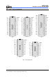
EM78P447N 8-Bit Microcontroller with OTP ROM 3 PIN ASSIGNMENT P55 1 28 /RESET VDD 2 27 OSCI NC 3 26 OSCO TCC 1 2 31 P57 /RESET TCC 3 30 /RESET TCC 2 27 OSCI VDD 4 29 OSCI VDD 3 26 OSCO NC 5 28 OSCO 27 P77 26 P76 25 P75 P77 /INT 4 25 P77 Vss 6 24 P76 P50 5 24 P76 /INT 7 P50 6 23 P75 P51 6 23 P75 P50 8 P51 7 22 P74 P52 7 22 P74 P51 9 P52 8 21 P73 P53 8 21 P73 P52 10 20 P72 P60 9 20 P72 P53 9 P60 P61 19 P71 P6
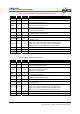
EM78P447N 8-Bit Microcontroller with OTP ROM Table 1 EM78P447NAP and EM78P447NAM Pin Description Symbol Pin No. Type VDD 2 - OSCI 27 I OSCO 26 I/O TCC 1 I /RESET 28 I P50~P53 6~9 I/O P60~P67 10~17 I/O P70~P77 18~25 I/O Function ■ Power supply. ■ ■ ■ ■ ■ ■ XTAL type: Crystal input terminal or external clock input pin. RC type: RC oscillator input pin. XTAL type: Output terminal for crystal oscillator or external clock input pin. RC type: Instruction clock output.
EM78P447N 8-Bit Microcontroller with OTP ROM Table 3 EM78P447NBP and EM78P447NBWM Pin Description Symbol Pin No. Type Function VDD 4 - OSCI 29 I OSCO 28 I/O TCC 3 I /RESET 30 I P50~P57 8~11,2~1, 32~31 I/O P60~P67 12~19 I/O P70~P77 20~27 I/O /INT 7 I ■ External interrupt pin triggered by falling edge. VSS 6 - ■ Ground. NC 5 - ■ No connection. ■ Power supply. ■ ■ ■ ■ ■ ■ XTAL type: Crystal input terminal or external clock input pin. RC type: RC oscillator input pin.
EM78P447N 8-Bit Microcontroller with OTP ROM Table 5 EM78P447NDK and EM78P447NDM Pin Description Symbol Pin No. Type VDD 3 - OSCI 19 I OSCO 18 I/O TCC 2 I /RESET 20 I P50~P54 6~9,1 I/O 10 I/O 11~17 I/O P60 P71~P77 Function ■ Power supply. ■ ■ ■ ■ ■ ■ XTAL type: Crystal input terminal or external clock input pin. RC type: RC oscillator input pin. XTAL type: Output terminal for crystal oscillator or external clock input pin. RC type: Instruction clock output.
EM78P447N 8-Bit Microcontroller with OTP ROM 4.1 Operational Registers 4.1.1 R0 (Indirect Addressing Register) R0 is not a physically implemented register. Its major function is to act as an indirect addressing pointer. Any instruction using R0 as a pointer actually accesses data pointed by the RAM Select Register (R4). 4.1.2 R1 (Time Clock /Counter) Increased by an external signal edge, which is defined by TE bit (CONT-4) through the TCC pin, or by the instruction cycle clock.
EM78P447N 8-Bit Microcontroller with OTP ROM All instruction are single instruction cycle (fclk/2 or fclk/4) except for the instruction that would change the contents of R2. Such instruction will need one more instruction cycle.
EM78P447N 8-Bit Microcontroller with OTP ROM Aaddress R PAGE registers IOC PAGE registers 00 R0 (Indirect Addressing Register) Reserve 01 R1 (Time Clock Counter) 02 R2 (Program Counter) Reserve 03 R3 (Status Register) Reserve 04 R4 (RAM Select Register) Reserve 05 R5 (Port5) IOC5 (I/O Port Control Register) 06 R6 (Port6) IOC6 (I/O Port Control Register) 07 R7 (Port7) IOC7 (I/O Port Control Register) CONT (Control Register) 08 General Register Reserve 09 General Reg
EM78P447N 8-Bit Microcontroller with OTP ROM 4.1.4 R3 (Status Register) 7 6 5 4 3 2 1 0 GP PS1 PS0 T P Z DC C Bit 7 (GP) General read/write bit. Bits 6 (PS1) ~ 5 (PS0) Page select bits. PS1~PS0 are used to pre-select a program memory page. When executing a "JMP", "CALL", or other instructions which causes the program counter to change (e.g. MOV R2, A), PS1~PS0 are loaded into the 11th and 12th bits of the program counter and select one of the available program memory pages.
EM78P447N 8-Bit Microcontroller with OTP ROM 4.1.8 R3F (Interrupt Status Register) Bit 7 Bit 6 Bit 5 Bit 4 Bit 3 Bit 2 Bit 1 Bit 0 - - - - EXIF - - TCIF Bit 3 (EXIF) External interrupt flag. Set by falling edge on /INT pin, flag cleared by software Bit 0 (TCIF) the TCC overflow interrupt flag. Set as TCC overflows; flag cleared by software. Bits 1, 2, 4~7 are not used and read are as “0”. "1" means interrupt request, "0" means non-interrupt.
EM78P447N 8-Bit Microcontroller with OTP ROM Bit 4 (TE) TCC signal edge 0: increment if the transition from low to high takes place on TCC pin 1: increment if the transition from high to low takes place on TCC pin Bit 3 (PAB) Prescaler assignment bit. 0: TCC 1: WDT Bit 2 (PSR2) ~ Bit 0 (PSR0) TCC/WDT prescaler bits.
EM78P447N 8-Bit Microcontroller with OTP ROM 4.2.5 IOCE (WDT Control Register) 7 6 5 4 3 2 1 0 - ODE WDTE SLPC ROC - - /WUE Bit 6 (ODE) Control bit is used to enable the open-drain of P76 and P77 pins 0: Disable open-drain output. 1: Enable open-drain output. The ODE bit can be read and written. Bit 5 (WDTE) Control bit used to enable Watchdog timer. The WDTE bit is useful only when ENWDT, the CODE Option bit, is "0". It is only when the ENWDT bit is "0" that WDTE bit.
EM78P447N 8-Bit Microcontroller with OTP ROM Bit 0 (/WUE) Control bit is used to enable the wake-up function of P74 and P75. 0: Enable the wake-up function. 1: Disable the wake-up function. The /WUE bit can be read and written. Bits 1~2, and 7 Not used. 4.2.6 IOCF (Interrupt Mask Register) 7 6 5 4 3 2 1 0 - - - - EXIE - - TCIE Bit 3 (EXIE) EXIF interrupt enable bit. 0: disable EXIF interrupt 1: enable EXIF interrupt Bit 0 (TCIE) TCIF interrupt enable bit.
EM78P447N 8-Bit Microcontroller with OTP ROM 4.3 TCC/WDT & Prescaler An 8-bit counter is available as prescaler for the TCC or WDT. The prescaler is available for either the TCC or WDT only at any given time, and the PAB bit of the CONT register is used to determine the prescaler assignment. The PSR0~PSR2 bits determine the ratio. The prescaler is cleared each time the instruction is written to TCC under TCC mode.
EM78P447N 8-Bit Microcontroller with OTP ROM 4.4 I/O Ports The I/O registers, Port 5, Port 6, and Port 7, are bi-directional tri-state I/O ports. The functions of Pull-high, R-option, and Open-drain can be performed internally by CONT and IOCE respectively. There is input status change wake-up function on Port 6, P74, and P75. Each I/O pin can be defined as "input" or "output" pin by the I/O control register (IOC5 ~ IOC7). The I/O registers and I/O control registers are both readable and writable.
EM78P447N 8-Bit Microcontroller with OTP ROM 4.5 RESET and Wake-up 4.5.1 RESET A RESET is initiated by one of the following events(1) Power on reset, or (2) /RESET pin input “low”, or (3) WDT timeout. (if enabled) The device is kept in a RESET condition for a period of approx. 18ms3 (one oscillator start-up timer period) after the reset is detected. Once the RESET occurs, the following functions are performed (refer to Fig.8). The oscillator starts or is running The Program Counter (R2) is set to all "1".
EM78P447N 8-Bit Microcontroller with OTP ROM (A) Any of the wake-up pins is “0” as illustrated in Figure. 5. Upon waking, the controller will continue to execute the succeeding address. Under this case, before entering SLEEP2 MODE, the wake-up function of the trigger sources (P60~P67 and P74~P75) should be selected (e.g., input pin) and enabled (e.g., pull-high, wake-up control). It should be noted that after waking up, the WDT is enabled if the Code Option bit ENWDT is “0”.
EM78P447N 8-Bit Microcontroller with OTP ROM NOTE After waking up from the SLEEP2 mode, WDT is automatically enabled. The WDT enabled/disabled operation after waking up from SLEEP2 mode should be appropriately defined in the software. To avoid reset from occurring when the port6 status changed interrupt enters into interrupt vector or is used to wake-up the MCU, the WDT prescaler must be set above 1:1 ratio.
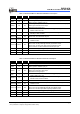
EM78P447N 8-Bit Microcontroller with OTP ROM Address 0x05 0x06 0x07 0x3F Name Reset Type R5(P5) R6(P6) R7(P7) R3F(ISR) Bit 7 Bit 6 Bit 5 Bit 4 Bit 3 Bit 2 Bit 1 Bit 0 P P P P P P P P P57 U P P56 U P P55 U P P54 U P P53 U P P52 U P P51 U P P50 U P P P P P P P P P P67 U P P66 U P P65 U P P64 U P P63 U P P62 U P P61 U P P60 U P P P P P P P P P P77 U P P76 U P P75 U P P74 U P P73 U P P72 U P P71 U P P70 U P P P P P P P P P U U U U U U
EM78P447N 8-Bit Microcontroller with OTP ROM 4.5.2 The Status of RST, T, and P of STATUS Register A RESET condition is initiated by one of the following events: 1. A power-on condition, 2. A high-low-high pulse on /RESET pin, and 3. Watchdog timer time-out. The values of T and P (listed in Table 8 below) are used to verify the event that triggered the processor to wake up. Table 8 shows the events that may affect the status of T and P.
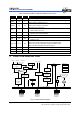
EM78P447N 8-Bit Microcontroller with OTP ROM VDD D CLK Oscillator Q CLK CLR Power-on Reset Voltage Detector WDTE WDT WDT Timeout Setup Time RESET /RESET Fig. 8 Controller Reset Block Diagram 4.6 Interrupt The EM78P447N has two interrupts listed below: (1) TCC overflow interrupt (2) External interrupt (/INT pin). R3F is the interrupt status register that records the interrupt requests in the relative flags/bits. IOCF is the interrupt mask register.
EM78P447N 8-Bit Microcontroller with OTP ROM VCC P R D /IRQn CLK C L Q IRQn INT _ Q RFRD IRQm RF ENI/DISI P R Q IOCF _ Q C L IOD D CLK IOCFWR /RESET IOCFRD RFWR Fig. 9 Interrupt Input Circuit 4.7 Oscillator 4.7.1 Oscillator Modes The EM78P447N can operate in three different oscillator modes, i.e., high XTAL (HXT) oscillator mode, low XTAL (LXT) oscillator mode, and External RC oscillator mode (ERC) oscillator mode.
EM78P447N 8-Bit Microcontroller with OTP ROM Table 11 The Summary of Maximum Operating Speeds Conditions VDD Fxt max.(MHz) 2.3 4.0 3.0 8.0 5.0 20.0 Two cycles with two clocks 4.7.2 Crystal Oscillator/Ceramic Resonators(XTAL) EM78P447N can be driven by an external clock signal through the OSCI pin as shown in Fig. 10 below. In most applications, Pin OSCI and Pin OSCO can be connected with a crystal or ceramic resonator to generate oscillation. Fig. 12 depicts such circuit.
EM78P447N 8-Bit Microcontroller with OTP ROM Table 12 Capacitor Selection Guide for Crystal Oscillator or Ceramic Resonator Oscillator Type Frequency Mode Frequency C1(pF) C2(pF) 455 kHz 100~150 100~150 Ceramic Resonators HXT 2.0 MHz 20~40 20~40 4.0 MHz 10~30 10~30 LXT 32.768kHz 100KHz 25 25 15 25 Crystal Oscillator HXT 200KHz 25 25 455KHz 20~40 20~150 1.0MHz 15~30 15~30 2.0MHz 15 15 4.0MHz 15 15 4.7.
EM78P447N 8-Bit Microcontroller with OTP ROM Table 13 RC Oscillator Frequencies Cext 20 pF 100 pF 300 pF Rext Average Fosc 5V,25°C Average Fosc 3V,25°C 3.3k 5.1k 10k 100k 3.3k 5.1k 10k 100k 3.3k 5.1k 10k 100k 4.32 MHz 2.83 MHz 1.62MHz 184 KHz 1.39 MHz 950 KHz 500 KHz 54KHz 580 KHz 390 KHz 200 KHz 21 KHz 3.56 MHz 2.8 MHz 1.57 MHz 187 KHz 1.35 MHz 930 KHz 490 KHz 55 KHz 550 KHz 380 KHz 200 KHz 21 KHz NOTE 1. Measured on DIP packages. 2. For design reference only. 4.
EM78P447N 8-Bit Microcontroller with OTP ROM Bit 8 (CLKS): Instruction period option bit. 0: two oscillator periods. 1: four oscillator periods. Refer to the section on Instruction Set. Bit 7(ENWDTB): Watchdog timer enable bit. 0: Enable 1: Disable Type selection for EM78P447NA or EM78P447NB Bit 6: 0: EM78P447NB 1: EM78P447NA Bit 5 (HLF): XTAL frequency selection 0: XTAL2 type (low frequency, 32.768KHz) 1: XTAL1 type (high frequency) This bit will affect system oscillation only when Bit4 (OSC) is “1”.
EM78P447N 8-Bit Microcontroller with OTP ROM 4.8.2 Customer ID Register (Word 1) Word 1 Bit 12~Bit 0 XXXXXXXXXXXXX Bit 12~0: Customer’s ID code 4.9 Power On Considerations Any microcontroller is not guaranteed to start and operate properly before the power supply stays at its steady state. EM78P447N is equipped with Power On Voltage Detector(POVD) with a detecting level is 2.0V. It will work well if Vdd rises fast enough (10 ms or less).
EM78P447N 8-Bit Microcontroller with OTP ROM 4.11 Residue-Voltage Protection When battery is replaced, device power (Vdd) is taken off but residue-voltage remains. The residue-voltage may trips below Vdd minimum, but not to zero. This condition may cause a poor power on reset. Fig.16 and Fig.17 show how to build the residue-voltage protection circuit. Vdd Vdd 33K EM78P447N Q1 10K /RESET 40K 1N4684 Fig. 14 The Residue Voltage Protection Circuit 1 Vdd Vdd R1 EM78P447N Q1 /RESET 40K R2 Fig.
EM78P447N 8-Bit Microcontroller with OTP ROM 4.12 Instruction Set Each instruction in the instruction set is a 13-bit word divided into an OP code and one or more operands. Normally, all instructions are executed within one single instruction cycle (one instruction consists of 2 oscillator periods), unless the program counter is changed by instruction "MOV R2,A", "ADD R2,A", or by instructions of arithmetic or logic operation on R2 (e.g. "SUB R2,A", "BS(C) R2,6", "CLR R2", ⋅⋅⋅⋅).
EM78P447N 8-Bit Microcontroller with OTP ROM INSTRUCTION BINARY HEX MNEMONIC OPERATION STATUS AFFECTED 0 0000 0000 000 0000 NOP No Operation None 0 0000 0000 001 0001 DAA Decimal Adjust A C 0 0000 0000 010 0002 CONTW A → CONT None 0 0000 0000 011 0003 SLEP 0 → WDT, Stop oscillator T,P 0 0000 0000 100 0004 WDTC 0 → WDT T,P 0 0000 0000 rrrr 000r IOW R A → IOCR None 0 0000 0001 000 0010 ENI Enable Interrupt None 0 0000 0001 001 0011 DISI Disable Interrupt No
EM78P447N 8-Bit Microcontroller with OTP ROM INSTRUCTION BINARY HEX 0 0101 10rr rrrr 05rr DJZA R R-1 → A, skip if zero None 0 0101 11rr rrrr 05rr DJZ R R-1 → R, skip if zero None 0 0110 00rr rrrr 06rr RRCA R 0 0110 01rr rrrr 06rr RRC R 0 0110 10rr rrrr 06rr RLCA R 0 0110 11rr rrrr 06rr RLC R 0 0111 00rr rrrr 07rr SWAPA R 0 0111 01rr rrrr 07rr SWAP R R(0-3) ↔ R(4-7) None 0 0111 10rr rrrr 07rr JZA R R+1 → A, skip if zero None 0 0111 11rr rrrr 07rr JZ R R+1 → R, skip if
EM78P447N 8-Bit Microcontroller with OTP ROM 4.13 Timing Diagram AC Test Input/O utput W aveform 2.4 2.0 0.8 TE S T P O IN TS 2.0 0.8 0.4 AC T estin g : In p u t is d riven at 2.4V fo r lo g ic "1",an d 0.4V fo r lo g ic "0".T im in g m easu rem en ts are m ad e at 2.0V fo r lo g ic "1",an d 0.8V fo r lo g ic "0". R E S E T Tim ing (C LK ="0") NOP Instruction 1 E xecuted CLK /R ESET T d rh TC C Input Tim ing (C LK S ="0") T in s C LK TCC T tcc Product Specification (V1.1) 03.30.
EM78P447N 8-Bit Microcontroller with OTP ROM 5 ABSOLUTE MAXIMUM RATINGS Items 6 Rating Temperature under bias -40°C to Storage temperature -65°C to 150°C Input voltage VSS-0.3V to VDD+0.5V Output voltage VSS-0.3V to VDD+0.5V 85°C Operating Frequency (2clk) 32.768KHz to 20MHz Operating Voltage 2.5V to 5.5V DC ELECTRICAL CHARACTERISTICS 6.1 DC Electrical Characteristic (Ta= 25 °C, VDD= 5.
EM78P447N 8-Bit Microcontroller with OTP ROM Symbol Parameter ISB2 Power down current ICC1 Operating supply current (VDD=3V) at two cycles/four clocks ICC2 Operating supply current (VDD=3V) at two cycles/four clocks ICC3 Operating supply current (VDD=5V) at two cycles/two clocks ICC4 Operating supply current (VDD=5V) at two cycles/four clocks Condition Min Typ.
EM78P447N 8-Bit Microcontroller with OTP ROM 6.3 Device characteristic The graphic provided in the following pages were derived based on a limited number of samples and are shown here for reference only. The device characteristic illustrated herein are not guaranteed for it accuracy. In some graphic, the data maybe out of the specified warranted operating range. Vih/Vil (Input pins with schmitt inverter) 2 Vih max(-40℃ to 85℃ ) Vih typ 25℃ Vih min(-40℃ to 85℃) Vih Vil(Volt) 1.
EM78P447N 8-Bit Microcontroller with OTP ROM Voh/Ioh (VDD=5V) 0 -5 Ioh(mA) -10 Min 85 ℃ -15 Typ 25 ℃ -20 Max -40 ℃ -25 0 1 2 3 4 5 Voh(Volt) Fig.18 Port5, Port6, and Port7 Voh vs. Ioh,VDD=5V Product Specification (V1.1) 03.30.
EM78P447N 8-Bit Microcontroller with OTP ROM Voh/Ioh (VDD=3V) 0 -2 Min 85 ℃ Ioh(mA) -4 Typ 25 ℃ -6 Max -40 ℃ -8 -10 0 0.5 1 1.5 2 2.5 3 Voh(Volt) Fig.19 Port5, Port6, and Port7 Voh vs. Ioh, VDD=3V 38 • Product Specification (V1.1) 03.30.
EM78P447N 8-Bit Microcontroller with OTP ROM Vol/Iol (VDD=5V) 90 Max -40 ℃ 80 70 Typ 25 ℃ Iol(mA) 60 Min 85 ℃ 50 40 30 20 10 0 0 1 2 3 4 5 6 Vol(Volt) Fig. 20 Port5, and Port6 Vol vs, Iol, VDD=5V Product Specification (V1.1) 03.30.
EM78P447N 8-Bit Microcontroller with OTP ROM Vol/Iol (VDD=3V) 40 Max -40 ℃ 35 30 Typ 25 ℃ Iol(mA) 25 Min 85 ℃ 20 15 10 5 0 0 0.5 1 1.5 2 2.5 3 Vol(Volt) Fig. 21 Port5, and Port6 Vol vs. Iol, VDD=3V 40 • Product Specification (V1.1) 03.30.
EM78P447N 8-Bit Microcontroller with OTP ROM Vol/Iol (5V) 100 Max -40 ℃ 90 80 Typ 25 ℃ 70 Iol(mA) 60 Min 85 ℃ 50 40 30 20 10 0 0 1 2 3 4 5 6 Vol(Volt) Fig. 22 Port7 Vol vs. Iol, VDD=5V Product Specification (V1.1) 03.30.
EM78P447N 8-Bit Microcontroller with OTP ROM Vol/Iol (3V) 45 Max -40 ℃ 40 35 Typ 25 ℃ Iol(mA) 30 25 Min 85 ℃ 20 15 10 5 0 0 0.5 1 1.5 2 2.5 3 Vol(Volt) Fig. 23 Port7 Vol vs. Iol, VDD=3V 42 • Product Specification (V1.1) 03.30.
EM78P447N 8-Bit Microcontroller with OTP ROM WDT Time_out 35 30 WDT period (mS) 25 Max 85 ℃ 20 Max 75 ℃ Typ 25 ℃ 15 Min 0 ℃ Min -40 ℃ 10 5 0 2 3 4 5 VDD (Volt) 6 Fig. 24 WDT Time Out Period vs. VDD, Prescaler Set to 1 : 1 Product Specification (V1.1) 03.30.
EM78P447N 8-Bit Microcontroller with OTP ROM Cext=100pF, Typical RC OSC Frequency 1.4 R=3.3k Frequency(M Hz) 1.2 1 R=5.1k 0.8 0.6 R=10k 0.4 0.2 R=100k 0 2.5 3 3.5 4 4.5 VDD(Volt) 5 5.5 Fig. 25 Typical RC OSC Frequency vs. VDD (Cext=100pF, Temperature at 25 ℃) 44 • Product Specification (V1.1) 03.30.
EM78P447N 8-Bit Microcontroller with OTP ROM ERC OSC Frequency vs Temp.(Cext=100pF, Rext=5.1K) 1.005 Fosc/Fosc(25℃) 1 0.995 3V 0.99 5V 0.985 0.98 -40 -20 0 20 40 60 80 Temperature(℃) Fig. 26 Typical RC OSC Frequency vs. Temperature(R and C are ideal component) Four conditions exist with the operating current ICC1 to ICC4. these conditions are as follows: ICC1:VDD=3V, Fosc=32 kHz, 2clock, WDT disable. ICC2:VDD=3V, Fosc=32 kHz, 2clock, WDT enable. ICC3:VDD=5V, Fosc=4 MHz, 2clock, WDT enable.
EM78P447N 8-Bit Microcontroller with OTP ROM Maximum ICC1 and ICC2 vs. Temperature 27 Current (uA) Max ICC2 24 Max ICC1 21 18 15 -40 -20 0 20 40 60 80 Temperature (℃) Fig. 28 Maximum Operating Current(ICC1 and ICC2) vs. Temperature Current (mA) Typical ICC3 and ICC4 vs. Temperature 4 3.5 3 2.5 2 1.5 1 0.5 Typ ICC4 Typ ICC3 -40 -20 0 20 40 60 80 Temperature (℃) Fig. 29 Typical Operating Current(ICC3 and ICC4) vs. Temperature 46 • Product Specification (V1.1) 03.30.
EM78P447N 8-Bit Microcontroller with OTP ROM Maximum ICC3 and ICC4 vs. Temperature 4.5 Current (mA) 4 Max ICC4 3.5 3 Max ICC3 2.5 2 1.5 1 -40 -20 0 20 40 60 80 Temperature (℃) Fig. 30 Maximum Operating Current(ICC3 and ICC4) vs. Temperature Two conditions exist with the standby current ISB1 and ISB2. these conditions are as follow: ISB1:VDD=5V, WDT disable ISB2:VDD=5V, WDT enable Typical ISB1 and ISB2 vs.
EM78P447N 8-Bit Microcontroller with OTP ROM Maximum ISB1 and ISB2 vs. Temperature 15 Current (uA) 12 Max ISB2 9 6 3 Max ISB1 0 -40 -20 0 20 40 60 80 Temperature (℃) Fig. 32 Maximum Standby Current(ISB1 and ISB2) vs. Temperature Operating voltage (-40℃~85℃) Frequency (M Hz) 25 20 15 10 5 0 2 2.5 3 3.5 4 4.5 5 5.5 6 VDD (Volt) Fig. 33 Operating Voltage In Temperature Range from -40 ℃ to 85 ℃ 48 • Product Specification (V1.1) 03.30.
EM78P447N 8-Bit Microcontroller with OTP ROM EM78P447N HXT I-V 3 2.5 I(mA) 2 1.5 Max 1 Min 0.5 0 0 1 2 3 4 5 6 Volt(V) Fig. 34 EM78P447N I-V Curve Operating at 4 MHz EM78P447N LXT I-V 40 35 30 I(uA) 25 Max 20 15 Min 10 5 0 0 1 2 3 4 5 6 Volt(V) Fig. 35 EM78P447N I-V Curve Operating at 32.768 kHz Product Specification (V1.1) 03.30.
EM78P447N 8-Bit Microcontroller with OTP ROM APPENDIX A Package Types Package Type Pin Count Package Size EM78P447NCP OTP MCU DIP 20 300 mil EM78P447NCM SOP 20 300 mil EM78P447NDK Skinny DIP 24 300 mil EM78P447NDM SOP 24 300 mil EM78P447NAP DIP 28 600 mil EM78P447NAM SOP 28 300 mil EM78P447NAS SSOP 28 209 mil EM78P447NBP DIP 32 600 mil EM78P447NBWM SOP 32 450 mil B Package Information 20-Lead plastic dual inline package(DIP)- 300 mil Symbal A A1 A2 c D E1 E eB B B1 L
EM78P447N 8-Bit Microcontroller with OTP ROM 24-Lead plastic dual inline skinny package(DIP)- 300 mil 13 24 E 12 Min 0.381 3.175 0.203 31.750 6.426 7.370 8.380 0.356 1.470 3.048 0 Normal Max 5.334 3.302 3.429 0.254 0.356 31.801 31.852 6.628 6.830 7.620 7.870 8.950 9.520 0.457 0.559 1.520 1.630 3.302 3.556 2.
EM78P447N 8-Bit Microcontroller with OTP ROM 32-Lead plastic dual inline package(DIP)- 600 mil 20-Lead plastic small outline package(SOP)- 300 mil Symbal A A1 b c E H D L e θ b Min 2.350 0.102 Normal Max 2.650 0.300 0.406(TYP) 0.230 7.400 10.000 12.600 0.630 0 0.838 1.27(TYP) 0.320 7.600 10.650 12.900 1.100 8 e c TITLE: SOP-20L(300MIL) PACKAGE OUTLINE DIMENSION File : SO20 Edtion: A Unit : mm Scale: Free Material: Sheet:1 of 1 52 • Product Specification (V1.1) 03.30.
EM78P447N 8-Bit Microcontroller with OTP ROM 24-Lead plastic small outline package(SOP)- 300 mil Symbal A A1 b c E H D L e θ b Min 2.350 0.102 Normal Max 2.650 0.300 0.406(TYP) 0.230 7.400 10.000 15.200 0.630 0 0.838 1.27(TYP) 0.320 7.600 10.650 15.600 1.100 8 e c TITLE: SOP-24L(300MIL) PACKAGE OUTLINE DIMENSION File : SO24 Edtion: A Unit : mm Scale: Free Material: Sheet:1 of 1 28-Lead plastic small outline package(SOP)- 300 mil Product Specification (V1.1) 03.30.
EM78P447N 8-Bit Microcontroller with OTP ROM 32-Lead plastic small outline package(SOP)- 300 mil 28-Lead Shrink Small Outline Package(SSOP)- 209 mil 54 • Product Specification (V1.1) 03.30.