User Guide Types 8131, 8137, 8138 Types 8122, 8123, 8124
User Guide Types 8131, 8137, 8138 Types 8122, 8123, 8124
Note Before using this information and the product it supports, be sure to read the “Important safety information” on page v and Appendix D, “Notices,” on page 43. Third Edition (May 2006) © Copyright International Business Machines Corporation 2006. All rights reserved. US Government Users Restricted Rights – Use, duplication or disclosure restricted by GSA ADP Schedule Contract with IBM Corp.
Contents Important safety information . . . . . . v Conditions that require immediate action . . . . . v General safety guidelines . . . . . . . . . . vi Service . . . . . . . . . . . . . . . vi Power cords and power adapters . . . . . . vii Extension cords and related devices . . . . . vii Plugs and outlets . . . . . . . . . . . viii Batteries . . . . . . . . . . . . . . viii Heat and product ventilation . . . . . . . ix CD and DVD drive safety . . . . . . . . . ix Additional safety information. . . . . .
iv User Guide
Important safety information Note Please read important safety information first. This information can help you safely use your ThinkCentre® or ThinkPad® personal computer. Follow and retain all information included with your computer. The information in this document does not alter the terms of your purchase agreement or the Lenovo™ Statement of Limited Warranty. Customer safety is important. Our products are developed to be safe and effective. However, personal computers are electronic devices.
unplug it from the power source and telecommunication lines until you can speak to the Customer Support Center for further guidance. See “Information resources” on page xiii. v Power cords, plugs, power adapters, extension cords, surge protectors, or power supplies that are cracked, broken or damaged. v Signs of overheating, smoke, sparks or fire. v Damage to a battery (such as cracks, dents, creases), discharge from a battery, or a buildup of foreign substances on the battery.
Danger Hazardous moving parts. Keep fingers and other body parts away. Attention Before replacing any CRUs, turn off the computer and wait three to five minutes to let the computer cool before opening the cover. Power cords and power adapters Use only the power cords and power adapters supplied by the product manufacturer. Never wrap a power cord around the power adapter or other object. Doing so can stress the cord in ways that can cause the cord to fray, crack or crimp.
product. Never overload these devices. If power strips are used, the load should not exceed the power strip input rating. Consult an electrician for more information if you have questions about power loads, power requirements, and input ratings. Plugs and outlets If a receptacle (power outlet) that you intend to use with your computer equipment appears to be damaged or corroded, do not use the outlet until it is replaced by a qualified electrician. Do not bend or modify the plug.
Heat and product ventilation Computers generate heat when turned on and when batteries are charging. Notebook PCs can generate a significant amount of heat due to their compact size. Always follow these basic precautions: v Do not leave the base of your computer in contact with your lap or any part of your body for an extended period when the computer is functioning or when the battery is charging. Your computer produces some heat during normal operation.
v Check CD/DVD discs for cracks before each use. Do not use cracked or damaged discs Additional safety information Danger Electrical current from power, telephone, and communication cables is hazardous. To avoid a shock hazard: v Do not connect or disconnect any cables or perform installation, maintenance, or reconfiguration of this product during an electrical storm. v Connect all power cords to a properly wired and grounded electrical outlet.
Modem safety information Caution To reduce the risk of fire, use only No. 26 AWG or larger telecommunication line cord. To reduce the risk of fire, electrical shock, or injury when using telephone equipment, always follow basic safety precautions, such as: v Never install telephone wiring during a lightning storm. v Never install telephone jacks in wet locations unless the jack is specifically designed for wet locations.
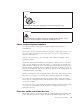
Power supply statement Never remove the cover on a power supply or any part that has the following label attached. Hazardous voltage, current, and energy levels are present inside any component that has this label attached. There are no serviceable parts inside these components. If you suspect a problem with one of these parts, contact a service technician.
Overview Thank you for selecting this computer. Your computer incorporates many of the latest advances in computer technology and can be upgraded as your needs change. Adding hardware options to your computer is an easy way to increase its capabilities. Instructions for installing external and internal options are included in this publication. When adding an option, use these instructions along with the instructions that come along with the option.
xiv User Guide
Chapter 1. Installing options This chapter provides an introduction to the features and options that are available for your computer. You can expand the capabilities of your computer by adding memory, adapters, or drives. When installing an option, use these instructions along with the instructions that come with the option. Important Before you install or remove any option, read “Important safety information” on page v. These precautions and guidelines will help you work safely.
Memory v Support for four double data rate 2 (DDR2) dual inline memory modules (DIMM) v 512 KB flash memory for system programs Internal drives v 3.5-inch, slim, 1.
Expansion v Four drive bays v Two standard PCI adapter connectors v One PCI Express (x1) adapter connector v One PCI Express (x16) graphics adapter connector (some models) Power v 230 W power supply with manual voltage selection switch (some models) v 310 W power supply with manual voltage selection switch (some models) v Automatic 50/60 Hz input frequency switching v Advanced Configuration and Power Interface (ACPI) support Security features v User and administrator passwords for BIOS access v User and mas
Specifications This section lists the physical specifications for your computer. Dimensions Height: 432 mm (17.0 in.) Width: 178 mm (7.0 in.) Minimum configuration: 256 Btu/hr (75 watts) Depth: 450 mm (17.7 in.) Maximum configuration: 1058 Btu/hr (310 watts) Airflow Weight Minimum configuration: 10.5 kg (23 lb) Maximum configuration: 13.
Available options The following are some available options: v External options – Parallel port devices, such as printers and external drives – Serial port devices, such as external modems and digital cameras – Audio devices, such as external speakers for the sound system – USB devices, such as printers, joysticks, and scanners – Security device, such as a padlock or integrated cable lock – Monitors – IEEE 1394 devices (requires an IEEE 1394 adapter) v Internal options – System memory – – – – PCI adapters P
Handling static-sensitive devices Static electricity, although harmless to you, can seriously damage computer components and options. When you add an option, do not open the static-protective package containing the option until you are instructed to do so. When you handle options and other computer components, take these precautions to avoid static electricity damage: v Limit your movement. Movement can cause static electricity to build up around you. v Always handle components carefully.
Locating the connectors on the front of your computer The following illustration shows the locations of the connectors on the front of the computer. Note: Not all computer models will have the following connectors. 1 3 9 4 1 2 3 IEEE 1394 connector (some models) 4 USB connector 5 USB connector Microphone connector Headphone connector Chapter 1.
Locating the connectors on the rear of your computer The following illustration shows the locations of the connectors on the rear of the computer.
Connector Description Audio line in connector Used to receive audio signals from an external audio device, such as a stereo system. When you attach an external audio device, a cable is connected between the audio line out connector of the device and the audio line in connector of the computer.
Removing the cover Important Read “Important safety information” on page v and “Handling static-sensitive devices” on page 6 before removing the cover. To remove the cover: 1. Shut down your operating system, remove any media (diskettes, CDs, or tapes) from the drives, and turn off all attached devices and the computer. 2. Unplug all power cords from electrical outlets. 3. Disconnect all cables attached to the computer.
Locating components The following illustration will help you locate the various components in your computer. 1 2 3 4 5 6 7 8 9 Optical drive Memory modules Power supply PCI adapter connector PCI adapter card System board Hard disk drive Internal speaker Diskette drive Chapter 1.
Identifying parts on the system board The system board (sometimes called the planar or motherboard) is the main circuit board in your computer. It provides basic computer functions and supports a variety of devices that are factory-installed or that you can install later. The following illustration shows the locations of parts on the system board.
Installing memory Your computer has four connectors for installing dual inline memory modules (DIMMs) that provide up to a maximum of 4.0 GB of system memory. When installing DDR2 type memory modules, the following rules apply: v Use 1.8 V, 240-pin DDR2 synchronous dynamic random access memory (SDRAM). v Use 256 MB, 512 MB or 1.0 GB memory modules in any combination. To install a memory module: 1. Remove the cover. See “Removing the cover” on page 10. 2. Locate the memory connectors.
Installing adapters This section provides information and instructions for installing and removing adapters. Your computer has two expansion connectors for PCI adapters, one for a PCI Express (x1) adapter, and one for a PCI Express (x16) adapter. To install an adapter: 1. Remove the cover. See “Removing the cover” on page 10. 2. Push the adapter latch and remove the slot cover for the appropriate PCI connector. 3. Remove the adapter from its static-protective package. 4.
What to do next v To work with another option, go to the appropriate section. v To complete the installation, go to “Replacing the cover and connecting the cables” on page 25. Installing internal drives This section provides information and instructions for installing and removing internal drives. Internal drives are devices that your computer uses to read and store data. You can add drives to your computer to increase storage capacity and to enable your computer to read other types of media.
The following illustration shows the locations of the drive bays. The following list describes the types and size of drives you can install in each bay: 1 Bay 1 - Maximum height: 43.0 mm (1.7 in.) 2 Bay 2 - Maximum height: 43.0 mm (1.7 in.) 3 Bay 3 - Maximum height: 25.8 mm (1.0 in.) 4 Bay 4 - Maximum height: 25.8 mm (1.0 in.) v Optical drive such as CD drive or DVD drive (preinstalled in some models) v 5.25-inch hard disk drive v 3.5-inch hard disk drive (requires a Universal Adapter Bracket, 5.
Installing a drive in bay 1 or bay 2 To install a drive in bay 1 or bay 2, follow these steps: 1. Remove the cover. See “Removing the cover” on page 10. 2. Remove the front bezel by pressing downward on the plastic tabs 1 and pulling the bezel as shown. 3. Remove the static shield from the drive bay by using a flat-blade screwdriver to gently pry it loose. 4. Remove the plastic panel in the bezel for bay 1 or 2 by squeezing the plastic tabs that secure the panel on the inside of the bezel. Chapter 1.
5. If you are installing any type of drive other than a serial ATA hard disk drive, make sure the drive that you are installing is set correctly as either a master or a slave device. Note: A serial ATA hard disk drive does not need to be set as either a master or a slave device. v If it is the first CD drive or DVD drive, set it as a master device. v If it is an additional CD drive or DVD drive, set it as a slave device. v If it is an additional parallel ATA hard disk drive, set it as a slave device.
9. Install the front bezel by aligning the plastic tabs on the bottom of the bezel with the corresponding holes in chassis and press it onto the chassis until it snaps into position. 10. Continue at “Connecting drives.” Connecting drives The steps to connect a drive are different depending on the type of drive. Use one of the following procedures for your drive connection. Connecting the first optical drive 1.
Connecting an additional optical drive, or parallel ATA hard disk drive 1. Locate the extra connector on the three-connector signal cable that is attached to the PATA IDE connector on the system board. See “Identifying parts on the system board” on page 12. 2. Connect the extra connector on the signal cable to the new drive. 3. Locate the extra four-wire power connector and connect it to the drive.
Installing security features To help prevent hardware theft and unauthorized access to your computer, several security lock options are available. The following sections will help you identify and install the various types of locks that might be available for your computer. In addition to physical locks, unauthorized use of your computer can be prevented by a software lock that locks the keyboard until a correct password is typed in.
Padlock Your computer is equipped with a padlock loop such that the cover cannot be removed when a padlock is installed.
Integrated cable lock With an integrated cable lock (sometimes referred to as a Kensington lock), you can secure your computer to a desk, table, or other non-permanent fixture. This lock also secures the computer cover. The cable lock attaches to a security slot at the rear of your computer and is operated with a key. This is the same type of lock used with many laptop computers. You can order a cable lock directly from Lenovo. Go to http://www.lenovo.com.think/support and search on Kensington.
configuration information (including passwords) are lost. An error message is displayed when you turn on the computer. Refer to “Lithium battery notice” on page x for information about replacing and disposing of the battery. To change the battery: 1. Turn off the computer and all attached devices. 2. Remove the cover. See “Removing the cover” on page 10. 3. Locate the battery. See “Identifying parts on the system board” on page 12. 4. If necessary, remove any adapters that impede access to the battery.
5. Move the jumper from the standard position (pins 1 and 2) to the maintenance or configure position (pins 2 and 3). 6. Replace the cover and connect the power cord. See “Replacing the cover and connecting the cables.” 7. Restart the computer, leave it on for approximately ten seconds. Turn off the computer by holding the power switch for approximately five seconds. The computer will turn off. 8. Repeat steps 2 through 4 on page 24. 9. Move the jumper back to the standard (pins 1 and 2). 10.
26 User Guide
Chapter 2. Using the Setup Utility program The Setup Utility program is stored in the electrically erasable programmable read-only memory (EEPROM) of your computer. The Setup Utility program is used to view and change the configuration settings of your computer, regardless of which operating system you are using. However, the operating-system settings might override any similar settings in the Setup Utility program. Starting the Setup Utility program To start the Setup Utility program, do the following: 1.
Administrator Password Setting an Administrator Password deters unauthorized persons from changing configuration settings. If you are responsible for maintaining the settings of several computers, you might want to set an Administrator Password. After you set an Administrator Password, a password prompt is displayed each time you try to access the Setup Utility program. If you type the wrong password, you will see an error message.
Selecting a startup device If your computer does not start up (boot) from a device such as the CD-ROM, diskette, or hard disk as expected, use one of the following procedures to select a startup device. Selecting a temporary startup device Use this procedure to startup from any boot device. Note: Not all CDs, hard disks, and diskettes are startable (bootable). 1. Turn off your computer. 2. Press and hold the F12 key then turn on the computer. When the Startup Device Menu appears, release the F12 key.
30 User Guide
Appendix A. Updating system programs This appendix contains information about updating system programs and how to recover from a POST/BIOS update failure. System programs System programs are the basic layer of software that is built into your computer. They include the power-on self-test (POST), the basic input/output system (BIOS) code, and the Setup Utility program. POST is a set of tests and procedures that is performed each time you turn on your computer.
1. From your browser, type http://www.lenovo.com/think/support in the address field and press Enter. 2. Locate the Downloadable files for your machine type as follows: a. Under Use Quick path, type your machine type and click Go. Click Continue. Click Downloads and drivers. Under the BIOS category, click the Flash BIOS update. Click the .txt file that contains the installation instructions for the flash BIOS update (flash from the operating system version). 3. Print these instructions.
Appendix B. Cleaning the mouse This appendix provides instructions on how to clean your mouse. The procedure will be different depending on which type of mouse you have. Cleaning an optical mouse If you experience some problems with your optical mouse, check the following: 1. Turn the mouse over and look carefully at the lens area. a. If there is a smudge on the lens, gently clean the area with a plain cotton-tipped swab. b. If there is some debris in the lens, gently blow the debris away from the area. 2.
3. Place your hand over the retainer ring and ball 2 , and then turn the mouse over, top side up, so that the retainer ring and ball fall out into your hand. 4. Wash the ball in warm, soapy water then dry it with a clean cloth. Blow air carefully into the ball cage 4 to dislodge dust and lint. 5. Look for a build up of dirt on the plastic rollers 3 inside the ball cage. This build up usually appears as a stripe running across the middle of the rollers. 6.
Appendix C. Manual modem commands The following section lists commands for manually programming your modem. Commands are accepted by the modem while it is in Command Mode. Your modem is automatically in Command Mode until you dial a number and establish a connection. Commands can be sent to your modem from a PC running communication software or any other terminal devices. All commands sent to the modem must begin with AT and end with ENTER.
Command Function H1 Force modem off-hook (make busy) Note: H1 command is not supported for Italy I_ L_ M_ I0 Display product-identification code I1 Factory ROM checksum test I2 Internal memory test I3 Firmware ID I4 Reserved ID L0 Low speaker volume L1 Low speaker volume L2 Medium speaker volume L3 High speaker volume M0 Internal speaker off M1 Internal speaker on until carrier detected M2 Internal speaker always on M3 Internal speaker on until carrier detected and off while d
Extended AT commands Command Function &C0 Force Carrier Detect Signal High (ON) &C1 Turn on CD when remote carrier is present &D0 Modem ignores the DTR signal &D1 Modem returns to Command Mode after DTR toggle &D2 Modem hangs up, returns to the Command Mode after DTR toggle &D3 Resets modem after DTR toggle &F_ &F Recall factory default configuration &G_ &G0 Guard tone disabled &G1 Guard tone disabled &G2 1800 Hz guard tone &K0 Disable flow control &K3 Enable RTS/CTS hardware flow
Command Function &W_ %E_ &V1 Display Last Connection Statistics &W0 Stores the active profile as Profile 0 &W1 Stores the active profile as Profile 1 %E0 Disable auto-retrain %E1 Enable auto-retrain +MS? Displays the current Select Modulation settings +MS=? Displays a list of supported Select Modulation options +MS=a,b,c,e,f Select modulation where: a=0, 1, 2, 3, 9, 10, 11, 12, 56, 64, 69; b=0-1; c=300-56000; d=30056000; e=0-1; and f=0-1. A, b, c, d, e, f default=12, 1, 300, 56000, 0, 0.
Fax Class 1 commands +FAE=n Data/Fax Auto Answer +FCLASS=n Service Class +FRH=n Receive data with HDLC framing +FRM=n Receive data +FRS=n Receive silence +FTH=n Transmit data with HDLC framing +FTM=n Transmit data +FTS=n Stop transmission and wait Fax Class 2 commands +FCLASS=n Services class. +FAA=n Adaptive answer. +FAXERR Fax error value. +FBOR Phase C data bit order. +FBUF? Buffer size (read only). +FCFR Indicate confirmation to receive. +FCLASS= Service class.
+FPHCTO Phase C time out. +FPOLL Indicates polling request. +FPTS: Page transfer status. +FPTS= Page transfer status. +FREV? Identify revision. +FSPT Enable polling. +FTSI: Report the transmit station ID.
Attention Switzerland User: If your Swisscom phone line does not have Taxsignal switched OFF, modem function may be impaired. The impairment may be resolved by a filter with the following specifications: Telekom PTT SCR-BE Taximpulssperrfilter-12kHz PTT Art. 444.112.7 Bakom 93.0291.Z.N Appendix C.
42 User Guide
Appendix D. Notices Lenovo may not offer the products, services, or features discussed in this document in all countries. Consult your local Lenovo representative for information on the products and services currently available in your area. Any reference to a Lenovo product, program, or service is not intended to state or imply that only that Lenovo product, program, or service may be used.
vary significantly. Some measurements may have been made on development-level systems and there is no guarantee that these measurements will be the same on generally available systems. Furthermore, some measurements may have been estimated through extrapolation. Actual results may vary. Users of this document should verify the applicable data for their specific environment. Television output notice The following notice applies to models that have the factory-installed television-output feature.
Index A adapters installing 14 peripheral component interconnect (PCI) slots 14 audio line in connector 9 audio line out connector 9 audio, subsystem 2 B K keyboard connector 9 M battery location 12 boot-block recovery 32 memory dual inline memory modules (DIMMs) installing 13 system 13 memory modules, installing 13 microphone connector 9 modem commands Basic AT 35 Extended AT 37 Fax Class 1 39 Fax Class 2 39 MNP/V.42/V.42bis/V.
S security features 3, 21 hard disk drive 27 integrated cable lock 22, 23 security profile by device 28 serial connector 9 Setup Utility program 27 system board connectors 12 identifying parts 12 location 12 memory 5, 12 system programs 31 U USB connectors 9 using passwords 27 security profile by device 28 Setup Utility program 27 V video, subsystem 46 User Guide 2
Part Number: 39J7710 Printed in USA (1P) P/N: 39J7710