ThinkCentre™ User Guide Types 8128, 8185, 8186, 8187, 8188 Types 8189, 8190, 8192, 8193, 8194 Types 8195, 8196, 8197, 8413, 8414 Types 8415, 8430, 8431, 8432, 8433
ThinkCentre™ User Guide Types 8128, 8185, 8186, 8187, 8188 Types 8189, 8190, 8192, 8193, 8194 Types 8195, 8196, 8197, 8413, 8414 Types 8415, 8430, 8431, 8432, 8433
Note Before using this information and the product it supports, be sure to read the “Important safety information” on page v and Appendix E, “Notices,” on page 117. Fourth Edition (August 2004) © Copyright International Business Machines Corporation 2004. All rights reserved. US Government Users Restricted Rights – Use, duplication or disclosure restricted by GSA ADP Schedule Contract with IBM Corp.
Contents Important safety information . . . . . . v Conditions that require immediate action . . . . . v General safety guidelines . . . . . . . . . . vi Service . . . . . . . . . . . . . . . vi Power cords and power adapters . . . . . . vi Extension cords and related devices . . . . . vii Plugs and outlets . . . . . . . . . . . vii Batteries . . . . . . . . . . . . . . vii Heat and product ventilation . . . . . . . viii CD and DVD drive safety . . . . . . . . viii Additional safety information . . . . . .
Replacing the cover and connecting the cables . . . 70 Chapter 4. Types 8189, 8190, 8194, 8195, 8415, 8432, and 8433 . . . . . . 73 Features . . . . . . . . . . . . . Specifications . . . . . . . . . . . . Available options . . . . . . . . . . Tools required . . . . . . . . . . . Handling static-sensitive devices . . . . . Installing external options . . . . . . . Locating the connectors on the front of your computer . . . . . . . . . . . . Locating the connectors on the rear of your computer . . . . . .
Important safety information This information can help you safely use your IBM® personal computer. Follow and retain all information included with your IBM computer. The information in this document does not alter the terms of your purchase agreement or the IBM Statement of Limited Warranty. Customer safety is important to IBM. Our products are developed to be safe and effective. However, personal computers are electronic devices.
v Damage to a battery (such as cracks, dents, creases), discharge from a battery, or a buildup of foreign substances on the battery. v A cracking, hissing or popping sound, or strong odor that comes from the product. v Signs that liquid has been spilled or an object has fallen onto the computer product, the power cord or power adapter. v The computer product, the power cord or power adapter has been exposed to water. v The product has been dropped or damaged in any way.
Do not use any power adapter that shows corrosion at the ac input pins and/or shows signs of overheating (such as deformed plastic) at the ac input or anywhere on the power adapter. Do not use any power cords where the electrical contacts on either end show signs of corrosion or overheating or where the power cord appears to have been damaged in any way.
foreign materials on the battery leads, stop using the battery and obtain a replacement from the battery manufacturer. Batteries can degrade when they are left unused for long periods of time. For some rechargeable batteries (particularly Lithium Ion batteries), leaving a battery unused in a discharged state could increase the risk of a battery short circuit, which could shorten the life of the battery and can also pose a safety hazard.
Additional safety information DANGER Electrical current from power, telephone, and communication cables is hazardous. To avoid a shock hazard: v Do not connect or disconnect any cables or perform installation, maintenance, or reconfiguration of this product during an electrical storm. v Connect all power cords to a properly wired and grounded electrical outlet. v Connect to properly wired outlets any equipment that will be attached to this product.
v Lorsque vous installez, que vous déplacez, ou que vous manipulez le présent produit ou des périphériques qui lui sont raccordés, reportez-vous aux instructions ci-dessous pour connecter et déconnecter les différents cordons. Connexion: Déconnexion: 1. Mettez les unités hors tension. 1. Mettez les unités hors tension. 2. Commencez par brancher tous les cordons sur les unités. 2. Débranchez les cordons d’alimentation des prises. 3. Branchez les câbles d’interface sur des connecteurs. 3.
v Never touch uninsulated telephone wires or terminals unless the telephone line has been disconnected at the network interface. v Use caution when installing or modifying telephone lines. v Avoid using a telephone (other than a cordless type) during an electrical storm. There may be a remote risk of electric shock from lightning. v Do not use the telephone to report a gas leak in the vicinity of the leak.
DANGER: Certains modèles d’ordinateurs personnels sont équipés d’origine d’une unité de CD-ROM ou de DVD-ROM. Mais ces unités sont également vendues séparément en tant qu’options. L’unité de CD-ROM/DVD-ROM est un appareil à laser. Aux État-Unis, l’unité de CD-ROM/DVD-ROM est certifiée conforme aux normes indiquées dans le sous-chapitre J du DHHS 21 CFR relatif aux produits à laser de classe 1.
Overview Thank you for selecting an IBM computer. Your computer incorporates many of the latest advances in computer technology and can be upgraded as your needs change. This publication supports several computer models. Information in this section will help you identify your computer and help you find the chapter that contains information specific to your computer. Adding hardware options to your computer is an easy way to increase its capabilities.
Identifying your computer See Chapter 1, “Types 8185, 8186, 8192, 8413, and 8430,” on page 1. See Chapter 2, “Types 8128, 8187, 8188, 8193, 8414, and 8431,” on page 23. See Chapter 3, “Types 8196 and 8197,” on page 47. See Chapter 4, “Types 8189, 8190, 8194, 8195, 8415, 8432, and 8433,” on page 73.
Chapter 1. Types 8185, 8186, 8192, 8413, and 8430 This chapter provides an introduction to the features and options that are available for your computer. You can expand the capabilities of your computer by adding memory, adapters, or drives. When installing an option, use these instructions along with the instructions that come with the option. Important Before you install or remove any option, read “Important safety information” on page v. These precautions and guidelines will help you work safely.
Internal drives v 3.5-inch, 1.
Power v 200 W power supply with manual voltage selection switch v Automatic 50/60 Hz input frequency switching v Advanced Power Management support v Advanced Configuration and Power Interface (ACPI) support Security features v User and administrator passwords v v v v v v v v Support for the addition of a rope clip and lockable cable Support for the addition of an integrated cable lock Startup sequence control Startup without diskette drive, keyboard, or mouse Unattended start mode Diskette and hard disk I/
Specifications This section lists the physical specifications for your computer. Dimensions Height: 104 mm (4.1 in.) Width: 360 mm (14.2 in.) Minimum configuration: 257 Btu/hr (75 watts) Depth: 412 mm (16.2 in.) Maximum configuration: 683 Btu/hr (200 watts) Airflow Weight Minimum configuration as shipped: 8.1 kg (18 lb) Maximum configuration: 9.
Available options The following are some available options: v External options – Parallel port devices, such as printers and external drives – Serial port devices, such as external modems and digital cameras – Audio devices, such as external speakers for the sound system – USB devices, such as printers, joysticks, and scanners – Security device, such as a rope clip – Monitors v Internal options – System memory, called dual inline memory modules (DIMMs) – Peripheral component interconnect (PCI) adapters (sup
v Always handle components carefully. Handle adapters and memory modules by the edges. Never touch any exposed circuitry. v Prevent others from touching components. v When you install a new option, touch the static-protective package containing the option to a metal expansion-slot cover or other unpainted metal surface on the computer for at least two seconds. This reduces static electricity in the package and your body.
Locating the connectors on the rear of your computer The following illustration shows the locations of the connectors on the rear of the computer.
Connector Description Mouse connector Used to attach a mouse, trackball, or other pointing device that uses a standard mouse connector. Parallel connector Used to attach a parallel printer, parallel scanner, or other devices that use a 25-pin parallel connector. USB connectors Used to attach a device that requires a Universal Serial Bus (USB) connection, such as a USB scanner or USB printer.
Removing the cover Important Read “Important safety information” on page v and “Handling static-sensitive devices” on page 5 before removing the cover. To remove the cover: 1. Shut down your operating system, remove any media (diskettes, CDs, or tapes) from the drives, and turn off all attached devices and the computer. 2. Unplug all power cords from electrical outlets. 3. Disconnect all cables attached to the computer.
Locating components The following illustration will help you locate the various components in your computer. 1 Power supply 2 PCI slot 3 AGP slot 4 Support bar 5 DIMM 6 Hard disk drive 7 CD-ROM drive or DVD-ROM drive 8 Diskette drive Identifying parts on the system board The system board (sometimes called the planar or motherboard) is the main circuit board in your computer.
The following illustration shows the locations of parts on the system board.
To install a DIMM: 1. Remove the cover. See “Removing the cover” on page 9. 2. Locate the DIMM connectors. See “Identifying parts on the system board” on page 10. 3. Open the retaining clips. 4. Make sure the notches in the DIMM align with the tabs on the connector. Push or insert the DIMM straight down into the connector until the retaining clips close. What to do next: v To work with another option, go to the appropriate section.
To install an adapter: 1. Remove the cover. See “Removing the cover” on page 9. 2. Pivot one of the drive bay latch handles toward the front of the computer and then pivot the drive bay cage upward, as shown, until it is latched in the up position. Repeat this procedure for the remaining drive bay. 3. Remove the support bar by pulling it outward from the computer. 4. Remove the adapter-slot-cover latch and the slot cover for the appropriate expansion slot. 5.
7. Install the adapter-slot-cover latch. 8. Clear any cables that might impede the replacement of the drive bays. 9. Replace the support bar and pivot the two drive bays back to their original positions. What to do next: v To work with another option, go to the appropriate section. v To complete the installation, go to “Replacing the cover and connecting the cables” on page 21. Installing internal drives This section provides information and instructions for installing and removing internal drives.
The following illustration shows the locations of the drive bays. The following list describes some of the drives that you can install in each bay and their height requirements: 1 Bay 1 - Maximum height: 25.8 mm (1.0 in.) 3.5-inch diskette drive (preinstalled) 2 Bay 2 - Maximum height: 43.0 mm (1.7 in.) CD-ROM drive or DVD-ROM drive (preinstalled in some models) 3 Bay 3 - Maximum height: 25.8 mm (1.0 in.) 3.5-inch hard disk drive (preinstalled) Notes: 1. Drives that are greater than 43.0 mm (1.7 in.
5. Pivot the drive bay latch handle toward the front of the computer and then pivot the drive bay cage upward, as shown, until it is latched in the up position. 6. Install the drive into the bay. Align the screw holes and insert the two screws. 7. Each integrated drive electronics (IDE) drive requires two cables; a four-wire power cable that connects to the power supply, and a signal cable that connects to the system board. For a CD-ROM drive, you might also have an audio cable.
d. Your computer has extra power connectors for connecting additional drives. Connect the power cable to the drive. 8. Clear any cables that might impede replacement of the drive cage. 9. Pivot the drive cage back into place. What to do next: v To work with another option, go to the appropriate section. v To complete the installation, go to “Replacing the cover and connecting the cables” on page 21.
Rope clip Using a 3/16-inch or 5-mm rope clip (sometimes referred to as a U-bolt), a steel security cable, and a padlock can secure your computer to a desk, table, or other non-permanent fixture. For computers designed to accommodate the rope clip, knockouts at the rear of the chassis are provided. To 1. 2. 3. install a rope clip: Remove the cover (see “Removing the cover” on page 9). Use a tool, such as a screwdriver, to remove the two metal knockouts.
Integrated cable lock With an integrated cable lock (sometimes referred to as a Kensington lock), you can secure your computer to a desk, table, or other non-permanent fixture. The cable lock attaches to a security slot at the rear of your computer and is operated with a key. This is the same type of lock used with many laptop computers. You can order a cable lock directly from IBM. Go to http://www.pc.ibm.com/support and search on Kensington.
Refer to “Lithium battery notice” on page x for information about replacing and disposing of the battery. To change the battery: 1. Turn off the computer and all attached devices. 2. Remove the cover. See “Removing the cover” on page 9. 3. Locate the battery. See “Identifying parts on the system board” on page 10. 4. If necessary, remove any adapters that impede access to the battery. See “Installing adapters” on page 12 for more information. 5. Remove the old battery. 6. Install the new battery. 7.
5. Move the jumper from the standard position (pins 1 and 2) to the maintenance or configure position (pins 2 and 3). 6. Replace the cover and connect the power cord. See “Replacing the cover and connecting the cables.” 7. Restart the computer, leave it on for approximately 10 seconds. Turn off the computer by holding the power switch for approximately 5 seconds. The computer will turn off. 8. Repeat steps 2 through 4 on page 20. 9. Move the jumper back to the standard (pins 1 and 2). 10.
22 User Guide
Chapter 2. Types 8128, 8187, 8188, 8193, 8414, and 8431 This chapter provides an introduction to the features and options that are available for your computer. You can expand the capabilities of your computer by adding memory, adapters, or drives. When installing an option, use these instructions along with the instructions that come with the option. Important Before you install or remove any option, read “Important safety information” on page v. These precautions and guidelines will help you work safely.
Internal drives v 3.5-inch, 1.
v Advanced Power Management support v Advanced Configuration and Power Interface (ACPI) support Security features v User and administrator passwords v Support for the addition of a rope clip and lockable cable v Support for the addition of an integrated cable lock v Startup sequence control v v v v v Startup without diskette drive, keyboard, or mouse Unattended start mode Diskette and hard disk I/O control Serial and parallel port I/O control Security profile by device IBM preinstalled software Your compu
Specifications This section lists the physical specifications for your computer. Dimensions Height: 140 mm (5.5 in.) Width: 425 mm (16.7 in.) Minimum configuration: 257 Btu/hr (75 watts) Depth: 425 mm (16.7 in) Maximum configuration: 785 Btu/hr (230 watts) Airflow Weight Minimum configuration as shipped: 10.0 kg (22 lb) Maximum configuration: 11.4 kg (25.
Available options The following are some available options: v External options – Parallel port devices, such as printers and external drives – Serial port devices, such as external modems and digital cameras – Audio devices, such as external speakers for the sound system – USB devices, such as printers, joysticks, and scanners – Security device, such as a rope clip – Monitors v Internal options – System memory, called dual inline memory modules (DIMMs) – Peripheral component interconnect (PCI) adapters – Ac
v Prevent others from touching components. v When you install a new option, touch the static-protective package containing the option to a metal expansion-slot cover or other unpainted metal surface on the computer for at least two seconds. This reduces static electricity in the package and your body. v When possible, remove the option and install it directly in the computer without setting the option down.
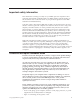
Locating the connectors on the rear of your computer The following illustration shows the locations of the connectors on the rear of the computer.
Connector Description Mouse connector Used to attach a mouse, trackball, or other pointing device that uses a standard mouse connector. Parallel connector Used to attach a parallel printer, parallel scanner, or other devices that use a 25-pin parallel connector. USB connectors Used to attach a device that requires a Universal Serial Bus (USB) connection, such as a USB scanner or USB printer.
Removing the cover Important: Read “Important safety information” on page v and “Handling static-sensitive devices” on page 27 before removing the cover. To remove the cover: 1. Shut down your operating system, remove any media (diskettes, CDs, or tapes) from the drives, and turn off all attached devices and the computer. 2. Unplug all power cords from electrical outlets. 3. Disconnect all cables attached to the computer.
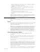
Locating components The following illustration will help you locate the various components in your computer. 1 CD drive or DVD drive 2 USB connector 3 USB connector 4 Optional drive bay 5 Hard disk drive 6 Diskette drive 7 DIMMs 8 Microprocessor and heat sink 9 AGP slot 10 Battery 11 PCI slots Identifying parts on the system board The system board (sometimes called the planar or motherboard) is the main circuit board in your computer.
The following illustration shows the locations of parts on the system board.
To install a DIMM: 1. Remove the cover. See “Removing the cover” on page 31. 2. You might have to remove an adapter to gain access to the DIMM slots. See “Installing adapters” on page 34. 3. Locate the DIMM connectors. See “Identifying parts on the system board” on page 32. 4. Open the retaining clips. 5. Make sure the notches in the DIMM align with the tabs on the connector. Push or insert the DIMM straight down into the connector until the retaining clips close.
To install an adapter: 1. Remove the cover. See “Removing the cover” on page 31. 2. Remove the adapter-slot-cover latch and the slot cover for the appropriate expansion slot. 3. Remove the adapter from its static-protective package. 4. Install the adapter into the appropriate slot on the system board. 5. Install the adapter-slot-cover latch. What to do next: v To work with another option, go to the appropriate section.
Installing internal drives This section provides information and instructions for installing and removing internal drives. Internal drives are devices that your computer uses to read and store data. You can add drives to your computer to increase storage capacity and to enable your computer to read other types of media.
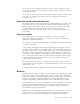
The following illustration shows the locations of the drive bays. The following list describes some of the drives that you can install in each bay and their height requirements: 1 Bay 1 - Maximum height: 43.0 mm (1.7 in.) 2 Bay 2 - Maximum height: 43.0 mm (1.7 in.) 3 Bay 3 - Maximum height: 25.8 mm (1.0 in.) 4 Bay 4 - Maximum height: 25.8 mm (1.0 in.) CD drive or DVD drive (preinstalled in some models) 5.25-inch hard disk drive 5.25-inch hard disk drive 3.
4. Remove the metal shield from the drive bay by inserting a flat-blade screwdriver into one of the slots and gently prying it loose. 5. Pivot the drive-bay latch handle toward the front of the computer and then pivot the drive-bay cage upward, as shown, until it is latched in the upright position. 6. Make sure the drive that you are installing is set correctly as either a master or a slave device. Note: A serial ATA hard disk drive does not need to be set as either a master or a slave device.
7. Install the drive into the bay. Align the screw holes and insert the two screws. 8. Pivot the drive-bay cage back into place. 9. A hard disk drive requires two cables; a power cable that connects to the power supply and a signal cable that connects to the system board. v A parallel ATA hard disk drive requires a four-wire power cable. v A serial ATA hard disk drive requires a five-wire power cable. The steps to connect a drive are different depending on the type of drive you are connecting.
4. Your computer has extra power connectors for additional drives. Connect a power connector to the drive. 5. If you have a CD-ROM audio cable, connect it to the drive and to the system board. See “Identifying parts on the system board” on page 32. Connecting an additional CD drive, DVD drive, or parallel ATA hard disk drive 1. Locate the PATA secondary IDE connector on the system board and the three-connector signal cable. See “Identifying parts on the system board” on page 32. 2.
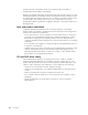
Identifying security locks The following illustration shows the locations of the security features on the rear of the computer. 1 Rope clip 2 Integrated cable lock Rope clip Using a 3/16-inch or 5-mm rope clip (sometimes referred to as a U-bolt), a steel security cable, and a padlock can secure your computer to a desk, table, or other non-permanent fixture. For computers designed to accommodate the rope clip, knockouts at the rear of the chassis are provided. To 1. 2. 3.
5. Thread the cable through the rope clip and around an object that is not a part of or permanently secured to the building structure or foundation, and from which it cannot be removed; then fasten the cable ends together with a lock.
Integrated cable lock With an integrated cable lock (sometimes referred to as a Kensington lock), you can secure your computer to a desk, table, or other non-permanent fixture. The cable lock attaches to a security slot at the rear of your computer and is operated with a key. This is the same type of lock used with many laptop computers. You can order a cable lock directly from IBM. Go to http://www.pc.ibm.com/support and search on Kensington.
Refer to “Lithium battery notice” on page x for information about replacing and disposing of the battery. To change the battery: 1. Turn off the computer and all attached devices. 2. Remove the cover. See “Removing the cover” on page 31. 3. Locate the battery. See “Identifying parts on the system board” on page 32. 4. If necessary, remove any adapters that impede access to the battery. See “Installing adapters” on page 34 for more information. 5. Remove the old battery. 6. Install the new battery. 7.
5. Move the jumper from the standard position (pins 1 and 2) to the maintenance or configure position (pins 2 and 3). 6. Replace the cover and connect the power cord. See “Replacing the cover and connecting the cables.” 7. Restart the computer, leave it on for approximately 10 seconds. Turn off the computer by holding the power switch for approximately 5 seconds. The computer will turn off. 8. Repeat steps 2 through 4 on page 44. 9. Move the jumper back to the standard (pins 1 and 2). 10.
46 User Guide
Chapter 3. Types 8196 and 8197 This chapter provides an introduction to the features and options that are available for your computer. You can expand the capabilities of your computer by adding memory, adapters, or drives. When installing an option, use these instructions along with the instructions that come with the option. Important Before you install or remove any option, read “Important safety information” on page v. These precautions and guidelines will help you work safely.
Internal drives v 3.5-inch, 1.
v Advanced Power Management support v Advanced Configuration and Power Interface (ACPI) support Security features v User and administrator passwords v Support for the addition of a rope clip and lockable cable v Support for the addition of an integrated cable lock v Support for a padlock on the chassis v v v v v v Startup sequence control Startup without diskette drive, keyboard, or mouse Unattended start mode Diskette and hard disk I/O control Serial and parallel port I/O control Security profile by devic
Specifications This section lists the physical specifications for your computer. Dimensions Height: 398 mm (15.67 in.) Width: 180 mm (7.08 in.) Minimum configuration: 257 Btu/hr (75 watts) Depth: 402 mm (15.82 in.) Maximum configuration: 785 Btu/hr (230 watts) Airflow Weight Minimum configuration as shipped: 7.6 kg (16.8 lb) Maximum configuration: 9.
Available options The following are some available options: v External options – Parallel port devices, such as printers and external drives – Serial port devices, such as external modems and digital cameras – Audio devices, such as external speakers for the sound system – USB devices, such as printers, joysticks, and scanners – Security device, such as a rope clip – Monitors v Internal options – System memory, called dual inline memory modules (DIMMs) – Peripheral component interconnect (PCI) adapters – Ac
v Prevent others from touching components. v When you install a new option, touch the static-protective package containing the option to a metal expansion-slot cover or other unpainted metal surface on the computer for at least two seconds. This reduces static electricity in the package and your body. v When possible, remove the option and install it directly in the computer without setting the option down.
Locating the connectors on the front of your computer The following illustration shows the locations of the USB connectors on the front of the computer. 1 USB connector 2 USB connector Chapter 3.
Locating the connectors on the rear of your computer The following illustration shows the locations of the connectors on the rear of the computer.
Connector Description Mouse connector Used to attach a mouse, trackball, or other pointing device that uses a standard mouse connector. Keyboard connector Used to attach a keyboard that uses a standard keyboard connector. Serial connector Used to attach an external modem, serial printer, or other devices that use a 9-pin serial connector. Parallel connector Used to attach a parallel printer, parallel scanner, or other devices that use a 25-pin parallel connector.
Removing the cover Important Read “Important safety information” on page v and “Handling static-sensitive devices” on page 51 before removing the cover. To remove the cover: 1. Shut down your operating system, remove any media (diskettes, CDs, or tapes) from the drives, and turn off all attached devices and the computer. 2. Unplug all power cords from electrical outlets. 3. Disconnect all cables attached to the computer.
Locating components The following illustration will help you locate the various components in your computer. 1 Microprocessor and heat sink 2 DIMMs 3 AGP slot 4 PCI slots 5 PCI adapter 6 Power supply Identifying parts on the system board The system board (sometimes called the planar or motherboard) is the main circuit board in your computer. It provides basic computer functions and supports a variety of devices that are IBM-installed or that you can install later. Chapter 3.
The following illustration shows the locations of parts on the system board.
To install a DIMM: 1. Remove the cover. See “Removing the cover” on page 56. 2. You might have to remove an adapter to gain access to the DIMM slots. See “Installing adapters” on page 60. 3. Locate the DIMM connectors. See “Identifying parts on the system board” on page 57. 4. Open the retaining clips. 5. Make sure the notches in the DIMM align with the tabs on the connector. Push or insert the DIMM straight down into the connector until the retaining clips close.
Installing adapters This section provides information and instructions for installing and removing adapters. Your computer has three expansion slots for PCI adapters. You can install an adapter up to 228 mm (9 inches) long. To install an adapter: 1. Remove the cover. See “Removing the cover” on page 56. 2. Remove the adapter slot cover for the appropriate expansion slot. 3. Remove the adapter from its static-protective package. 4. Install the adapter into the appropriate slot on the system board.
5. Secure the adapter with the screw as shown. What to do next v To work with another option, go to the appropriate section. v To complete the installation, go to “Replacing the cover and connecting the cables” on page 70. Installing internal drives This section provides information and instructions for installing and removing internal drives. Internal drives are devices that your computer uses to read and store data.
Drive specifications Your computer comes with the following IBM-installed drives: v A CD drive or DVD drive in bay 1 v A 3.5-inch diskette disk drive in bay 3 v A 3.5-inch hard drive in bay 4 Any bay that does not have a drive installed has a static shield and bay panel installed. The following illustration shows the locations of the drive bays. The following table describes some of the drives you can install in each bay and their height requirements. 1 Bay 1 - Maximum height: 43.0 mm (1.7 in.
3. Remove the bay panel from the drive bay by inserting a flat-blade screwdriver at the end and gently prying it loose. 4. Remove the metal shield from the drive bay by inserting a flat-blade screwdriver into one of the slots and gently prying it loose. 5. Make sure the drive that you are installing is set correctly as either a master or a slave device. Note: A serial ATA hard disk drive does not need to be set as either a master or a slave device.
6. Install the drive into the bay. Align the screw holes and install two screws to secure the drive. 7. A hard disk drive requires two cables; a power cable that connects to the power supply and a signal cable that connects to the system board. v A parallel ATA hard disk drive requires a four-wire power cable. v A serial ATA hard disk drive requires a five-wire power cable. The steps to connect a drive are different depending on the type of drive you are connecting.
3. Connect one end of the signal cable to the drive and the other to the PATA secondary IDE connector on the system board. To reduce electronic noise, use the connectors at the end of the cable only. 4. Your computer has extra power connectors for additional drives. Connect a power connector to the drive. 5. If you have a CD-ROM audio cable, connect it to the drive and to the system board. See “Identifying parts on the system board” on page 57.
Identifying security locks The following illustration shows the locations of the security features on the rear of the computer. 1 Rope clip 2 Integrated cable lock 3 Padlock loop Rope clip Using a 3/16-inch or 5-mm rope clip (sometimes referred to as a U-bolt), a steel security cable, and a padlock can secure your computer to a desk, table, or other non-permanent fixture. For computers designed to accommodate the rope clip, knockouts at the rear of the chassis are provided. To 1. 2. 3.
5. Thread the cable through the rope clip and around an object that is not a part of or permanently secured to the building structure or foundation, and from which it cannot be removed; then fasten the cable ends together with a lock. ® Chapter 3.
Integrated cable lock With an integrated cable lock (sometimes referred to as a Kensington lock), you can secure your computer to a desk, table, or other non-permanent fixture. The cable lock attaches to a security slot at the rear of your computer and is operated with a key. This is the same type of lock used with many laptop computers. You can order a cable lock directly from IBM. Go to http://www.pc.ibm.com/support and search on Kensington.
Refer to “Lithium battery notice” on page x for information about replacing and disposing of the battery. To change the battery: 1. Turn off the computer and all attached devices. 2. Unplug the power cord and remove the cover. See “Removing the cover” on page 56. 3. Locate the battery. See “Identifying parts on the system board” on page 57. 4. If necessary, remove any adapters that impede access to the battery. See “Installing adapters” on page 60 for more information. 5. Remove the old battery. 6.
To erase a forgotten password: 1. Turn off the computer and all attached devices. 2. Remove the cover. See “Removing the cover” on page 56. 3. Locate the Clear CMOS/Recovery jumper on the system board. See “Identifying parts on the system board” on page 57. 4. If necessary, see “Installing adapters” on page 60 to remove any adapters that impede access to the Clear CMOS/Recovery jumper. 5. Move the jumper from the standard position (pins 1 and 2) to the maintenance or configure position (pins 2 and 3). 6.
3. Position the cover on the chassis so that the guides on the top and bottom of the cover engage the chassis and push the cover to the closed position. Insert the screws that secure the cover. 4. Reconnect the external cables and power cords to the computer. See “Installing external options” on page 52. 5. To update the configuration, see Chapter 5, “Using the IBM Setup Utility program,” on page 99. Chapter 3.
72 User Guide
Chapter 4. Types 8189, 8190, 8194, 8195, 8415, 8432, and 8433 This chapter provides an introduction to the features and options that are available for your computer. You can expand the capabilities of your computer by adding memory, adapters, or drives. When installing an option, use these instructions along with the instructions that come with the option. Important Before you install or remove any option, read “Important safety information” on page v.
v 512 KB flash memory for system programs Internal drives v 3.5-inch, 1.
Expansion v Five drive bays v Three 32-bit peripheral component interconnect (PCI) adapter slots v One accelerated graphics port (AGP) expansion slot Power v 230 W power supply with manual voltage selection switch v Automatic 50/60 Hz input frequency switching v Advanced Power Management support v Advanced Configuration and Power Interface (ACPI) support Security features v User and administrator passwords v v v v v v v v Support for the addition of a rope clip and lockable cable Support for the addition o
Specifications This section lists the physical specifications for your computer. Dimensions Height: 413 mm (16.25 in.) Width: 191 mm (7.5 in.) Minimum configuration: 257 Btu/hr (75 watts) Depth: 406 mm (16 in.) Maximum configuration: 785 Btu/hr (230 watts) Airflow Weight Minimum configuration as shipped: 9.1 kg (20 lb) Maximum configuration: 11.4 kg (25.
Available options The following are some available options: v External options – Parallel port devices, such as printers and external drives – Serial port devices, such as external modems and digital cameras – Audio devices, such as external speakers for the sound system – USB devices, such as printers, joysticks, and scanners – Security device, such as a rope clip – Monitors – IEEE 1394 devices (requires an IEEE 1394 adapter) v Internal options – System memory, called dual inline memory modules (DIMMs) – P
v Always handle components carefully. Handle adapters and memory modules by the edges. Never touch any exposed circuitry. v Prevent others from touching components. v When you install a new option, touch the static-protective package containing the option to a metal expansion-slot cover or other unpainted metal surface on the computer for at least two seconds. This reduces static electricity in the package and your body.
Locating the connectors on the front of your computer The following illustration shows the locations of the connectors on the front of the computer. Note: Not all computer models will have the following connectors. 1 IEEE 1394 connector 2 Microphone connector 3 Headphone connector 4 USB connector 5 USB connector Chapter 4.
Locating the connectors on the rear of your computer The following illustration shows the locations of the connectors on the rear of the computer.
Connector Description Mouse connector Used to attach a mouse, trackball, or other pointing device that uses a standard mouse connector. Keyboard connector Used to attach a keyboard that uses a standard keyboard connector. Serial connector Used to attach an external modem, serial printer, or other devices that use a 9-pin serial connector. Parallel connector Used to attach a parallel printer, parallel scanner, or other devices that use a 25-pin parallel connector.
Removing the cover Important Read “Important safety information” on page v and “Handling static-sensitive devices” on page 77 before removing the cover. To remove the cover: 1. Shut down your operating system, remove any media (diskettes, CDs, or tapes) from the drives, and turn off all attached devices and the computer. 2. Unplug all power cords from electrical outlets. 3. Disconnect all cables attached to the computer.
Locating components The following illustration will help you locate the various components in your computer. 1 Microprocessor and heat sink 2 DIMMs 3 AGP slot 4 PCI adapter 5 Power supply Identifying parts on the system board The system board (sometimes called the planar or motherboard) is the main circuit board in your computer. It provides basic computer functions and supports a variety of devices that are IBM-installed or that you can install later. Chapter 4.
The following illustration shows the locations of parts on the system board.
To install a DIMM: 1. Remove the cover. See “Removing the cover” on page 82. 2. You might have to remove an adapter to gain access to the DIMM slots. See “Installing adapters.” 3. Locate the DIMM connectors. See “Identifying parts on the system board” on page 83. 4. Open the retaining clips. 5. Make sure the notches in the DIMM align with the tabs on the connector. Push or insert the DIMM straight down into the connector until the retaining clips close.
2. Remove the adapter-slot-cover latch and the slot cover for the appropriate expansion slot. 3. Remove the adapter from its static-protective package. 4. Install the adapter into the appropriate slot on the system board. 5. Install the adapter-slot-cover latch. What to do next v To work with another option, go to the appropriate section. v To complete the installation, go to “Replacing the cover and connecting the cables” on page 96.
Installing internal drives This section provides information and instructions for installing and removing internal drives. Internal drives are devices that your computer uses to read and store data. You can add drives to your computer to increase storage capacity and to enable your computer to read other types of media.
The following illustration shows the locations of the drive bays. The following list describes some of the drives you can install in each bay and their height requirements: 1 Bay 1 - Maximum height: 43.0 mm (1.7 in.) 2 Bay 2 - Maximum height: 43.0 mm (1.7 in.) 3 Bay 3 - Maximum height: 25.8 mm (1.0 in.) 4 Bay 4 - Maximum height: 25.8 mm (1.0 in.) 5 Bay 5 - Maximum height: 25.8 mm (1.0 in.) CD drive or DVD drive (preinstalled in some models) 5.25-inch hard disk drive 5.25-inch hard disk drive 3.
4. Remove the metal shield from the drive bay by inserting a flat-blade screwdriver into one of the slots and gently prying it loose. 5. Make sure the drive that you are installing is set correctly as either a master or a slave device. Note: A serial ATA hard disk drive does not need to be set as either a master or a slave device. v If it is the first CD drive or DVD drive, set it as a master device. v If it is an additional CD drive or DVD drive, set it as a slave device.
7. Install the drive into the bay and lock it into position. Note: Some drives might require screws to secure the drive into the bay. If this is the case, align the screw holes, and insert the screws to secure the drive. 8. A hard disk drive requires two cables; a power cable that connects to the power supply and a signal cable that connects to the system board. v A parallel ATA hard disk drive requires a four-wire power cable. v A serial ATA hard disk drive requires a five-wire power cable.
2. Locate the PATA secondary IDE connector on the system board. See “Identifying parts on the system board” on page 83. 3. Connect one end of the signal cable to the drive and the other to the PATA secondary IDE connector on the system board. To reduce electronic noise, use the connectors at the end of the cable only. 4. Your computer has extra power connectors for additional drives. Connect a power connector to the drive. 5. If you have a CD-ROM audio cable, connect it to the drive and to the system board.
Identifying security locks The following illustration shows the locations of the security features on the rear of the computer. 1 Rope clip 2 Integrated cable lock Rope clip Using a 3/16-inch or 5-mm rope clip (sometimes referred to as a U-bolt), a steel security cable, and a padlock can secure your computer to a desk, table, or other non-permanent fixture. For computers designed to accommodate the rope clip, knockouts at the rear of the chassis are provided. To install a rope clip: 1.
5. Thread the cable through the rope clip and around an object that is not a part of or permanently secured to the building structure or foundation, and from which it cannot be removed; then fasten the cable ends together with a lock. ® Chapter 4.
Integrated cable lock With an integrated cable lock (sometimes referred to as a Kensington lock), you can secure your computer to a desk, table, or other non-permanent fixture. The cable lock attaches to a security slot at the rear of your computer and is operated with a key. This is the same type of lock used with many laptop computers. You can order a cable lock directly from IBM. Go to http://www.pc.ibm.com/support and search on Kensington.
configuration information (including passwords) are lost. An error message is displayed when you turn on the computer. Refer to “Lithium battery notice” on page x for information about replacing and disposing of the battery. To change the battery: 1. Turn off the computer and all attached devices. 2. Remove the cover. See “Removing the cover” on page 82. 3. Locate the battery. See “Identifying parts on the system board” on page 83. 4. If necessary, remove any adapters that impede access to the battery.
3. Locate the Clear CMOS/Recovery jumper on the system board. See “Identifying parts on the system board” on page 83. 4. If necessary, see “Installing adapters” on page 85 to remove any adapters that impede access to the Clear CMOS/Recovery jumper. 5. Move the jumper from the standard position (pins 1 and 2) to the maintenance or configure position (pins 2 and 3). 6. Replace the cover and connect the power cord. See “Replacing the cover and connecting the cables.” 7.
5. To update the configuration, see Chapter 5, “Using the IBM Setup Utility program,” on page 99. Chapter 4.
98 User Guide
Chapter 5. Using the IBM Setup Utility program The IBM Setup Utility program is stored in the electrically erasable programmable read-only memory (EEPROM) of your computer. The IBM Setup Utility program is used to view and change the configuration settings of your computer, regardless of which operating system you are using. However, the operating-system settings might override any similar settings in the IBM Setup Utility program.
User password The user password feature deters unauthorized persons from gaining access to your computer. Administrator password Setting an administrator password deters unauthorized persons from changing configuration settings. If you are responsible for maintaining the settings of several computers, you might want to set an administrator password. After you set an administrator password, a password prompt is displayed each time you try to access the IBM Setup Utility program.
Using IDE Drives Setup In addition to listing the different IDE devices, there are options for configuring the serial and parallel IDE controllers. Parallel ATA Serial ATA Native Mode Operation This setting allows the user to disable one or both of the parallel IDE controllers. This setting allows the user to disable the serial ATA controllers. This setting is only available when the serial ATA controller is enabled.
1. Start the IBM Setup Utility program (see “Starting the IBM Setup Utility program” on page 99). 2. Select Startup. 3. Select Startup Sequence. See the information displayed on the right side of the screen. 4. Select the sequence of devices for the Primary Startup Sequence, the Automatic Startup Sequence, and the Error Startup Sequence. 5. Select Exit from the IBM Setup Utility menu and then Save Settings.
Appendix A. Updating system programs This appendix contains information about updating system programs and how to recover from a POST/BIOS update failure. System programs System programs are the basic layer of software that is built into your computer. They include the power-on self-test (POST), the basic input/output system (BIOS) code, and the IBM Setup Utility program. POST is a set of tests and procedures that is performed each time you turn on your computer.
6. Scroll down and look for a .txt file that has instructions for Flash BIOS update from the operating system. Click the .txt file. 7. Print these instructions. This is very important since they are not on the screen after the download begins. 8. From your browser, Click Back to return to the list of files. Carefully follow the printed instructions to download, extract, and install the update.
Appendix B. Cleaning the mouse This appendix provides instructions on how to clean your mouse. The procedure will be different depending on which type of mouse you have. Cleaning an optical mouse If you experience some problems with your optical mouse, check the following: 1. Turn the mouse over and look carefully at the lens area. a. If there is a smudge on the lens, gently clean the area with a plain cotton swab or plain q-tip. b.
3. Place your hand over the retainer ring and ball 2 , and then turn the mouse over, top side up, so that the retainer ring and ball fall out into your hand. 4. Wash the ball in warm, soapy water then dry it with a clean cloth. Blow air carefully into the ball cage 4 to dislodge dust and lint. 5. Look for a build up of dirt on the plastic rollers 3 inside the ball cage. This build up usually appears as a stripe running across the middle of the rollers. 6.
Appendix C. Manual modem commands The following section lists commands for manually programming your modem. Commands are accepted by the modem while it is in Command Mode. Your modem is automatically in Command Mode until you dial a number and establish a connection. Commands may be sent to your modem from a PC running communication software or any other terminal devices. All commands sent to the modem must begin with AT and end with ENTER.
Command Function H1 Force modem off-hook (make busy) Note: H1 command is not supported for Italy I_ L_ M_ I0 Display product-identification code I1 Factory ROM checksum test I2 Internal memory test I3 Firmware ID I4 Reserved ID L0 Low speaker volume L1 Low speaker volume L2 Medium speaker volume L3 High speaker volume M0 Internal speaker off M1 Internal speaker on until carrier detected M2 Internal speaker always on M3 Internal speaker on until carrier detected and off while d
Extended AT commands Command Function &C0 Force Carrier Detect Signal High (ON) &C1 Turn on CD when remote carrier is present &D0 Modem ignores the DTR signal &D1 Modem returns to Command Mode after DTR toggle &D2 Modem hangs up, returns to the Command Mode after DTR toggle &D3 Resets modem after DTR toggle &F_ &F Recall factory default configuration &G_ &G0 Guard tone disabled &G1 Guard tone disabled &G2 1800 Hz guard tone &K0 Disable flow control &K3 Enable RTS/CTS hardware flow
Command Function &W_ %E_ &V1 Display Last Connection Statistics &W0 Stores the active profile as Profile 0 &W1 Stores the active profile as Profile 1 %E0 Disable auto-retrain %E1 Enable auto-retrain +MS? Displays the current Select Modulation settings +MS=? Displays a list of supported Select Modulation options +MS=a,b,c,e,f Select modulation where: a=0, 1, 2, 3, 9, 10, 11, 12, 56, 64, 69; b=0-1; c=300-56000; d=30056000; e=0-1; and f=0-1. A, b, c, d, e, f default=12, 1, 300, 56000, 0, 0.
Fax Class 1 commands +FAE=n Data/Fax Auto Answer +FCLASS=n Service Class +FRH=n Receive data with HDLC framing +FRM=n Receive data +FRS=n Receive silence +FTH=n Transmit data with HDLC framing +FTM=n Transmit data +FTS=n Stop transmission and wait Fax Class 2 commands +FCLASS=n Services class. +FAA=n Adaptive answer. +FAXERR Fax error value. +FBOR Phase C data bit order. +FBUF? Buffer size (read only). +FCFR Indicate confirmation to receive. +FCLASS= Service class.
+FPHCTO Phase C time out. +FPOLL Indicates polling request. +FPTS: Page transfer status. +FPTS= Page transfer status. +FREV? Identify revision. +FSPT Enable polling. +FTSI: Report the transmit station ID.
Attention Switzerland User: If your Swisscom phone line does not have Taxsignal switched OFF, modem function may be impaired. The impairment may be resolved by a filter with the following specifications: Telekom PTT SCR-BE Taximpulssperrfilter-12kHz PTT Art. 444.112.7 Bakom 93.0291.Z.N Appendix C.
114 User Guide
Appendix D. Customer replaceable unit (CRU) parts list For your computer, the following parts are designated customer replaceable unit (CRU) parts. Refer to the warranty section of your Quick Reference for more information. CRU parts list All option and adapter cards All bezels All keyboards All mice All external speakers All memory All keylocks All cables All hard disk drives, optical drives, and diskette drives Internal speaker assembly RFID antenna Speaker power supply EMC shield 5.
116 User Guide
Appendix E. Notices IBM may not offer the products, services, or features discussed in this document in all countries. Consult your local IBM representative for information on the products and services currently available in your area. Any reference to an IBM product, program, or service is not intended to state or imply that only that IBM product, program, or service may be used.
Television output notice The following notice applies to models that have the factory-installed television-output feature. This product incorporates copyright protection technology that is protected by method claims of certain U.S. patents and other intellectual property rights owned by Macrovision Corporation and other rights owners.
Index A adapters accelerated graphics port (AGP) 5, 27, 51, 77 installing Types 8128, 8187, 8188, 8193, 8414, and 8431 35 Types 8185, 8186, 8192, 8413, and 8430 13 Types 8189, 8190, 8194, 8195, 8415, 8432, and 8433 85 Types 8196 and 8197 60 peripheral component interconnect (PCI) 5, 27, 51, 77 slots 12, 34, 60, 85 audio line in connector 8, 30, 55, 81 audio line out connector 8, 30, 55, 81 audio, subsystem 2, 24, 48, 74 C cables, connecting 21, 45, 70, 96 changing the battery Types 8128, 8187, 8188, 8193,
modem Basic AT commands 107 Extended AT commands 109 Fax Class 1 commands 111 Fax Class 2 commands 111 MNP/V.42/V.42bis/V.
Part Number: 13R9196 Printed in USA (1P) P/N: 13R9196