I BM ® IBM Flex System Enterprise Chassis IBM Redbooks Product Guide IBM Flex System™, a new category of computing and the next generation of Smarter Computing, is anchored by the IBM Flex System Enterprise Chassis. This platform offers intelligent workload deployment and management for maximum business agility. This chassis delivers high-speed performance complete with integrated servers, storage, and networking for multiple chassis management in data center compute environments.
Key features The IBM Flex System Enterprise Chassis is a simple, integrated infrastructure platform that supports a mix of compute, storage, and networking resources to meet the demands of your applications. The solution is easily scalable with the addition of another chassis with the required nodes. With the IBM Flex System Manager, multiple chassis can be monitored from a single screen. The 14 node, 10U chassis delivers high-speed performance complete with integrated servers, storage, and networking.
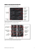
Locations of key components and connectors Figure 2 shows the front of the Enterprise Chassis. Figure 2. Front of the IBM Flex System Enterprise Chassis Figure 3 shows the rear of the Enterprise Chassis. Figure 3.
Standard specifications The following table lists the standard specifications. Table 1. Standard specifications Components Specification Model System x® ordering sales channel: 8721-A1x Power Systems™ sales channel: 7893-92X Form factor 10U rack-mounted unit. Maximum number of compute nodes supported 14 half-wide (single bay), seven full-wide (two bays), or three double-height full-wide (four bays). Mixing is supported. Chassis per 42U rack Four. Nodes per 42U rack 56 half-wide, or 28 full-wide.
The IBM Flex System Enterprise Chassis model 8721-A1x ships with the following items: One Chassis Management Module Two 2500 W power supplies Four 80 mm Fan Modules Two 40 mm Fan Modules Four Power Supply Fillers One Console Breakout Cable Two C19 to C20 two-meter power cables One Rack Mount Kit Supported compute nodes The following table lists the compute nodes that are supported in the IBM Flex System Enterprise Chassis. The table also lists the maximum number installable. Table 2.
Supported I/O modules The IBM Flex System Enterprise Chassis has four high-speed switch bays that are capable of supporting a variety of I/O architectures. The switches are installed in switch bays in the rear of the IBM Flex System Enterprise Chassis as shown in the following figure. Switches are normally installed in pairs (bays 1 & 2, and bays 3 & 4), because I/O adapter cards installed in the compute nodes route to two switch bays for performance and redundancy. Figure 4.
The following table lists the switches that are available for the chassis. Table 3.
I/O architecture Each half-wide compute node (such as the IBM Flex System x240 Compute Node) has two adapter slots, and each full-wide compute node (such as the IBM Flex System x460 Compute Node) has four adapter slots. The adapter slots in each compute node route through the chassis midplane to the switch bays. The architecture supports up to eight ports per adapter although currently only two-port and four-port adapters are available.
A four-port adapter doubles the connections between each adapter and switch pair (for example, a four-port adapter in A1 in each compute node routes two connections to switch 1 and two connections to switch 2). The following figure shows how four-port adapters are connected to switches that are installed in the chassis. Figure 7.
The following table shows the connections between adapter slots in the compute nodes to the switch bays in the chassis. Table 4.
Chassis Management Module The Chassis Management Module (CMM) provides single-chassis management. The CMM is used to communicate with the management controller in each compute node (IMMv2 in Intel processor-based compute nodes and FSP in POWER7® processor-based compute nodes) to provide system monitoring, event recording and alerts, and to manage the chassis, its devices, and the compute nodes. The chassis supports up to two CMMs.
The CMM has the following connectors: USB connection. This connection can be used for insertion of a USB media key for tasks, such as firmware updates. 10/100/1000 Mbps RJ45 Ethernet connection to connect to a management network. The CMM can be managed via this Ethernet port. Serial port (mini-USB) for local command-line interface (CLI) management. Use serial cable 90Y9338 for connectivity.
The CMM has a high-security policy that is enabled by default, which means that the following policies are enabled by default: Strong password policies with automatic validation and verification checks Required update of the default passwords after the initial setup Only secure communication protocols, such as SSH and SSL. Unencrypted protocols, such as HTTP, Telnet, and SNMPv1, are disabled.
The IBM Flex System Manager offers these main features: Monitoring and problem determination: A real-time multichassis view of hardware components with overlays for additional information Automatic detection of issues in your environment through an event setup that triggers alerts and actions Identification of changes that might affect availability Server resource utilization by virtual machine or across a rack of systems Hardware management: Automated discovery of physical and v
Additional features: Resource-oriented chassis map provides instant graphical view of chassis resources, including nodes and I/O modules Remote console, including remote keyboard, video, mouse (KVM) session, remotely mounted optical and USB media, and remote power control Hardware detection and inventory creation Firmware compliance and updates Automatic detection of hardware failures and alerting.
Both power supplies are 80 PLUS Platinum-certified. The 2500W modules are 2500 Watts output rated at 200VAC to 208VAC (nominal), and 2750W at 220VAC to 240VAC (nominal). The power supply has an oversubscription rating of up to 3538 Watts output at 200VAC. The power supply operating range is 200-240 VAC. The power supplies also contain two dual independently powered 40mm cooling fan modules that are powered not from the power supply itself, but from the chassis midplane.
The chassis supports up to six power supplies. The following table shows the required 2500W power supplies, depending on the number of compute nodes installed and the desired level of redundancy. Because the chassis has one power domain, it does not matter where the power supplies are installed. However, it is advised that you install the power supplies starting from the bottom power supply bays.
Each power supply option includes a power cable. Each power supply standard with the chassis includes a power cable. It is a 2-meter (6.5 ft) 16A/100-250V, C19 to IEC 320-C20 Rack Power Cable, feature code 6292. Other supported line cords including three-way split line cords, are listed in the following table. Table 8. Supported line cords Description Part number System x Feature code 4.3m, 16A/208V, C19 to NEMA L6-20P (US) Line Cord 40K9772 6275 2.
Fan modules The Enterprise Chassis supports up to a total of ten hot-swap fan modules: two 40 mm (1.57 in) fan modules and eight 80 mm (3.14 in) fan modules. The two 40 mm fan modules distribute airflow to the I/O modules and chassis management modules. Both of these fan modules ship with the chassis. The 80 mm fan modules distribute airflow to the compute nodes through the chassis from front to rear.
Figure 13. Fan module locations and cooling zones The 40 mm fan modules are always required. Additional 80 mm fan modules are required as listed in the following table. Table 10.
Supported environment The IBM Flex System Enterprise Chassis complies with ASHRAE Class A3 specifications. The following environment is the supported operating environment.
Warranty options The IBM Flex System Enterprise Chassis has a three-year on-site warranty with 9x5 next-business-day terms. IBM offers the warranty service upgrades through IBM ServicePac®, discussed in this section. The IBM ServicePac is a series of prepackaged warranty maintenance upgrades and post-warranty maintenance agreements with a well-defined scope of services, including service hours, response time, term of service, and service agreement terms and conditions.
Regulatory compliance The server conforms to the following standards: ASHRAE Class A3 FCC - Verified to comply with Part 15 of the FCC Rules Class A Canada ICES-004, issue 3 Class A UL/IEC 60950-1 CSA C22.2 No. 60950-1 NOM-019 Argentina IEC 60950-1 Japan VCCI, Class A IEC 60950-1 (CB Certificate and CB Test Report) China CCC (GB4943); (GB9254, Class A); (GB17625.
External disk storage systems The following options are available for attaching external storage systems to Enterprise Chassis: IBM Storwize® V7000 IBM XIV® Storage System series IBM System Storage® DS8000® series IBM System Storage DS5000 series IBM System Storage DS3000 series IBM System Storage N series The IBM Storwize V7000 is an ideal storage offering for IBM Flex System configurations.
Top-of-rack Ethernet switches For enterprise-class installations with multiple IBM Flex System Enterprise Chassis configurations, a top-of-rack Ethernet switch from IBM System Networking provides the necessary level of networking between racks of systems and the rest of your production network. The following table lists the available top-of-rack switches. Table 12.
Power distribution units Power planning for an IBM Flex System Enterprise Chassis is essential. The Enterprise Chassis has a maximum of six power supplies installed. So, careful consideration must be given to providing the best power-optimized source. Both N+N and N+1 configurations are supported for maximum flexibility in power redundancy. Each power supply in the chassis has a 16A C20 three-pin socket and can be fed by a C19 power cable, from a suitable supply.
Uninterruptible power supply units The IBM Flex System Enterprise Chassis supports attachments to the uninterruptible power supply units listed in the following table. Table 14.
Rack options The server supports the rack console switches and monitor kits listed in the following table. Table 16.
IBM Global Financing IBM Global Financing can help you obtain the IT solution you need while preserving funding for other strategic investments and optimizing cash flow. Our Fair Market Value (FMV) lease helps ensure that you have the latest IBM technology and with our mid-lease upgrade capability, you can increase the capacity of the system with little to no change in monthly payments. At the end of the lease, take advantage of our flexible end-of-lease options to fit your changing business needs.
Related publications and links For more information, see the following resources: IBM Flex System product page http://ibm.com/systems/flex IBM US Product Announcement for the IBM Flex System Enterprise Chassis http://ibm.com/common/ssi/cgi-bin/ssialias?infotype=dd&subtype=ca&&htmlfid=897/ENUS112-053 IBM Flex System Information Center http://publib.boulder.ibm.com/infocenter/flexsys/information/index.jsp IBM Flex System Enterprise Chassis Installation and Service Guide http://publib.boulder.
Notices This information was developed for products and services offered in the U.S.A. IBM may not offer the products, services, or features discussed in this document in other countries. Consult your local IBM representative for information on the products and services currently available in your area. Any reference to an IBM product, program, or service is not intended to state or imply that only that IBM product, program, or service may be used.
This document was created or updated on October 30, 2012. Send us your comments in one of the following ways: Use the online Contact us review form found at: i bm. com/ r edbooks Send your comments in an e-mail to: r edbook@ us. i bm. com Mail your comments to: IBM Corporation, International Technical Support Organization Dept. HYTD Mail Station P099 2455 South Road Poughkeepsie, NY 12601-5400 U.S.A. This document is available online at ht t p: / / www. i bm.