
Datasheet


IBM Flex System Enterprise Chassis 10
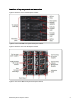
The following table shows the connections between adapter slots in the compute nodes to the switch bays
in the chassis.
Table 4. Adapter to I/O bay correspondence
I/O adapter slot
in the server
Port on the adapter Corresponding I/O module bay
in the chassis
Port 1 Module bay 1
Port 2 Module bay 2
Port 3 (for 4-port cards)* Module bay 1
Slot 1
Port 4 (for 4-port cards)* Module bay 2
Port 1 Module bay 3
Port 2 Module bay 4
Port 3 (for 4-port cards)* Module bay 3
Slot 2
Port 4 (for 4-port cards)* Module bay 4
Port 1 Module bay 1
Port 2 Module bay 2
Port 3 (for 4-port cards)* Module bay 1
Slot 3
(full-wide compute nodes only)
Port 4 (for 4-port cards)* Module bay 2
Port 1 Module bay 3
Port 2 Module bay 4
Port 3 (for 4-port cards)* Module bay 3
Slot 4
(full-wide compute nodes only)
Port 4 (for 4-port cards)* Module bay 4
* To make use of all four ports of a four-port adapter, the switch must have 28 internal ports enabled, and two
switches must be installed in the bays as indicated.