AT-FS201 AT-FS202 AT-FS202SC/FS1 AT-FS202SC/FS2 AT-FS202SC/FS3 AT-FS202SC/FS4 Fast Ethernet Series Switches Installation Guide PN 613-10761-00 Rev E
Copyright © 2004 Allied Telesyn International, Corp. All rights reserved. No part of this publication may be reproduced without prior written permission from Allied Telesyn International, Corp. Ethernet is a registered trademark of Xerox Corporation. All other product names, company names, logos or other designations mentioned herein are trademarks or registered trademarks of their respective owners.
Electrical Safety and Emission Compliance Statement Standards: This product meets the following standards. U.S. Federal Communications Commission Radiated Energy Note: This equipment has been tested and found to comply with the limits for a Class A digital device pursuant to Part 15 of FCC Rules. These limits are designed to provide reasonable protection against harmful interference when the equipment is operated in a commercial environment.
Electrical Safety and Emission Compliance Statement Important: Appendix B contains translated safety statements for installing this equipment. When you see the , go to Appendix B for the translated safety statement in your language. Wichtig: Anhang B enthält übersetzte Sicherheitshinweise für die Installation dieses Geräts. Wenn Sie sehen, schlagen Sie in Anhang B den übersetzten Sicherheitshinweis in Ihrer Sprache nach.
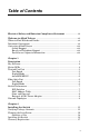
Table of Contents Electrical Safety and Emission Compliance Statement ......................iii Welcome to Allied Telesyn ......................................................................... vii Where to Find Web-based Guides .................................................................. vii Document Conventions ................................................................................... vii Contacting Allied Telesyn ..........................................................................
Table of Contents Chapter 3 Troubleshooting ........................................................................................... 19 Appendix A Technical Specifications ............................................................................ 21 Physical ............................................................................................................ 21 Temperature .................................................................................................... 21 Electrical Rating .
Welcome to Allied Telesyn This guide contains instructions on how to install the AT-FS20x and AT-FS202SC/FSx Series switches. Where to Find Web-based Guides The Allied Telesyn web site at www.alliedtelesyn.com offers you an easy way to access the most recent documentation, software, and technical information for all of our products. For product guides, select “Support & Services” from our web site. Document Conventions This guide uses the following conventions: Note Notes provides additional information.
Welcome to Allied Telesyn Contacting Allied Telesyn This section provides Allied Telesyn contact information for technical support as well as sales or corporate information. Online Support You can request technical support online by accessing the Allied Telesyn Knowledge Base from the following web site: www.alliedtelesyn.com/kb. You can use the Knowledge Base to submit questions to our technical support staff and review answers to previously asked questions.
Chapter 1 Description The AT-FS20x and AT-FS202SC/FSx Series Switches include the following models: ❑ AT-FS201 ❑ AT-FS202SC/FS2 ❑ AT-FS202 ❑ AT-FS202SC/FS3 ❑ AT-FS202SC/FS1 ❑ AT-FS202SC/FS4 The AT-FS20x Series switches are designed to extend the distance of your network by converting Fast Ethernet data between twisted-pair cabling and either multimode or single-mode fiber optic cabling.
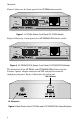
Description Figure 1 illustrates the front panel of an AT-FS20x Series switch. TX 100Base-FX RX 10Base-T/ 100Base-TX PWR CLASS 1 LASER PRODUCT LNK/ ACT LNK/ ACT FD/ COL FD/COL PORT 1 AT-FS202 PORT 2 AUTO NEG 100M FAST ETHERNET SWITCH IEEE 802.3 / 802.3U Figure 1 AT-FS20x Series Front Panel (AT-FS202 Model) Figure 2 illustrates a front panel of an AT-FS202SC/FSx Series switch.
AT-FS20x Series Installation Guide Table 1 lists the maximum operating distances for the switches. Table 1 Maximum Operating Distances 100Base-FX Model 10/100Base-TX Connector Maximum Operating Distance1 Connector Maximum Operating Distance2 AT-FS201 ST 2 km (1.2 mi) RJ-45 100 m (328 ft) AT-FS202 SC 2 km (1.2 mi) RJ-45 100 m (328 ft) ATFS202SC/ FS1 SC 15 km (9.3 mi) RJ-45 100 m (328 ft) ATFS202SC/ FS2 SC 40 km (24.8 mi) RJ-45 100 m (328 ft) ATFS202SC/ FS3 SC 75 km (46.
Description Key Features The AT-FS20x switches have the following features: ❑ LEDs for unit and port status ❑ Auto MDI/MDI-X ❑ DIP switches for configuring the ports ❑ Half- or full-duplex operation on both ports ❑ RJ-45 twisted-pair connector ❑ SC or ST fiber optic connector ❑ Data packet forwarding and filtering at full wire speed (10 Mbps to 100 Mbps, 100 Mbps to 100 Mbps, and 10 Mbps to 10 Mbps) ❑ Store and forward switching mode ❑ Automatic address learning and aging ❑ IEEE 802.
AT-FS20x Series Installation Guide LED Color Description 100M Green The twisted-pair port is operating at 100 Mbps. OFF The twisted-pair port is operating at 10 Mbps. Green The switch is operating in full-duplex mode. OFF The switch is operating in half-duplex mode. Blinking A collision has been detected on the port. Green Auto-Negotiation on the twisted-pair port is enabled. OFF Auto-Negotiation on the twisted-pair port is disabled.
Description The twisted-pair port on the switch can operated in either half- or full-duplex mode. You can set the duplex mode manually or allow the switch to set it automatically through Auto-Negotiation. With Auto-Negotiation, if the endnode is capable of full-duplex mode, the twisted-pair port is set automatically to full-duplex mode. If the end-node is capable of half-duplex mode, the port is set automatically to half-duplex mode.
AT-FS20x Series Installation Guide Switch Performance The AT-FS20x switches have the following performance values: ❑ 148,800 pps for 100 Mbps and 14,880 pps for 10 Mbps for full wire speed forwarding and filtering ❑ 200 Mbps maximum throughput in 100 Mbps, full-duplex mode ❑ 20 Mbps maximum throughput in 10 Mbps, full-duplex mode ❑ Storage for up to 4,000 MAC addresses ❑ 280 kilo bytes (per port) packet buffer ❑ Low latency 15.
Description Store and Forward The AT-FS20x switches support store and forward switching at Fast Ethernet full-wire speed in 100 Mbps, half- or full-duplex mode. Packets entering each port are stored in buffers. Once the packet is received, the switch forwards or discards the packet, depending on its destination address and error status. This ensures that only error-free packets destined for another segment are transferred across the switch, reducing the network load.
AT-FS20x Series Installation Guide Figure 4 illustrates a topology using one AT-FS202 switch to interconnect two small networks of stackable hubs.
Description 10
Chapter 2 Installing the Switch This chapter explains how to install an AT-FS20x and AT-FS202SC/FSx Series switches. These switches can be installed on a desktop or in an AT-MCR12 chassis. The procedures provided in this chapter are for installation on a desktop. To install a switch in the AT-MCR12 chassis, see the AT-MCR12 Chassis Installation Guide. Verifying Package Contents Make sure the following items are included in your package.
Installing the Switch Planning the Installation Be sure to observe the following guidelines when planning the installation of your switch. ❑ The end-node connected to the 100Base-FX fiber optic port must be able to operate at 100 Mbps. ❑ The end-node connected to the 10Base-T/100Base-TX twisted-pair port can operate at either 10 Mbps or 100 Mbps. ❑ The end-node connected to a port on the switch can be a network adapter card, repeater, router, hub, or another switch.
AT-FS20x Series Installation Guide Maximum Operating Distance1 Maximum Allowable Loss Budget 50/125 or 62.5/ 125 micron multimode 2 km (1.2 mi) 13 dB at 1310 nm 50/125 or 62.5/ 125 multimode 2 km (1.2 mi) 13 dB at 1310 nm 9/125 micron single-mode 15 km (9.3 mi) 16 dB at 1310 nm AT-FS202SC/FS2 9/125 micron single-mode 40 km (24.8 mi) 30 dB at 1310 nm AT-FS202SC/FS3 9/125 micron single-mode 75 km (46.
Installing the Switch ❑ Refer to Table 5 for the cabling specifications for the fiber optic port operating in half-duplex mode.
AT-FS20x Series Installation Guide Installing the Switch This section provides a procedure for installing the AT-FS20x switches. When setting the DIP switches consider the following: ❑ Setting the Auto Neg DIP switch for the twisted-pair port to ON or OFF enables or disables auto-negotiation for the port. If you disable auto-negotiation, be sure to set the DIP switches for the port’s speed and duplex mode to match the speed and duplex mode of the end-node.
Installing the Switch Table 6 DIP Switch Settings (Continued) DIP Switch Number Port Setting Position Description 3 2 Duplex Mode Up The twisted-pair port is operating at half-duplex mode. Down The twisted-pair port is operating at full-duplex mode. 4 2 Auto Neg Up Down Auto-Negotiation on the twisted-pair port is OFF. Auto-Negotiation on the twisted-pair port is ON.
AT-FS20x Series Installation Guide 10. Connect the twisted-pair cable (or cables) to the end node. See Table 7 for information about setting the duplex mode. You must set the AT-FS20x switch and the end node to auto negotiate or make their port speeds match.
Installing the Switch 18
Chapter 3 Troubleshooting Follow the guidelines below to test and troubleshoot the installation in the event a problem occurs. Note Whenever the speed and/or duplex mode are changed during or after power ON, power OFF then power back ON the switch to load the new configuration. If the PWR LED is OFF, do the following: ❑ If the switch is installed on a desktop, check that the power adapter is securely connected to a power outlet.
Troubleshooting ❑ Make sure that the twisted-pair cable does not exceed 100 meters (328 feet) and that you are using a Category 3 or better cable for 10Base-T operation or a Category 5 or better cable for 100Base-TX operation. For information about maximum operating distances, see Table 1 on page 3. If the LNK/ACT LED for the fiber optic port is OFF, do the following: ❑ Verify that the end-node connected to the port is ON and is operating properly.
Appendix A Technical Specifications Physical Dimensions: WxDxH 10.5 cm x 9.5 cm x 2.5 cm (4.12 in x 3.75 in x 1.0 in) Weight: 294 g (10.
Technical Specifications Agency Certifications Safety Conforms to all standards normally supported by Allied Telesyn products including safety standards UL 1950, CSA 22.2 No. 950, TUV EN60950, EN60825 CE Compliant Standard CE Compliant IEEE 802.3, IEEE 802.
AT-FS20x Series Installation Guide Table 9 Fiber Optic Receiver Model Fiber Type 1 Fiber Optic Diameter (microns) Optical Wavelength Receiver Sensitivity (dBm) Min. Avg. Saturation AT-FS201 & AT-FS202 MMF 50/125 1310 nm -31.8 -34.5 -14.5 MMF 62.5/125 1310 nm -31.8 -34.5 -14.0 ATFS202SC/ FS1 SMF 9/125 1310 nm -31.0 -31.0 -8.0 ATFS202SC/ FS2 SMF 9/125 1310 nm -35.0 -38.0 0.0 ATFS202SC/ FS3 SMF 9/125 1310 nm -37.0 -37.0 -3.0 ATFS202SC/ FS4 SMF 9.125 1550 nm -37.
Technical Specifications Minimum Power/ Link Budget Average Minimum Signal Distance Loss (dB) Specs.2 Maximum Distance Specs. Model Fiber Type1 AT-FS202SC/ FS3 9/125 SMF 33.00 dB 35.00 dB 15 km (9.4 mi) 75 km (46 mi) AT-FS202SC/ FS4 9/125 SMF 34.0 35.5 dB 40 km (24.8 mi) 100 km (62 mi) 1. MMF = Multimode Fiber / SMF = Single-mode Fiber. 2. The recommended minimum range is stated in all cases where the maximum transmitter output power exceeds the receivers saturation level.
AT-FS20x Series Installation Guide Table 12 lists the 10Base-T/100Base-TX connector pins and their signals when the port is operating in either MDI or MDI-X configuration.
Technical Specifications 26
Appendix B Translated Safety and Emission Information Important: This appendix contains multiple-language translations for the safety statements in this guide. Wichtig: Dieser Anhang enthält Übersetzungen der in diesem Handbuch enthaltenen Sicherheitshinweise in mehreren Sprachen. Vigtigt: Dette tillæg indeholder oversættelser i flere sprog af sikkerhedsadvarslerne i denne håndbog. Belangrijk: Deze appendix bevat vertalingen in meerdere talen van de veiligheidsopmerkingen in deze gids.
Translated Safety and Emission Information Standards: This product meets the following standards. U.S. Federal Communications Commission Radiated Energy Note: This equipment has been tested and found to comply with the limits for a Class A digital device pursuant to Part 15 of FCC Rules. These limits are designed to provide reasonable protection against harmful interference when the equipment is operated in a commercial environment.
AT-FS20x Series Installation Guide USA/Canada Use a UL Listed/CSA Certified AC adapter of DC 12V, 500mA. Europe - EU Use TÜV licensed AC adapter of DC 12V, 500mA. UK Use a UK Safety Approved AC adapter of DC 12V, minimum 500mA. 13 Operating Temperature: This product is designed for a maximum ambient temperature of 40 degrees C. 14 All Countries: Install product in accordance with local and National Electrical Codes. Normen: Dieses Produkt erfüllt die Anforderungen der nachfolgenden Normen.
Translated Safety and Emission Information Standarder: Dette produkt tilfredsstiller de følgende standarder. 1 2 Radiofrekvens forstyrrelsesemission EN55022 Klasse A Advarsel: I et hjemligt miljø kunne dette produkt forårsage radio forstyrrelse. Bliver det tilfældet, påkræves brugeren muligvis at tage tilstrækkelige foranstaltninger. 3 Immunitet 4 Advarsel: Dette produkt skal bruges med afskærmede kabler for at overholde bestemmelserne vedrørende udstråling og støjimmunitet.
AT-FS20x Series Installation Guide 7 Waarshuwing Klasse-1 laser produkt. 8 Waarchuwing Neit in de straal staren. 9 Dit is een “Klasse 1 LED-produkt” Veiligheid 10 Gevaar Voor Blikseminslag Gevaar: Niet aan toestellen of kabels werken bij bliksem. 11 Ventilatiegaten niet blokkeren. 12 Stroom mag alleen via de adapter naar het apparaat toegevoerd worden. Europe - EU Gebruik een door TÜV gekeurde wisselstroomadapter van 12 Volt gelijkstroom, 500 milliampères.
Translated Safety and Emission Information 13 Température De Fonctionnement Ce matériel est capable de tolérer une température ambiante maximum de 40 degrés Celsius. 14 Pour Tous Pays: Installer le matériel conformément aux normes électriques nationales et locales. Standardit: Tämä tuote on seuraavien standardien mukainen.
AT-FS20x Series Installation Guide Standard: Questo prodotto è conforme ai seguenti standard. 1 Emissione RFI (interferenza di radiofrequenza) EN55022 Classe A 2 Avvertenza: in ambiente domestico questo prodotto potrebbe causare radio interferenza. In questo caso potrebbe richiedersi all'utente di prendere gli adeguati provvedimenti. 3 Immunità 4 Avvertenza: questo prodotto, se utilizzato con cavi schermati, è conforme alle norme sulle emissioni e sull’immunità.
Translated Safety and Emission Information 6 Laser 7 Advarsel Laserprodukt av klasse 1. 8 Advarsal Stirr ikke på strålen. 9 Dette er et “Klasse 1 LED produkt” EN60825 Sikkerhet 10 Fare For Lynnedslag Fare: Arbeid ikke på utstyr eller kabler i tordenvær. 11 Blokker Ikke Luftventilene 12 All strømtilførsel må komme fra adapteren.
AT-FS20x Series Installation Guide 13 Temperatura De Funcionamento Este produto foi projetado para uma temperatura ambiente máxima de 40 graus centígrados. 14 Todos Os Países: Instale o produto de acordo com as normas nacionais e locais para instalações elétricas. 1 Emisión RFI 2 Advertencia: en un entorno doméstico, este producto puede causar radiointerferencias, en cuyo caso, puede requerirse del usuario que tome las medidas que sean convenientes al respecto.
Translated Safety and Emission Information 5 Elsäkerhet TUV-EN60950, UL1950, CSA 950 6 Laser EN60825 7 Varning! Laserprodukt av klass 1. 8 Varning! Laserstrålning när enheten är öppen. 9 Detta är en “Klass 1 lysdiodprodukt” Säkerhet 10 Fara För Blixtnedslag Fara: Arbeta ej på utrustningen eller kablarna vid åskväder. 11 Blockera Inte Luftventilerna. 12 Endast anslutningsenheten får vara kraftkälla till centralen.