Overview of IBM Networking The IBM networking technologies described in this publication can be categorized as network-related or host-related technologies.
Overview of IBM Networking RSRB Note All commands supported on the Cisco 7500 series routers are also supported on the Cisco 7000 series routers. RSRB In contrast to Source-Route Bridging (SRB), which involves bridging between Token Ring media only, RSRB is a Cisco technique for connecting Token Ring networks over non-Token Ring network segments. (DLSw+ is the Cisco strategic method for providing this function.
Overview of IBM Networking RSRB Configuration Considerations Use IP encapsulation only over a TCP connection within complex meshed networks to support connections between peers that are separated by multiple hops and can potentially use multiple paths, and where performance is not an issue. Use direct encapsulation in point-to-point connections. In a point-to-point configuration, using TCP adds unnecessary processing overhead.
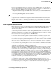
Overview of IBM Networking DLSw+ Note As previously stated, local acknowledgment for LLC2 is meant only for extreme cases in which communication is not possible otherwise. Because the router must maintain a full LLC2 session, the number of simultaneous sessions it can support before performance degrades depends on the mix of other protocols and their loads. The routers at each end of the LLC2 session execute the full LLC2 protocol, which can result in some overhead.
Overview of IBM Networking DLSw+ This section contains a brief overview of DLSw+: • DLSw Standard, page 205 • DLSw Version 2 Standard, page 205 • DLSw+ Features, page 206 DLSw Standard The DLSw standard, documented in RFC 1795, defines the switch-to-switch protocol between DLSw routers. The standard also defines a mechanism to terminate data-link control connections locally and multiplex the traffic from the data-link control connections to a TCP connection.
Overview of IBM Networking DLSw+ IP Multicast Multicast service avoids duplication and excessive bandwidth of broadcast traffic because it replicates and propagates messages to its multicast members only as necessary.
Overview of IBM Networking DLSw+ This section contains information on the following topics related to DLSw+ features: • Local Acknowledgment, page 207 • Notes on Using LLC2 Local Acknowledgment, page 209 • DLSw+ Support for Other SNA Features, page 210 DLSw+ is fully compatible with any vendor’s RFC 1795 implementation and the following features are available when both peers are using DLSw+: • Peer groups and border peers • Backup peers • Promiscuous and on-demand peers • Explorer firewalls an
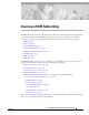
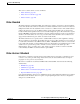
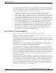
Overview of IBM Networking DLSw+ Figure 86 illustrates an LLC2 session in which a 37x5 on a LAN segment communicates with a 3x74 on a different LAN segment separated via a wide-area backbone network. Frames are transported between Router A and Router B by means of DLSw+. However, the LLC2 session between the 37x5 and the 3x74 is still end-to-end; that is, every frame generated by the 37x5 traverses the backbone network to the 3x74, and the 3x74, on receipt of the frame, acknowledges it.
Overview of IBM Networking DLSw+ 3x74 operates as if the acknowledgments it receives are from the 37x5. Router B looks like the 3x74 to 37x5. Because the frames do not have to travel the WAN backbone networks to be acknowledged, but are locally acknowledged by routers, the end machines do not time out, resulting in no loss of sessions.
Overview of IBM Networking DLSw+ If you are using NetBIOS applications, note that there are two NetBIOS timers—one at the link level and one at the next higher level. Local acknowledgment for LLC2 is designed to solve link timeouts only. If you are experiencing NetBIOS session timeouts, you have two options: Note • Experiment with increasing your NetBIOS timers and decreasing your maximum NetBIOS frame size. • Avoid using NetBIOS applications on slow serial lines.
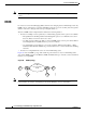
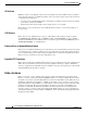
Overview of IBM Networking STUN and BSTUN Figure 88 VDLC Interaction with Higher-Layer Protocols DLSw+ SNASw Data-link users CLSI Ethernet VDLC Data-link controls 51909 Token Ring The higher-layer protocols make no distinction between the VDLC and any other data-link control, but they do identify the VDLC as a destination. In the example shown in , SNASw has two ports: a physical port for Token Ring and a logical (virtual) port for the VDLC.
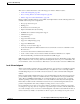
Overview of IBM Networking STUN and BSTUN Figure 89 Comparison of STUN in Passthrough Mode and Local Acknowledgment Mode 37x5 IBM 1 3x74 IBM1 WAN SDLC session SNA session TCP session SDLC session SDLC session SNA session Note 3x74 IBM 2 WAN S2839 37x5 IBM 1 To enable STUN local acknowledgment, you first enable the routers for STUN and configure them to appear on the network as primary or secondary SDLC nodes. TCP/IP encapsulation must be enabled.
Overview of IBM Networking STUN and BSTUN • Allows networks with IBM mainframes and communications controllers to share data using Cisco routers and existing network links. As an SDLC function, STUN fully supports the IBM SNA and allows IBM SDLC frames to be sent across the network media and shared serial links. illustrates a typical network configuration without STUN and the same network configured with STUN.
Overview of IBM Networking STUN and BSTUN Figure 90 shows the difference between an IBM network with STUN and one without STUN.
Overview of IBM Networking LLC2 and SDLC Parameters BSTUN Networks The Bisync feature enables your Cisco 2500, 3600, 4000, 4500, 4700, and 7200 series router to support devices that use the Bisync data-link protocol. This protocol enables enterprises to transport Bisync traffic over the same network that supports their SNA and multiprotocol traffic, eliminating the need for separate Bisync facilities. At the access router, traffic from the attached Bisync device is encapsulated in IP.
Overview of IBM Networking LLC2 and SDLC Parameters modifying the control field parameters, you can determine the number of acknowledgments sent for frames received and the level of polling used to determine available stations. In this manner, you can set the amount of resources used for frame checking and optimize the network load. SDLC is used as the primary SNA link-layer protocol for WAN links. SDLC defines two types of network nodes: primary and secondary.
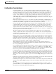
Overview of IBM Networking IBM Network Media Translation The Cisco Implementation of SDLC The Cisco SDLC implementation supports the following features: • Frame Relay Access Support (FRAS) With FRAS, a router functions as a Frame Relay Access Device (FRAD) for SDLC, Token Ring, and Ethernet-attached devices over a Frame Relay Boundary Network Node (BNN) link. Frame Relay access support is described in the chapter “Configuring SNA Frame Relay Access Support.
Overview of IBM Networking IBM Network Media Translation Figure 91 illustrates how SDLLC provides data link layer support for SNA communication. SNA Data Link Layer Support SNA Upper layers Data link layer SDLC SDLLC LLC LNX QLLC X.25 S3028 Figure 91 SDLLC Media Translation Features The SDLLC feature allows a PU 4, PU 2.
Overview of IBM Networking IBM Network Media Translation As part of its virtual telecommunications access method (VTAM) configuration, the IBM node on the Token Ring has knowledge of the SDLLC VTRA of the serial device with which it communicates. The SDLC VTRA and the SDLLC virtual ring number are a part of the SDLLC configuration for the router’s serial interface.
Overview of IBM Networking IBM Network Media Translation QLLC Conversion Qualified Logical Link Control (QLLC) is a data link protocol defined by IBM that allows SNA data to be transported across X.25 networks. (Although IBM has defined other protocols for transporting SNA traffic over an X.25 network, QLLC is the most widely used.) Figure 92 illustrates how QLLC conversion provides data link layer support for SNA communication.
Overview of IBM Networking IBM Network Media Translation QLLC Conversion Running on a Router with an Intermediate IP Network X.25/QLLC session TCP session LLC2 session Running RSRB Running QLLC X.25 network S3031 Figure 95 Token Ring IP network Router A Router B The Cisco Implementation of QLLC Conversion SNA uses QLLC and X.25 as link layer protocols to provide a reliable connection. QLLC itself processes QLLC control packets.
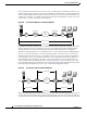
Overview of IBM Networking IBM Network Media Translation Figure 97 QLLC Conversion Between a Single 37x5 and Multiple 3x74s across an Arbitrary WAN 3270 Without local acknowledgment With local acknowledgment LLC2 session LLC2 session QLLC/X.25 session QLLC/X.25 session TCP session 3x74 VR1 VR2 37x5 Arbitrary WAN Token T0 Ring Router B Virtual ring 3x74 51924 Router A S0 X.
Overview of IBM Networking SNA FRAS Table 3 shows how the QLLC commands correspond to the SDLLC commands.
Overview of IBM Networking SNA FRAS Management service point support in FRAS allows the SNA network management application, NetView, to manage Cisco routers over the Frame Relay network as if it were an SNA downstream PU. FRAS provides dial backup over RSRB in case the Frame Relay network is down. While the backup Public Switched Telephone Network (PSTN) is being used, the Frame Relay connection is tried periodically. As soon as the Frame Relay network is up, it will be used.
Overview of IBM Networking SNA FRAS permanent virtual circuit, Cisco supports SAP multiplexing, which allows you to configure unique LLC2 SAPs for each downstream SNA device so that they can share a single permanent virtual circuit to an FEP. The Cisco IOS software is responsible for terminating the local data-link control frames (such as SDLC and Token Ring frames) and for modifying the data-link control frames to 802.2 compliant LLC frames.
Overview of IBM Networking NCIA NCIA Native Client Interface Architecture (NCIA) is a new software architecture introduced by Cisco to make accessing IBM SNA applications over routed internetworks more scalable and flexible. NCIA is a component of the Cisco IOS software. The architecture is intended to combine the benefits of the native SNA interface at end stations and mainframes with those of TCP/IP across the network backbone.
Overview of IBM Networking NCIA • The NCIA Server communicates with other components in router, such as RSRB, SNASw, DLSw+, and DSPU. • Supports both connect-in and connect-out. • The NCIA client/server model is independent of the upstream implementation. • It is an efficient protocol between client and server.
Overview of IBM Networking NCIA After the peer session has been established, the NDLC protocol establishes the circuit between the client and server. This circuit is used to transfer end-user data between the client and the server. Because the client and its target station are not on the same transport, they cannot form a direct, end-to-end circuit. Each client must form a circuit between the client and server, and the server must form another circuit between the server and the target station.
Overview of IBM Networking ALPS Migration Support Using a client/server model allows the NCIA Server feature to be independent of the upstream implementation, allowing it to be implemented in a network that is still using RSRB and in a DLSw+ network. It also greatly simplifies migration from RSRB to DLSw+, because it requires no changes at the client. A single NCIA server can support either approach (but not both).
Overview of IBM Networking DSPU and SNA Service Point Figure 104 ALPS Architecture Remote router ASCUs running ALC or UTS 25065 Mainframe with airline reservation system Network management system Remote router ASCUs running ALC or UTS The Cisco ALPS feature provides an end-to-end solution for airlines and central reservation systems.The ALPS feature is integrated in the Cisco IOS software and allows airlines to replace their existing hardware and software with Cisco routers.
Overview of IBM Networking DSPU and SNA Service Point Figure 105 shows a router functioning as a DSPU concentrator. Figure 105 Router Acting as a DSPU Concentrator LU LU PU 2 + 3 LUs RSRB PU 2 PU 5 Token Ring PU 2 + 1 LU DSPU concentrator supporting 4 PUs and 8 LUs Mainframe with 1 PU and 8 LUs defined PU 2 + 2 LUs S3223 Token Ring Typically, a router establishes one or more upstream connections with one or more hosts and many downstream connections with PU type 2 devices.
Overview of IBM Networking SNA Switching Services SNA Switching Services Note SNA Switching Services functionality supersedes all functionality previously available in the APPN feature in the Cisco IOS software. SNASw configuration will not accept the previous APPN configuration commands. Previous APPN users should use this chapter to configure APPN functionality using the new SNASw commands. SNASw provides an easier way to design and implement networks with SNA routing requirements.
Overview of IBM Networking Benefits of SNASw Scalable APPN Networks With the Branch Extender (BEX) function, the number of network nodes and the amount of broadcast traffic are reduced. IP Infrastructure Support Limiting SNASw routers to the data center and using the BEX function eliminates SNA broadcasts from the IP network. With Enterprise Extender (EE), SNA traffic is routed using the IP routing infrastructure while maintaining end-to-end SNA services.
Overview of IBM Networking HPR Capable SNA Routing Services HPR Capable SNA Routing Services SNASw provides the following SNA routing functions: • Routes SNA sessions between clients and target SNA data hosts. • Controls SNA traffic in a multiprotocol environment in conjunction with other Cisco IOS quality of service (QoS) features.
Overview of IBM Networking Enterprise Extender (HPR/IP) Figure 107 illustrates the BEX functionality. Figure 107 BEX Functionality Downstream devices CS/390 EN Emulated EN Emulated NN SNASw Cisco CIP PU 2.0 EN CS/390 NN 26186 LEN Enterprise Extender (HPR/IP) SNASw also supports the EE function. EE offers SNA HPR support directly over IP networks. EE also uses connectionless User Datagram Protocol (UDP) transport.
Overview of IBM Networking Usability Features Usability Features SNASw contains the following usability features designed to make SNA networks easier to design and maintain: • Dynamic CP Name Generation Support, page 236 • Dynamic SNA BTU Size, page 236 • DLUR Connect-Out, page 236 • Responsive Mode Adaptive Rate-Based Flow Control, page 236 • User-Settable Port Limits, page 237 Dynamic CP Name Generation Support When scaling the SNASw function to hundreds or thousands of nodes, many network admi
Overview of IBM Networking Management Enhancements Mode ARB architecture. Responsive Mode ARB addresses all the drawbacks of the earlier ARB implementation, providing faster ramp-up, better tolerance of lost frames, and better tolerance of multiprotocol traffic. User-Settable Port Limits SNASw offers full control over the number of devices supported by a specific port. The max-links configuration on the SNASw port controls the number of devices that are served by this port.
Overview of IBM Networking LAN and IP-Focused Connection Types MIB Support for Advanced Network Management Awareness SNASw supports the following Management Information Bases (MIBs): • IETF draft standard DLUR MIB (RFC 2232), which defines objects for monitoring and controlling network devices with DLUR (Dependent LU Requester) capabilities.
Overview of IBM Networking Cisco Transaction Connection same LAN. When using native LAN support, SNASw responds only to requests that target the MAC address configured on the local interface. Virtual Token Ring and SRB allow SNASw to respond to multiple MAC addresses over the same physical interface. Connection to Frame Relay Transport Technologies Virtual Token Ring and SRB connect SNASw to a SNA Frame Relay infrastructure.
Overview of IBM Networking Cisco Transaction Connection The CTRC software feature provides the following functionality: • CTRC allows Cisco routers to use the intersystem communication (ISC) protocol to provide a gateway between Customer Information Control System (CICS) clients (also known as common clients) running under Windows or UNIX on TCP/IP networks and CICS online transaction monitoring systems on IBM hosts.
Overview of IBM Networking Cisco Transaction Connection Figure 109 Cisco Router Configured with the CTRC Feature for CICS Communications CICS transaction monitor CICS client TCP/IP TCP/IP SNA TCP/IP SNA SNA APPC (LU 6.2) 26062 CTRC CTRC and DB2 CTRC enables Cisco routers to implement IBM’s DRDA over TCP/IP.
Overview of IBM Networking CMCC Adapter Hardware For a TCP/IP host connection, the router with CTRC routes the DRDA packets over TCP/IP without protocol changes. To use this TCP/IP passthrough feature of CTRC, the host database version must support direct TCP/IP access. Figure 111 illustrates such a configuration.
Overview of IBM Networking CMCC Adapter Hardware Figure 112 Cisco Mainframe Channel Connection Adapters Cisco 7500 Channel 1/0 series with CIP ESCON Channel 1/1 Parallel channel (Bus-and-Tag) IP SNA APPN HPR TN3270 LPAR1 LPAR2 APPN HPR TCP/IP SNA ESCON or parallel 51916 Cisco 7200 series with CPA Channel 1/0 Channel Interface Processor The CIP for the Cisco 7000 with RSP7000 and Cisco 7500 series routers is designed for high-end network environments that demand high-performance, high-port density
Overview of IBM Networking CMCC Adapter Hardware The Cisco 7200 series router supports online insertion and removal (OIR), which allows you to install or remove port adapters while the system is operating. Note In this chapter, references to Channel Port Adapter (CPA) correspond to both the ECPA and the PCPA. Refer to the Cisco 7200 Series Port Adapter Hardware Configuration Guidelines publication for more details.
Overview of IBM Networking CMCC Adapter Features for TCP/IP Environments Supported Environments The Cisco IOS software supports the following environments and features on the CMCC adapters: • TCP/IP Environments—CLAW, TCP/IP offload, IP host backup, CMPC+, and TN3270 server features • SNA and APPN Environments—CSNA, CMPC, and TN3270 server features CMCC Adapter Features for TCP/IP Environments The Cisco IOS software supports the following features for CMCC adapters in TCP/IP environments: • Common Lin
Overview of IBM Networking CMCC Adapter Features for TCP/IP Environments IP Host Backup You can connect multiple mainframes to a single CMCC adapter using an ESCON director. Often, these mainframes run using the ESCON Multiple Image Facility (EMIF), which permits the physical machine to be divided into multiple logical partitions (LPARs). By defining an unused partition on another mainframe, a user can move the operating system from a failed mainframe or mainframe partition to the unused partition.
Overview of IBM Networking CMCC Adapter Features for SNA Environments CMCC Adapter Features for SNA Environments The Cisco IOS software supports the following features for CMCC adapters in SNA environments: • Cisco SNA, page 247 • Cisco Multipath Channel, page 248 • TN3270 Server, page 248 Cisco SNA The CSNA feature provides support for SNA protocols to the IBM mainframe from Cisco 7500, Cisco 7200, and Cisco 7000 with RSP7000 series routers, using CMCC adapters (over both ESCON and parallel interfac
Overview of IBM Networking CMCC Adapter Features for SNA Environments Cisco Multipath Channel CMPC is Cisco System’s implementation of IBM’s MultiPath Channel (MPC) feature on Cisco 7500, Cisco 7200, and Cisco 7000 with RSP7000 series routers. CMPC allows VTAM to establish Advanced-Peer-to-Peer Networking (APPN) connections using both High Performance Routing (HPR) and Intermediate Session Routing (ISR) through channel-attached router platforms.
Overview of IBM Networking CMCC Adapter Features for SNA Environments The TN3270 server feature offers an attractive solution when the following conditions need to be supported in an SNA environment: • Maintaining an IP backbone while providing support for SNA 3270-type clients. • Offloading mainframe CPU cycles when using a TN3270 host TCP/IP stack with a TN3270 server. • Providing support for high session density or high transactions per second.
Overview of IBM Networking CMCC Adapter Features for SNA Environments To enable the TN3270 server feature, you must have a CMCC adapter installed in a Cisco 7000 with RSP7000, Cisco 7500 series router, or a Cisco 7200 router. For details about configuring the TN3270 server on a CMCC adapter, see the “Configuring the TN3270 Server” chapter in this publication.