BladeCenter Type 8677 Installation and User’s Guide Welcome. . . This Installation and User’s Guide contains information for setting up, configuring, and using your BladeCenter unit. For detailed information about your BladeCenter unit, view the publications on the Documentation CD. You can also find the most current information about your BladeCenter unit and servers on the IBM Web site at: http://www.ibm.com/pc/support Install the BladeCenter unit in the rack.
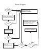
Server Support Server working properly? Yes Register your computer. Go to http://www.ibm.com/pc/register/ No Check all cables for loose connections and verify that all optional devices you ® installed are on the ServerProven list. You can view the ServerProven list at http://www.ibm.com/pc/compat/ Problem solved? View information about IBM support line at http://www.ibm.com/services/sl/products/ or view support telephone numbers at http://www.ibm.
ERserver BladeCenter Type 8677 Installation and User’s Guide
Note: Before using this information and the product it supports, read the general information in Appendix B, “IBM Statement of Limited Warranty Z125-4753-07 11/2002”, on page 61 and Appendix C, “Notices”, on page 77. Fifth Edition (August 2003) © Copyright International Business Machines Corporation 2002, 2003. All rights reserved. US Government Users Restricted Rights – Use, duplication or disclosure restricted by GSA ADP Schedule Contract with IBM Corp.
Contents Safety . . . . . . . . . . . . . . . . . . . . . . . . . . . . vii Chapter 1. Introduction . . . . . . . . . . . . About your documentation CD. . . . . . . . . . System requirements . . . . . . . . . . . . Starting the IBM Documentation Browser. . . . . Using the IBM Documentation Browser . . . . . Using the search feature . . . . . . . . . . . Related publications . . . . . . . . . . . . . Features and specifications . . . . . . . . . . . Notices and statements used in this book . . . . .
Rear system LED panel Blower module . . . . I/O module . . . . . Power module . . . . Management module. . System LED panel . . . . . . . . . . . . . . . . . . . . . . . . . . . . . . . . . . . . . . . . . . . . . . . . . . . . . . . . . . . . . . . . . . . . . . . . . . . . . . . . . . . . . . . . . . . . . . . . . . . . . . . . . . . . . . . . . . . . . 33 33 34 34 35 36 Chapter 4. Configuring your BladeCenter unit . . . . Setting up the remote connection . . . . . . . . . .
Part 3 - Warranty Information . . . . . . . . . . . . . . . . . . . 75 Appendix C. Notices . . . . . . . . . . . . . . . Edition notice . . . . . . . . . . . . . . . . . . Trademarks . . . . . . . . . . . . . . . . . . . Important notes. . . . . . . . . . . . . . . . . . Product recycling and disposal . . . . . . . . . . . . Battery return program . . . . . . . . . . . . . . . Electronic emission notices . . . . . . . . . . . . . Federal Communications Commission (FCC) statement . .
vi BladeCenter Type 8677: Installation and User’s Guide
Safety Before installing this product, read the Safety Information. Antes de instalar este produto, leia as Informações de Segurança. Pred instalací tohoto produktu si prectete prírucku bezpecnostních instrukcí. Læs sikkerhedsforskrifterne, før du installerer dette produkt. Lees voordat u dit product installeert eerst de veiligheidsvoorschriften. Ennen kuin asennat tämän tuotteen, lue turvaohjeet kohdasta Safety Information. Avant d’installer ce produit, lisez les consignes de sécurité.
Antes de instalar este producto, lea la información de seguridad. Läs säkerhetsinformationen innan du installerar den här produkten. Statement 1: DANGER Electrical current from power, telephone, and communication cables is hazardous. To avoid a shock hazard: v Do not connect or disconnect any cables or perform installation, maintenance, or reconfiguration of this product during an electrical storm. v Connect all power cords to a properly wired and grounded electrical outlet.
Statement 2: CAUTION: When replacing the lithium battery, use only IBM Part Number 33F8354 or an equivalent type battery recommended by the manufacturer. If your system has a module containing a lithium battery, replace it only with the same module type made by the same manufacturer. The battery contains lithium and can explode if not properly used, handled, or disposed of.
Statement 4: ≥ 18 kg (39.7 lb) ≥ 32 kg (70.5 lb) ≥ 55 kg (121.2 lb) CAUTION: Use safe practices when lifting. Statement 5: CAUTION: The power control button on the device and the power switch on the power supply do not turn off the electrical current supplied to the device. The device also might have more than one power cord. To remove all electrical current from the device, ensure that all power cords are disconnected from the power source.
Statement 8: CAUTION: Never remove the cover on a power supply or any part that has the following label attached. Hazardous voltage, current, and energy levels are present inside any component that has this label attached. There are no serviceable parts inside these components. If you suspect a problem with one of these parts, contact a service technician. Statement 12: CAUTION: The following label indicates a hot surface nearby.
Statement 20: CAUTION: To avoid personal injury, before lifting the unit, remove all the blades to reduce the weight. Statement 21: CAUTION: Hazardous energy is present when the blade is connected to the power source. Always replace the blade cover before installing the blade.
Chapter 1. Introduction The IBM® ERserver BladeCenter™ Type 8677 unit is based on IBM Enterprise X-Architecture™ technologies1. Your BladeCenter unit is a high-density, high-performance rack-mounted server system developed for medium-to-large businesses. It supports up to 14 blade servers, making it ideally suited for networking environments that require a large number of high-performance servers in a small amount of space.
Product name Eserver BladeCenter Machine type Model number Serial number 8677 _____________________________________________ _____________________________________________ The serial number and model number are on labels on the top, front, and rear of the chassis, as shown in the following illustration. Label Front Rear Label Label A set of user labels comes with each blade server.
About your documentation CD Your IBM BladeCenter unit comes with the IBM BladeCenter Type 8677 Documentation CD, which contains documentation for your system in Portable Document Format (PDF) and includes the IBM Documentation Browser to help you find information quickly. In addition to the documentation CD, your BladeCenter unit comes with the Rack Installation Instructions, which contain a rack-installation template and basic instructions for installing your system into a rack.
Note: To select multiple topics, press and hold down the Ctrl key while selecting your topics. 3. View selected topics. Click View Book. Adobe Acrobat Reader starts, and the selected topics are displayed. Using the search feature Complete the following steps to use the Documentation Browser search feature: 1. Type a key word in the Search field. 2. Click Search. The topics containing the search word are listed in order based on the number of occurrences. 3. Click a file to open it. 4.
Additional publications might be included on the IBM BladeCenter Documentation CD. Chapter 1.
Features and specifications The following table provides a summary of the features and specifications for your BladeCenter unit. Table 1. Features and specifications Media tray (on front): v Diskette drive: 1.44 MB v CD-ROM drive: IDE v Universal Serial Bus (USB) v1.
Notices and statements used in this book The caution and danger statements that appear in this book are also in the multilingual Safety Information book, which is on the IBM BladeCenter Documentation CD. Each statement is numbered for reference to the corresponding statement in the Safety Information book. The following notices and statements are used in the documentation: v Note: These notices provide important tips, guidance, or advice.
v Redundancy capabilities The redundant components in the rear of your BladeCenter unit enable continued operation if one of the components fails. – Power modules and blowers: Normally, the redundant power modules and blowers share the load. If one of the power modules or blowers fails, the non-failing power module or blower handles the entire load. You can then replace the failed blower or power module without shutting down the BladeCenter unit.
Each of these two additional I/O modules provides one internal connection to the optional I/O expansion card, up to 14 internal connections per I/O module. Reliability, availability, and serviceability Three of the most important features in server design are reliability, availability, and serviceability (RAS).
Major components of the BladeCenter Type 8677 unit The following illustration shows the locations of major components in your BladeCenter unit. Note: The illustrations in this document might differ slightly from your hardware.
Front view USB port Front system LED panel CD-ROM activity LED Diskette-drive activity LED CD-eject button Diskette-eject button Blade control panel System service card Blade servers Filler blades See Chapter 3, “BladeCenter unit power, controls, and indicators”, on page 29 for details about these components and indicators.
12 BladeCenter Type 8677: Installation and User’s Guide
Chapter 2. Installing options This chapter provides instructions for adding options to your BladeCenter unit. Some option-removal instructions are provided in case you need to remove one option to install another. Installing the BladeCenter unit in a rack Statement 20: CAUTION: To avoid personal injury, before lifting the unit, remove all the blades to reduce the weight. Statement 4: ≥ 18 kg (39.7 lb) ≥ 32 kg (70.5 lb) ≥ 55 kg (121.2 lb) CAUTION: Use safe practices when lifting.
some restrictions, hot-swap blade servers while the BladeCenter unit is running. For complete details about installing or removing a hot-swap component, see the detailed information in this chapter. v The blue color on components and labels identifies touch points where you can grip a component, move a latch, and so on. v You do not need to disconnect the BladeCenter unit from power to install or replace any of the hot-swap modules on the rear of the BladeCenter unit.
Installing and removing modules The procedures for installing or removing a module on the BladeCenter unit are nearly identical for all modules except the blower modules. To install or remove a blower module, see the BladeCenter Hardware Maintenance Manual and Troubleshooting Guide on the BladeCenter Documentation CD. To install or remove all other modules, follow the instructions in this section. Each module is keyed so that it can be inserted only in an appropriate bay.
I/O modules For blade server communication with the network, your BladeCenter unit supports from one to four hot-swap I/O modules. Table 2 identifies the type of I/O module you can install in each I/O-module bay. Go to the IBM Support Web site at http://www.ibm.com/pc/support/ to see the list of supported I/O modules. Your BladeCenter unit supports a minimum of one hot-swap Ethernet switch module or pass-thru module, in I/O-module bay 1 or 2.
Notes: 1. The enumeration of the Ethernet controllers in a blade server is operating-system dependent. You can verify the Ethernet controller designations a blade server uses through your operating system settings. 2. The routing of an Ethernet controller to a particular I/O-module bay depends on the type of blade server. You can verify which Ethernet controller is routed to which I/O-module bay by using the following test: a. Install only one Ethernet switch module or pass-thru module, in I/O-module bay 1.
Each pair of power modules is redundant. If either power module fails, the remaining power module continues to supply power, but there is no redundancy; the failed power module must be replaced as soon as possible. Important: 1. The power modules in a pair must match each other in capacity (wattage, amperage, and so forth). 2. In a pair of power modules, a power module that is not connected to an ac power source creates a non-redundant condition.
Statement 8: CAUTION: Never remove the cover on a power supply or any part that has the following label attached. Hazardous voltage, current, and energy levels are present inside any component that has this label attached. There are no serviceable parts inside these components. If you suspect a problem with one of these parts, contact a service technician. Complete the following steps to install a module: Note: These instructions assume the BladeCenter unit is connected to power. 1.
Removing a module Complete the following steps to remove a power module, management module, or I/O module. See the Hardware Maintenance Manual and Troubleshooting Guide on the BladeCenter Documentation CD for information about replacing a blower module. Note: These instructions assume the BladeCenter unit is connected to power. Statement 8: CAUTION: Never remove the cover on a power supply or any part that has the following label attached.
module you are removing before you remove it. (See the documentation that comes with the blade server for instructions for shutting down the blade server operating system and turning off the blade server.) 3. 4. 5. 6. b. If you are removing a management module, you might prefer to stop all management module local and remote sessions before proceeding, to avoid unexpected termination of sessions. Disconnect any cables from the module. For a power module, disconnect the power cord from the module.
Complete the following steps to install an acoustic module option on the BladeCenter unit: 1. Place the acoustic module over the blower modules, aligning the corners of the acoustic module back with the guides on the chassis, and pushing the shaft into the hole between the blower modules. 2. Rotate the acoustic module handle approximately 2 turns clockwise until it tightens the acoustic module firmly into place.
Blade server expansion options Some blade servers contain connectors for options that add capabilities to the blade server. You can add these options before installing the blade server in the BladeCenter unit. Go to http://www.ibm.com/pc/compat/ on the World Wide Web for a list of available options for your IBM blade server. I/O expansion option Some blade servers have connectors for adding an I/O expansion option, such as the IBM HS20 Fibre Channel Expansion Card.
2. Install any options needed, such as disk drives or memory, in the blade server. See the documentation that comes with the blade server for instructions. 3. Select the bay for the blade server. Notes: a. If a blade server has a SCSI storage expansion option installed on it, the blade server and expansion option require two adjacent blade bays. b. If you install a blade server or option in bay 7 through 14, you must install power modules in power bays 3 and 4. 4.
Important: Reinstalling a blade server into a different bay than the one from which it was removed could have unintended consequences. Some configuration information and update options are established according to bay number. You might need to reconfigure the blade server. If this is the initial installation for a blade server in the BladeCenter unit, you need to configure the blade server with the blade server Configuration/Setup Utility program and install the blade server operating system.
5. Place either a filler blade or another blade server in the bay within one minute. The spring-loaded doors will move out of the way as you insert the blade server or filler blade. Completing the installation After you connect the cables to the modules and route the cables (if necessary, see the Rack Installation Instructions for information about routing the cables), start the BladeCenter unit (if it is not already started) and verify that it is working properly, as follows: 1.
Video connector Your BladeCenter management module contains one standard video connector. The integrated video controller on each blade server is compatible with SVGA and VGA and communicates through this video port. Use this connector to connect a video monitor to the BladeCenter unit. 5 1 15 11 Keyboard connector Your BladeCenter management module contains one PS/2-style keyboard connector. Use this connector to connect a PS/2 keyboard to the BladeCenter unit.
The following illustration shows the Ethernet connector that is on the management module. 8 1 I/O-module connectors See the documentation that comes with each I/O module for a description of the connectors on the I/O module.
Chapter 3. BladeCenter unit power, controls, and indicators This section describes the controls and light-emitting diodes (LEDs) and how to start and shut down the BladeCenter unit. Starting the BladeCenter unit Important: For the LEDs on each system LED panel to function correctly, be sure to install the management module before starting the BladeCenter unit. See Chapter 2, “Installing options”, on page 13 for instructions for installing the management module.
Shutting down the BladeCenter unit You can shut down the BladeCenter unit by turning off the blade servers and disconnecting the BladeCenter unit from the power source. Complete the following steps to shut down the BladeCenter unit: 1. Refer to your blade server operating-system documentation for the proper procedure to shut down the operating system in the blade servers; then, shut down each operating system.
BladeCenter components, controls, and LEDs This section identifies the components, controls, and LEDs on the front and rear of your BladeCenter unit. Note: The illustrations in this document might differ slightly from your hardware. Front view This section identifies the components, controls, and LEDs on the front of your BladeCenter unit.
System service card: This card contains system service instructions and a writable area for your use. Hot-Plug Processor Blade CD Processor Blade Operator Panel Location Information Over-temperature System error Common Chassis FRUs IBM server xSeries home page http://www.ibm.com/eserver/xseries Download files, hints & tips, create custom profiles, and frequently asked questions http://www.ibm.
Rear view This section identifies the components and indicators on the rear of your BladeCenter unit. I/O module bay 3 I/O module 1 Power module bay 3 Blower module 1 Power module 1 AC DC Management module 1 AC DC Blower module 2 Power module bay 4 Management module bay 2 Power module 2 Rear system LED panel I/O module 2 I/O module bay 4 Rear system LED panel The LEDs on this panel provide status information for your BladeCenter unit. These LEDs duplicate the LEDs in the front system LED panel.
v Blower error: This amber LED is lit and stays lit when an error has been detected in the blower. The system error LED on the BladeCenter system LED panels is also lit. I/O module See the documentation that comes with each I/O module for a description of the LEDs on the I/O module. Power module AC power AC DC DC power Power module LEDs: These green LEDs indicate the condition of the power module.
Management module Management module error LED Active LED Power-on LED Ethernet link LED OK LINK TX/RX Ethernet activity LED IP reset button IP Management module LEDs: These LEDs provide status information about the management module and remote management connection. For additional information, see the “Light Path Diagnostics” section in the Hardware Maintenance Manual and Troubleshooting Guide on the IBM BladeCenter Documentation CD.
DHCP server on the network the BladeCenter unit is connected to, it takes two minutes before the management module uses the default (static) IP address. When the DHCP search times out and the management module uses the static IP address, you can change the management module configuration so that it will not attempt to locate a DHCP server (MM Control → Network Interfaces → External Network Interface → DHCP, select Static only).
Chapter 4. Configuring your BladeCenter unit The BladeCenter unit automatically detects the modules and blade servers that are installed and stores the vital product data (VPD) information. When the BladeCenter unit is started, it automatically configures the remote management port on the management module, so that you can configure and manage the BladeCenter unit and blade servers.
Notes: 1. For best results when using the Web browser, set the monitor to 256 colors. Use only the video resolutions and refresh rates given in the following table. These are the only video resolution and refresh rate combinations that are supported for all system configurations. Resolution Refresh rate 640x480 60 Hz 640x480 72 Hz 640x480 75 Hz 640x480 85 Hz 800x600 60 Hz 800x600 72 Hz 800x600 75 Hz 800x600 85 Hz 1024x768 60 Hz 1024x768 75 Hz 2.
Setting up the remote connection To configure and manage the BladeCenter unit and blade servers, you must first set up the remote connection through the external Ethernet port on the management module. Cabling the Ethernet port Complete the following steps to connect the Ethernet cable to the management module: 1. Connect one end of a Category 5 or higher Ethernet cable to the Ethernet port on the management module. Connect the other end of the Ethernet cable to the network. 2.
Web interface (MM Control → Network Interfaces → External Network Interface (eth0)). The default IP address is 192.168.70.125, the default subnet address is 255.255.255.0, and the default host name is MMxxxxxxxxxxxx, where xxxxxxxxxxxx is the burned-in medium access control (MAC) address. The MAC address is on a label on the management module, below the IP reset button. OK LINK TX/RX MAC address IP Notes: 1.
For the IBM Director software to discover the BladeCenter unit, your network must initially provide connectivity from the IBM Director server to the BladeCenter management-module Ethernet port. To establish connectivity, the management module attempts to use DHCP to acquire its initial IP address for the Ethernet port. If the DHCP request fails, the management module uses a static IP address. Therefore, the DHCP server (if used) must be on the management LAN for your BladeCenter unit. Notes: 1.
4. Shut down the blade server, insert a DOS startable diskette into the diskette drive, and then restart the blade server. 5. When the A:\ prompt appears, turn off the blade server using the power-control button. 6. Issue the Wake on LAN command (magic packet) from the remote computer. If the Wake on LAN feature was properly configured and is functioning, the single blade server will wake up.
The BladeCenter management and configuration window opens. Note: The upper left corner of the management and configuration window shows the location and identity of the active management module. Management and configuration program options From the management and configuration program main menu, you can select settings that you want to view or change.
v If you plan to use redundant management modules and want both to use the same IP address, disable DHCP and configure and use the static IP address (the IP configuration information will be transferred to the redundant management module automatically when needed). Otherwise, configure the DHCP setting as you prefer. You need to configure the static IP address only if DHCP is disabled. – IP address - The IP address for the management module.
Using IBM Director The IBM Director program is a system-management product that comes with the BladeCenter unit. Through the remote connection on the management module, you can use the IBM Director software at the IBM Director console to configure the BladeCenter unit, modify the configuration, and set up more advanced features. Notes: 1. Some tasks, such as software distribution, require an in-band connection from the Director server through a campus (public) LAN to a switch module port. 2.
v Drag the wizard task from the right-most pane (under BladeCenter in the task list) to any of the selected BladeCenter units (managed objects). The wizard starts, and guides you through the login and configuration tasks needed. The following illustration shows the main window on the BladeCenter Deployment wizard. Using Remote Deployment Manager Version 4.1 or later You can use the Remote Deployment Manager (RDM) Version 4.
What to configure You need to configure the switch module IP addresses and subnet mask through the management module Web interface to have switch module communication with the management module and remote management station (IBM Director server and console, for example). This is in addition to the IP addresses configured in the management module.
Note: When failover occurs on a blade server, the secondary Ethernet controller takes over network communication, using the I/O module associated with that controller. v Install a pair of Ethernet switch modules in I/O-module bays 1 and 2. Note: You can install a pass-thru module that is connected to an external Ethernet switch in either or both of these I/O-module bays. v Configure the Ethernet switch modules and your network infrastructure so that they can direct traffic to the same destinations.
1 Gbps links 1 Gbps or 100 Mbps links Switch A 1 2 3 4 5 6 7 8 9 10 11 12 13 14 10/100 Mbps Mgmt Mod 100 Mbps links Switch B MAC MAC MAC 1a 2a 3a 1b 2b 3b 1 Gbps links Note: 2nd switch module is optional Each blade server has two independent Ethernet controllers, each with its own MAC address and a dedicated 1000-Mbps link to one of the switch modules in I/O module bays 1 and 2 (Controller 1 to Switch A and Controller 2 to Switch B in this diagram).
Multiport aggregation group 1 Gbps or 100 Mbps links Switch A 1 2 3 4 5 6 7 8 L2 Switch 9 10 11 12 13 14 Mgmt Mod 10/100 Mbps management links Switch B Switch A 1 2 3 4 5 6 7 8 9 10 11 12 13 14 Mgmt Mod Switch B L2+ Switch Dual external switches IBM Director - Chassis management - Application deployment - Internal switches Establishment backbone L2+ Switch Switch A 1 2 3 4 5 6 7 8 9 10 11 12 13 14 Mgmt Mod Switch B Network administrator - Infrastructure management - Ne
Chapter 5. Sharing resources among the blade servers Your Eserver BladeCenter Type 8677 unit provides resources that are available to all blade servers at all times, such as power modules, cooling, system management, and network I/O modules; no user intervention is required. Some resources are selectable for use by a single blade server at a time, such as the CD-ROM drive, diskette drive, and USB port unit (media tray), or the keyboard-video-mouse unit.
current KVM owner. The video from blade server 14 displays on the monitor briefly until the management module uses its NVRAM values to reestablish ownership of the KVM and media tray (CD-ROM drive, diskette drive, and USB port). After that, the video from the blade server that is the current KVM owner is displayed on the monitor. Attention: Do not switch the CD-ROM drive, diskette drive, and USB port to another blade server while a transaction is taking place on either the CD-ROM or the diskette drive.
Chapter 6. Solving problems This section provides basic troubleshooting information to help you solve some common problems that might occur while setting up your BladeCenter unit. If you cannot locate and correct the problem using the information in this section, see the Hardware Maintenance Manual and Troubleshooting Guide on the IBM BladeCenter Documentation CD for more information.
Troubleshooting charts You can use the troubleshooting charts in this section to find solutions to problems that have definite symptoms. Note: The symptoms for monitor, keyboard, and mouse apply only to the devices connected to the management module; they do not apply to the remote console. See the Hardware Maintenance Manual and Troubleshooting Guide on the IBM BladeCenter Documentation CD for more detailed information about testing the BladeCenter unit.
Device Suggested action The monitor has screen jitter, or the screen image is wavy, unreadable, rolling, or distorted. If the monitor self-tests show the monitor is working correctly, consider the location of the monitor. Magnetic fields around other devices (such as transformers, appliances, fluorescent lights, and other monitors) can cause screen jitter or wavy, unreadable, rolling, or distorted screen images. If this happens, turn off the monitor.
Options problems Device Suggested action An IBM option that was just installed does not work. Make sure that: v The option is designed for the BladeCenter unit. See the “Server Support” flowchart on the inside of the front cover for information about obtaining ServerProven® compatibility information from the World Wide Web. v You followed the installation instructions that come with the option. v The option is installed correctly. v You have not loosened any other installed options or cables.
Light path diagnostics LEDs The system-error LED on the system LED panel is lit when certain system errors occur. If the system-error LED on your BladeCenter unit is lit, use the following table to help determine the cause of the error and the action you should take. Table 3. Light path diagnostics Lit LED Cause Action BladeCenter system LED panel Location A condition has occurred in the BladeCenter unit that has caused the remote system management to identify the BladeCenter unit as needing attention.
Table 3. Light path diagnostics (continued) Lit LED Cause Action A critical error has occurred in the power module. Reseat the power module. If the problem remains, replace the module. If your BladeCenter unit has a redundant module for this power module, the BladeCenter unit continues to function using the redundant module. The blower has failed or is operating too slowly. Reseat the blower module. If the problem remains, replace the blower module as soon as possible, to regain cooling redundancy.
Appendix A. Getting help and technical assistance If you need help, service, or technical assistance or just want more information about IBM products, you will find a wide variety of sources available from IBM to assist you. This appendix contains information about where to go for additional information about IBM and IBM products, what to do if you experience a problem with your Eserver or IntelliStation® system, and whom to call for service, if it is necessary.
You can find service information for your IBM products, including supported options, at http://www.ibm.com/pc/support/. If you click Profile from the support page, you can create a customized support page.
Appendix B. IBM Statement of Limited Warranty Z125-4753-07 11/2002 Part 1 - General Terms Part 1 - General Terms This Statement of Limited Warranty includes Part 1 - General Terms, Part 2 Country-unique Terms, and Part 3 - Warranty Information. The terms of Part 2 replace or modify those of Part 1. The warranties provided by IBM in this Statement of Limited Warranty apply only to Machines you purchase for your use, and not for resale.
The warranty is voided by removal or alteration of identification labels on the Machine or its parts. IBM does not warrant uninterrupted or error-free operation of a Machine. Any technical or other support provided for a Machine under warranty, such as assistance via telephone with “how-to” questions and those regarding Machine set-up and installation, is provided WITHOUT WARRANTIES OF ANY KIND.
Before IBM or your reseller exchanges a Machine or part, you agree to remove all features, parts, options, alterations, and attachments not under warranty service. You also agree to: 1. ensure that the Machine is free of any legal obligations or restrictions that prevent its exchange; 2. obtain authorization from the owner to have IBM or your reseller service a Machine that you do not own; and 3. where applicable, before service is provided: a.
PROFITS, BUSINESS REVENUE, GOODWILL OR ANTICIPATED SAVINGS. SOME STATES OR JURISDICTIONS DO NOT ALLOW THE EXCLUSION OR LIMITATION OF INCIDENTAL OR CONSEQUENTIAL DAMAGES, SO THE ABOVE LIMITATION OR EXCLUSION MAY NOT APPLY TO YOU. SOME STATES OR JURISDICTIONS DO NOT ALLOW LIMITATIONS ON HOW LONG AN IMPLIED WARRANTY LASTS, SO THE ABOVE LIMITATION MAY NOT APPLY TO YOU.
Limitation of Liability: The following replaces item 1 of this section: 1. damages for bodily injury (including death) or physical harm to real property and tangible personal property caused by IBM’s negligence; and Governing Law: The following replaces “laws of the country in which you acquired the Machine” in the first sentence: laws in the Province of Ontario.
be filled by the respective nominating party. Proceedings shall continue from the stage they were at when the vacancy occurred. If one of the parties refuses or otherwise fails to appoint an arbitrator within 30 days of the date the other party appoints its, the first appointed arbitrator shall be the sole arbitrator, provided that the arbitrator was validly and properly appointed. All proceedings shall be conducted, including all documents presented in such proceedings, in the English language.
MALAYSIA Limitation of Liability: The word “SPECIAL” in item 3 of the fifth paragraph is deleted. NEW ZEALAND What this Warranty Covers: The following paragraph is added to this section: The warranties specified in this section are in addition to any rights you may have under the Consumer Guarantees Act 1993 or other legislation which cannot be excluded or limited.
All proceedings shall be conducted, including all documents presented in such proceedings, in the English language. The English language version of this Statement of Limited Warranty prevails over any other language version. SINGAPORE Limitation of Liability: The words “SPECIAL” and “ECONOMIC” in item 3 in the fifth paragraph are deleted.
“the laws of France” in Algeria, Benin, Burkina Faso, Cameroon, Cape Verde, Central African Republic, Chad, Comoros, Congo Republic, Djibouti, Democratic Republic of Congo, Equatorial Guinea, French Guiana, French Polynesia, Gabon, Gambia, Guinea, Guinea-Bissau, Ivory Coast, Lebanon, Madagascar, Mali, Mauritania, Mauritius, Mayotte, Morocco, New Caledonia, Niger, Reunion, Senegal, Seychelles, Togo, Tunisia, Vanuatu, and Wallis & Futuna; 3) “the laws of Finland” in Estonia, Latvia, and Lithuania; 4) “the law
Poland, Romania, Russia, Slovakia, Slovenia, Tajikistan, Turkmenistan, Ukraine, Uzbekistan, and FR Yugoslavia all disputes arising out of this Statement of Limited Warranty or related to its violation, termination or nullity will be finally settled under the Rules of Arbitration and Conciliation of the International Arbitral Center of the Federal Economic Chamber in Vienna (Vienna Rules) by three arbitrators appointed in accordance with these rules.
The above limitation shall not apply to damages for bodily injuries (including death) and damages to real property and tangible personal property for which IBM is legally liable. 2.
The second paragraph does not apply. What IBM Will Do to Correct Problems: The following is added to this section: During the warranty period, transportation for delivery of the failing Machine to IBM will be at IBM’s expense. Limitation of Liability: The following paragraph is added to this section: The limitations and exclusions specified in the Statement of Limited Warranty will not apply to damages caused by IBM with fraud or gross negligence and for express warranty.
During the warranty period, transportation for delivery of the failing Machine to IBM will be at IBM’s expense. Limitation of Liability: The following paragraph is added to this section: The limitations and exclusions specified in the Statement of Limited Warranty will not apply to damages caused by IBM with fraud or gross negligence and for express warranty.
3. Except as provided in items 1 and 2 above, IBM’s entire liability for actual damages for any one Default will not in any event exceed the greater of 1) EUR 125,000, or 2) 125% of the amount you paid for the Machine directly relating to the Default. Items for Which IBM is Not Liable Save with respect to any liability referred to in item 1 above, under no circumstances is IBM, its suppliers or resellers liable for any of the following, even if IBM or they were informed of the possibility of such losses: 1.
Sterling 75,000, or 2) 125% of the total purchase price payable or the charges for the Machine directly relating to the Default. These limits also apply to IBM’s suppliers and resellers. They state the maximum for which IBM and such suppliers and resellers are collectively responsible.
IBM will ship CRU parts to you for your replacement. If IBM instructs you to return the replaced CRU, you are responsible for returning it to IBM in accordance with IBM’s instructions. If you do not return the defective CRU, if IBM so instructs, within 30 days of your receipt of the replacement CRU, IBM may charge you for the replacement. 2. On-site Service IBM or your reseller will either repair or exchange the failing Machine at your location and verify its operation.
Appendix C. Notices This publication was developed for products and services offered in the U.S.A. IBM may not offer the products, services, or features discussed in this document in other countries. Consult your local IBM representative for information on the products and services currently available in your area. Any reference to an IBM product, program, or service is not intended to state or imply that only that IBM product, program, or service may be used.
Trademarks The following terms are trademarks of International Business Machines Corporation in the United States, other countries, or both: Active Memory Active PCI Active PCI-X Alert on LAN BladeCenter C2T Interconnect Chipkill EtherJet e-business logo FlashCopy IBM IntelliStation NetBAY Netfinity NetView OS/2 WARP Predictive Failure Analysis PS/2 ServeRAID ServerGuide ServerProven TechConnect Tivoli Tivoli Enterprise Update Connector Wake on LAN XA-32 XA-64 X-Architecture XceL4 XpandOnDemand xSeries Lo
When referring to hard disk drive capacity or communications volume, MB stands for 1 000 000 bytes, and GB stands for 1 000 000 000 bytes. Total user-accessible capacity may vary depending on operating environments. Maximum internal hard disk drive capacities assume the replacement of any standard hard disk drives and population of all hard disk drive bays with the largest currently supported drives available from IBM.
Electronic emission notices IBM BladeCenter Type 8677 Federal Communications Commission (FCC) statement Note: This equipment has been tested and found to comply with the limits for a Class A digital device, pursuant to Part 15 of the FCC Rules. These limits are designed to provide reasonable protection against harmful interference when the equipment is operated in a commercial environment.
This product has been tested and found to comply with the limits for Class A Information Technology Equipment according to CISPR 22/European Standard EN 55022. The limits for Class A equipment were derived for commercial and industrial environments to provide reasonable protection against interference with licensed communication equipment. Attention: This is a Class A product.
For units intended to be operated at 115 volts: Use a UL-listed and CSA-certified cord set consisting of a minimum 18 AWG, Type SVT or SJT, three-conductor cord, a maximum of 15 feet in length and a parallel blade, grounding-type attachment plug rated 15 amperes, 125 volts. For units intended to be operated at 230 volts (U.S.
IBM power cord part number Used in these countries and regions 14F0087 Israel 1838574 Antigua and Barbuda, Aruba, Bahamas, Barbados, Belize, Bermuda, Bolivia, Brazil, Caicos Islands, Canada, Cayman Islands, Costa Rica, Colombia, Cuba, Dominican Republic, Ecuador, El Salvador, Guam, Guatemala, Haiti, Honduras, Jamaica, Japan, Mexico, Micronesia (Federal States of), Netherlands Antilles, Nicaragua, Panama, Peru, Philippines, Taiwan, United States of America, Venezuela 24P6858 Korea (Democratic People’s
84 BladeCenter Type 8677: Installation and User’s Guide
Index A diskette eject button 31 diskette drive activity LED 31 specifications 6 ac power LED 34 acoustic attenuation module about 21 installing 22 removing 22 acoustical noise emissions 6 activity LED CD-ROM drive 31 diskette drive 31 availability features 9 E eject button CD 31 diskette 31 electrical input 6 electronic emission Class A notice 80 environment 6 Ethernet configuring 48 configuring remote connection 39 integrated on blade server system board 48 port, cabling 39 Ethernet connector, remote m
K O keyboard connector 27 options installing 13 over-temp LED 36 L LEDs ac power 34 active, management module 35 blower 34 CD-ROM drive activity 31 dc power 34 diskette drive activity 31 error blower 34 management module 35 system 36 Ethernet-link status 35, 39 front of server 36 front view 31 information system LED panel 36 location blade server 36 BladeCenter 36 over-temp 36 power-on management module 35 system LED panel 36 rear view 33 system error blade server 36 system LED panel 36 system LED pane
system reliability 14 T temperature 6 trademarks 78 troubleshooting 53 charts 54 U United States electronic emission Class A notice United States FCC Class A notice 80 utility Configuration/Setup 42 80 V video connector 27 video output, unexpected or blank 51 W Web browsers, supported 37 Web site compatible options 14 weight 6 Index 87
88 BladeCenter Type 8677: Installation and User’s Guide
Part Number: 59P6595 Printed in U.S.A.