CI5VGM Series Full-Size Pentium All-in-one CPU Card Version 1.
Copyright Notice This publication is protected by copyright and all rights are reserved. No part of it may be reproduced or transmitted by any means or in any form, without prior consent of the original manufacturer. The information in this document has been carefully checked and is believed to be accurate. However, the original manufacturer assumes no responsibility for any inaccuracies that may appear in this manual.
Contents Contents Chapter 1 Introduction............................................. 1 Checklist..................................................................... 3 Description ................................................................. 3 Features ...................................................................... 4 Specifications ............................................................. 4 Intelligence ................................................................. 7 Board Dimensions ...
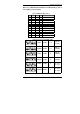
Chapter 1 Introduction Below are additional information for LCD Panel Type Select and settings for newer CPUs SW3: LCD Panel Type Select 1 2 3 ON ON ON OFF ON ON ON OFF ON OFF OFF ON ON ON OFF 4 TFT LCD Panel ON 640x480 –18 ON 800x600 –18 ON 1024x768 –18 ON 1024x768 –18+18 ON 1280x1024 –18+18 1 2 3 ON ON ON OFF ON ON ON OFF ON OFF OFF ON ON ON OFF 4 DSTN LCD Panel OFF 640x480 –16 OFF 800x600 –16 OFF 1024x768 –16 OFF 1024x768 –24 OFF 1280x1024 –24 Settings for New Cyrix/AMD CPUs 63MHz 3.
Chapter 1 Introduction 1 Introduction This manual is designed to give you information on the CI5VGM CPU card. It is divided into the following sections: Checklist .......................................................................................3 Description....................................................................................3 Features.........................................................................................4 Specifications.................................................
Chapter 1 Introduction Checklist Please check that your package is complete and contains the items below. If you discover damaged or missing items, please contact your dealer.
Chapter 1 Introduction Features • Socket 7, CPU Speed 90~550MHz • Bus Speed 60/66/75/83/95/100MHz • VIA MVP3 AGPset • Up to 384MB of system memory, ECC function supported • Trident 9520/25 AGP VGA chipset for LCD & CRT display • YAMAHA 715 Audio Chip • 16 level programmable watchdog timer, from 0-30 seconds • High speed bi-directional SPP/ECP/EPP parallel port • ISA High Drive • 2MB~72MB DiskOnChip support • Hardware Monitoring • Win95 shut-off, Modem ring-on via ATX power • 10/100M Base-T Ethernet interfa
Chapter 1 Introduction • Memory Sockets: Three 168-pin DIMM sockets Memory types: SDRAM (Synchronous DRAM) DIMMs: EDO DRAM or SDRAM (Synchronous DRAM) DIMM Size: 8MB, 16MB, 32MB, 64MB, 128MB • BIOS: Y2K compliant Award BIOS, PnP support • FLASH EEPROM (256KB) for BIOS update • ISA Plug and Play (PnP) extension • Power management • DMI BIOS Support: Desktop Management Interface (DMI) allows users to download system hardware-level information such as CPU type, CPU speed, internal/external frequencies and mem
Chapter 1 Introduction • Onboard Audio (optional): The onboard audio consists of a YAMAHA YMF715-S (OPL3-SA3) single audio chip that integrates OPL3 and its DAC, 16bit Sigma-delta CODEC, MPU401 MIDI interface, joystick with timer, and a 3D enhanced controller including all the analog components which is suitable for multimedia application. • DiskOnChip: The M-Systems flask disk supports system boot and storage capacity from 2MB to 72MB.
Chapter 1 Introduction Intelligence • Temperature Monitoring and Alert: A sensor for the CPU temperature on the CI5VGM monitors the CPU temperature and alerts the user through the speaker or buzzer when temperature exceeds the safe heat level. • Windows 95 shut-off: Allows shut-off control from within Windows 95 and through an ATX power supply. • Modem ring-on: Allows system powering on through an external modem and through an ATX power supply.
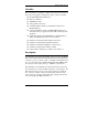
Chapter 1 Introduction Board Dimensions 8 CI5VGM User’s Manual
Chapter 1 Introduction This page is intentionally left blank .
Chapter 2 Installations 2 Installations This chapter provides information on how to use the jumpers and connectors on the CI5VGM in order to set up a workable system. The topics covered are: CPU Installation..........................................................................11 Memory Installation....................................................................12 Jumpers on the CI5VGM ............................................................14 Connectors on the CI5VGM ...........................
Chapter 2 Installations CPU Installation The CI5VGM Industrial CPU Card supports a ZIF processor socket for Pentium-level processors. Unlike PGA sockets, ZIF (Zero Insertion Force) sockets come with a lever to secure the processor. Make sure the notch on the corner of the CPU corresponds with the notch on the inside of the socket. After you have installed the processor into the ZIF socket, check if the jumpers for the CPU type and speed are correct.
Chapter 2 Installations Memory Installation The CI5VGM Industrial CPU Card supports three 168-pin DIMM sockets for a maximum total memory of 384MB. The memory modules can come in sizes of 16MB, 32MB, 64MB, 128MB in EDO DRAM or SDRAM type. In populating the DIMM sockets, DIMM1, DIMM2 or DIMM3 can be populated first. Refer to the following table on how to configure the memory. NOTE: You must install memory modules of the same type, either all SDRAM or all EDO DRAM. 168Pin DIMM (3.
Chapter 2 Installations 168Pin DIMM (3.
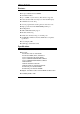
Chapter 2 Installations Jumpers on the CI5VGM The jumpers on the CI5VGM allows you to configure your CPU card according to the needs of your applications. If you have doubts about the best jumper configuration for your needs, contact your dealer or sales representative. The following table lists the connectors on CI5VGM and their respective functions. Jumper Locations on the CI5VGM ....................................15 SW1(1-8): CPU Frequency Selector ..................................
Chapter 2 Installations Jumper Locations on the CI5VGM CI5VGM User’s Manual 15
Chapter 2 Installations SW1(1-8): CPU Frequency Selector For Intel Pentium, IDT WinChip 2-3D / C6 SW1 CPU Clock AGP Clock Multiplier CPU FREQ. 60MHz 60MHz 1.5x P54C-90 66MHz 66MHz 1.5x P54C-100 60MHz 60MHz 2x P54C-120 66MHz 66MHz 2x P54C-133 60MHz 60MHz 2.5x P54C-150 66MHz 66MHz 2.5x P54C/P55C-16 6 60MHz 60MHz 3x C6-180 66MHz 66MHz 3x P54C/P55C-200 WinChip 2-3D / C6-200 66MHz 66MHz 3.
Chapter 2 Installations For Cyrix 6x86, 6x86L, 6x86MX. MII CPU SW1 CPU Clock AGP Clock 66MHz 66MHz 2x P166+ (133MHz) 75MHz 75MHz 2x P200+ (150MHz) 66MHz 66MHz 2.5x PR200 (166MHz) 66MHz 66MHz 3x PR233 (200MHz) 66MHz 66MHz 3.5x PR266 (233MHz) 75MHz 75MHz 2.5x PR233 (187.5MHz) 83MHz 66MHz 2.5x PR266 (208MHz) 83MHz 66MHz 3x PR333 (250MHz) 100MHz 66MHz 2.5x PR333 (250MHz) 100MHz 66MHz 3x PR366 (300MHz) Multiplier CPU FREQ.
Chapter 2 Installations For AMD K5, K6, K6-2 CPU SW1 CPU Clock AGP Clock Multiplier CPU FREQ. 60MHz 60MHz 1.5x PR90 66MHz 66MHz 1.5x PR100 66MHz 66MHz 2x PR133 66MHz 66MHz 2.5x PR166 / K6-166 66MHz 66MHz 3x K6-200 66MHz 66MHz 3.5x K6-233 66MHz 66MHz 4x K6-266 66MHz 66MHz 4.5x K6-300 100MHz 66MHz 3x K6-2/300 95MHz 63MHz 3.5x K6-2/333 100MHz 66MHz 3.5x K6-2/350 66MHz 66MHz 5.
Chapter 2 Installations 100MHz 66MHz 4x K6-2/400 100MHz 66MHz 4.5x K6-2/450 off off off on on off on off off off off on on on on off JP2: SDRAM Operating Frequency JP2 pin 1-2 pin 2-3 SDRAM Frequency short short Run CPU Clock Run AGP Clock NOTE: Set the SDRAM Frequency to Run CPU Clock only when the CPU clock is 100MHz and the DIMM module onboard meets PC-100 specifications.
Chapter 2 Installations For Dual Voltage CPU: Intel P55C, Cyrix 6x86L/MX/MII, AMD K6/K6-2, IDT WinChip 2-3D SW2 VIO VCORE CPU 3.3V 3.2V K6-233 (0.35µ) 3.3V 3.1V 3.3V 3.0V 3.3V 2.9V K6-166/200 6x86MX 3.3V 2.8V WinChip 2-3D (0.35µ) P55C 6x86L 3.3V 2.7V 3.3V 2.6V 3.3V 2.5V 3.3V 2.4V 3.3V 2.
Chapter 2 Installations For Dual Voltage CPU: Intel P55C, Cyrix 6x86L/MX/MII, AMD K6/K6-2 SW2 VIO VCORE CPU 3.3V 2.2V K6, K6-2 (0.25µ) 3.3V 2.1V 3.3V 2.0V off on off off on off off off off off off off JP3: LCD Power Setting The CI5VGM XGA interface supports 5V and 3.3V LCD displays. Use JP3 to change between 5V (default) and 3.3V panel video signal level. 3.
Chapter 2 Installations JP6: DiskOnChip BIOS Expansion Address Select JP6 Address JP6 Address D8000-DFFFF (default) D0000-D7FFF 1 2 3 1 2 3 J11: RS232/422/485 (COM2) Selection COM1 is fixed for RS-232 use only. COM2 is selectable for RS232, RS-422 and RS-485. The following table describes the jumper settings of this connector.
Chapter 2 Installations J24: Clear CMOS Content J24 Setting 1 2 3 1 2 3 Function Pin 2-3 Short/Closed Clear CMOS Content Pin 1-2 Short/Closed Normal Operation (default) W1: Power Supply Select W1 Function W1 AT Power ATX Power short Function open Note: Failure to set W1 correctly may cause the system not to boot or the CMOS content to be erased.
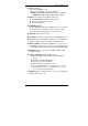
Chapter 2 Installations Connectors on the CI5VGM The connectors on the CI5VGM allows you to connect external devices such as keyboard, floppy disk drives, hard disk drives, printers, etc. The following table lists the connectors on CI5VGM and their respective functions. Connector Locations on the CI5VGM................................25 J1: Floppy Drive Connector ...............................................26 J2: Parallel Port Connector.................................................
Chapter 2 Installations Connector Locations on the CI5VGM CI5VGM User’s Manual 25
Chapter 2 Installations J1: Floppy Drive Connector J1 is a 34-pin header and will support up to 2.88MB floppy drives.
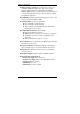
Chapter 2 Installations IDE1, IDE2: EIDE Connectors IDE1 IDE2 IDE1: Primary IDE Connector Signal Name Pin # Pin # Reset IDE 1 2 Host data 7 3 4 Host data 6 5 6 Host data 5 7 8 Host data 4 9 10 Host data 3 11 12 Host data 2 13 14 Host data 1 15 16 Host data 0 17 18 Ground 19 20 DRQ0 21 22 Host IOW 23 24 Host IOR 25 26 IOCHRDY 27 28 DACK0 29 30 IRQ14 31 32 Address 1 33 34 Address 0 35 36 Chip select 0 37 38 Activity 39 40 Signal Name Ground Host data 8 Host data 9 Host data 10 Host data 11 Host data 12 H
Chapter 2 Installations J3: External ATX Power Connector 1 6 J3 Pin # 1 2 3 4 5 6 Signal Name Dual function power button GND Dual function power button GND PS-ON (soft on/off) 5V SB (standby +5V) J18: AT Power Connector J18 Pin # 1 2 3 4 5 6 Signal Name N/A +5V +12V -12V GND GND J4: Audio I/O Connector (optional) J4 28 Signal Name +12V GND Out-L Auxi-L GND Line-L Min Vcc RxD GP7 GP5 GP3 GP1 Pin # 1 3 5 7 9 11 13 15 17 19 21 23 25 Pin # 2 4 6 8 20 12 14 16 18 20 22 24 26 Signal Name -12V Out-R
Chapter 2 Installations J4: Audio I/O Connector (Continued) The J4 Audio I/O Connector connects to the EXTVGM Audio Daughter Card with the 26-pin ribbon cable supplied with the package. The EXTVGM Audio Daughter card provides two CD-AUDIO IN internal connectors and external connectors for LINE OUT, LINE IN, MICROPHONE, and JOYSTICK/MIDI. Refer to the figure below.
Chapter 2 Installations J6: COM1 Serial Port J6 Pin # 1 2 3 4 5 6 7 8 9 10 Signal Name DCD, Data carrier detect RXD, Receive data TXD, Transmit data DTR, Data terminal ready GND, ground DSR, Data set ready RTS, Request to send CTS, Clear to send RI, Ring indicator NC J7: COM2 Serial Port J7, a 10-pin header connector , is the onboard COM2 serial port of the CI5VGM and is configurable as RS-232, RS-422 or RS-485. The following table shows its pin assignments. Pin # .
Chapter 2 Installations J8: Front Bezel Connector The front bezel of the case has a control panel which provides light indication of the computer activities and switches to change the computer status. J8 is a 20-pin header that provides interfaces for the following functions. Hard Disk Drive LED Reset Switch Turbo LED Connector ATX Power On Switch Not Defined Power LED and Keylock Speaker Speaker: Pins 1 - 4 This connector provides an interface to a speaker for audio tone generation.
Chapter 2 Installations ATX Power ON Switch: Pins 7 and 17 This 2-pin connector is an “ATX Power Supply On/Off Switch” on the system that connects to the power switch on the case. When pressed, the power switch will force the system to power on. When pressed again, it will force the system to power off. Turbo LED Connector: Pins 8 and 18 There is no turbo/deturbo function on the CPU card. The Turbo LED on the control panel will always be On when attached to this connector.
Chapter 2 Installations J9: LCD Panel Connector J9 is a dual-in-line header for flat panel LCD displays. The following shows the pin assignments of this connector. 58 57 2 1 Signal Name +12V GND +5V/3.
Chapter 2 Installations J14: Chassis Fan Power Connector J14 is a 3-pin header for the chassis fan. The fan must be a 12V fan. 1 2 3 Pin # 1 2 3 Signal Name Rotation +12V Ground J22, J23: CPU Fan Power Connectors J22 and J23 are pin headers for the CPU fan. The fan must be a 12V fan. 1 2 1 3 2 Pin # 1 2 3 Signal Name Rotation +12V Ground Pin # 1 2 Signal Name +5V Ground J15: IrDA Connector J15 is used for an IrDA connector for wireless communication. +5V IRRX IRTX N.C.
Chapter 2 Installations J17: External Mouse Connector J17 Pin # 1 2 3 4 Signal Name Mouse data Ground 5V Mouse Clock J19: PS/2 Keyboard Connector J19 Pin # 1 2 3 4 5 6 Signal Name Keyboard data N.C. Ground 5V Keyboard clock N.C. J20: PS/2 Mouse Connector J20 CI5VGM User’s Manual Pin # 1 2 3 4 5 6 Signal Name Mouse data N.C. Ground 5V Mouse Clock N.C.
Chapter 2 Installations J21: VGA CRT Connector Signal Name Red Blue GND GND N.C. N.C. HSYNC NC J21 Pin # 1 3 5 7 9 11 13 15 Pin # 2 4 6 8 10 12 14 Signal Name Green N.C. GND GND GND N.C. VSYNC J25: RJ45 Connector This connector is for the 10/100Mbps Ethernet capability of the CPU card The figure below shows the pin out assignments of this connector and its corresponding input jack.
Chapter 2 Installations Watchdog Timer Configuration The function of the watchdog timer is to reset the system automatically and is defined at I/O port 0443H. To enable the watchdog timer and allow the system to reset, write I/O port 0443H. To disable the timer, write I/O port 0441H for the system to stop the watchdog function. The timer has a tolerance of 20% for its intervals. The following describes how the timer should be programmed.
Chapter 3 BIOS Configuration This page was intentionally left blank.
Chapter 3 BIOS Configuration 3 BIOS Configuration This chapter describes the different settings available in the Award BIOS that comes with the CI5VGM CPU card. The topics covered in this chapter are as follows: BIOS Introduction.............................................................. 42 BIOS Setup ........................................................................ 42 Standard CMOS Setup ....................................................... 44 Date .............................................
Chapter 3 BIOS Configuration PCI/VGA Palette Snoop ..........................................49 OS Select for DRAM > 64MB ................................49 HDD S.M.A.R.T. Capability ...................................49 Video BIOS Shadow................................................50 C8000 - CBFFF Shadow/DC000 - DFFFF Shadow 50 Chipset Features Setup .......................................................51 DRAM Timing.........................................................51 SDRAM Cycle Length.......
Chapter 3 BIOS Configuration Load BIOS Defaults........................................................... 59 Load Setup Defaults........................................................... 59 Integrated Peripherals ........................................................ 60 OnChip IDE First/Second Channel.......................... 58 IDE Prefetch Mode.................................................. 60 IDE HDD Block Mode............................................
Chapter 3 BIOS Configuration BIOS Introduction The Award BIOS (Basic Input/Output System) installed in your computer system’s ROM supports Intel Pentium II processors in a standard IBM-AT compatible I/O system. The BIOS provides critical low-level support for standard devices such as disk drives, serial and parallel ports. It also adds virus and password protection as well as special support for detailed fine-tuning of the chipset controlling the entire system.
Chapter 3 BIOS Configuration ROM PCI/ISA BIOS CMOS SETUP UTILITY AWARD SOFTWARE, INC.
Chapter 3 BIOS Configuration Standard CMOS Setup “Standard CMOS Setup” choice allows you to record some basic hardware configurations in your computer system and set the system clock and error handling. If the motherboard is already installed in a working system, you will not need to select this option. You will need to run the Standard CMOS option, however, if you change your system hardware configurations, the onboard battery fails, or the configuration stored in the CMOS memory was lost or damaged.
Chapter 3 BIOS Configuration Time The time format is: Hour : 00 to 23 Minute : 00 to 59 Second : 00 to 59 To set the time, highlight the “Time” field and use the / or +/- keys to set the current time. Primary HDDs / Secondary HDDs The onboard PCI IDE connectors provide Primary and Secondary channels for connecting up to four IDE hard disks or other IDE devices. Each channel can support up to two hard disks; the first is the “Master” and the second is the “Slave”.
Chapter 3 BIOS Configuration NOTE: The specifications of your drive must match with the drive table. The hard disk will not work properly if you enter incorrect information in these fields. If your hard disk drive type is not matched or listed, you can use Type User to define your own drive type manually. Drive A / Drive B These fields identify the types of floppy disk drive A or drive B that has been installed in the computer. The available specifications are: 360KB 1.2MB 720KB 1.44MB 2.88MB 5.25 in. 5.
Chapter 3 BIOS Configuration BIOS Features Setup This section allows you to configure and improve your system and allows you to set up some system features according to your preference. ROM / PCI ISA BIOS BIOS FEATURES SETUP AWARD SOFTWARE, INC.
Chapter 3 BIOS Configuration Quick Power On Self Test When enabled, this field speeds up the Power On Self Test (POST) after the system is turned on. If it is set to Enabled, BIOS will skip some items. Boot Sequence This field determines the drive that the system searches first for an operating system. The options are : A, C, SCSI D, A, SCSI SCSI, C, A C, A, SCSI E, A, SCSI C only C, CDROM, A F, A, SCSI LS/ZIP, C CDROM, C, A SCSI, A, C The default value is A, C, SCSI.
Chapter 3 BIOS Configuration Typematic Rate Setting When disabled, continually holding down a key on your keyboard will generate only one instance. When enabled, you can set the two typematic controls listed next. By default, this field is set to Disabled. Typematic Rate (Chars/Sec) When the typematic rate is enabled, the system registers repeated keystrokes speeds. You can select speed range from 6 to 30 characters per second. By default, this item is set to 6.
Chapter 3 BIOS Configuration Video BIOS Shadow This item allows you to change the Video BIOS location from ROM to RAM. Video Shadow will increase the video speed. C8000 - CBFFF Shadow/DC000 - DFFFF Shadow Shadowing a ROM reduces the memory available between 640KB to 1024KB. These fields determine whether or not optional ROM will be copied to RAM.
Chapter 3 BIOS Configuration Chipset Features Setup This Setup menu controls the configuration of the motherboard chipset. ROM PCI/ISA BIOS CHIPSET FEATURES SETUP AWARD SOFTWARE INC.
Chapter 3 BIOS Configuration Video BIOS Cacheable When enabled, access to video BIOS addressed at C0000H to C7FFFH is cached, provided that the cache controller is disabled. System BIOS Cacheable When enabled, access to the system BIOS ROM addressed at F0000H-FFFFFH is cached, provided that the cache controller is disabled. Memory Hole at 15MB - 16MB In order to improve performance, certain space in memory can be reserved for ISA cards.
Chapter 3 BIOS Configuration USB Keyboard Support The field enables or disables the support for a USB keyboard. CPU Warning Temperature This field sets the threshold temperature at which an alert is sounded through the system’s speaker. The CPU temperature is monitored by the onboard thermal sensor to prevent the CPU from overheating. Temperature/Fan Speed/Voltage The values for the system/CPU temperature, CPU/chassis fan speed and system voltages are displayed as monitored by the H/W monitoring IC.
Chapter 3 BIOS Configuration Power Management Setup The Power Management Setup allows you to save energy of your system effectively. It will shut down the hard disk and turn off video display after a period of inactivity. ROM PCI/ISA BIOS POWER MANAGEMENT SETUP AWARD SOFTWARE, INC.
Chapter 3 BIOS Configuration PM Control by APM This field allows you to use the Advanced Power Management device to enhance the Max. Power Saving mode and stop the CPU’s internal clock. If the Max. Power Saving is not enabled, this will be preset to NO. Video Off Option The Video Off options are Suspend -> Off, Always On, and All Modes -> Off. By default, this field is set to Suspend -> Off. Video Off Method This field defines the Video Off features. There are three options.
Chapter 3 BIOS Configuration Suspend Mode When enabled, and after the set time of system inactivity, all devices except the CPU will be shut off. PM Events The VGA, LPT & COM, HDD & FDD, DMA/master, PWR-ON by Modem/LAN, RTC Alarm Resume, and Primary INTR sections are I/O events which can prevent the system from entering a power saving mode or can awaken the system from such a mode. When an I/O device wants to gain the attention of the operating system, it signals this by causing an IRQ to occur.
Chapter 3 BIOS Configuration PNP/PCI Configuration This option configures the PCI bus system. All PCI bus systems on the system use INT#, thus all installed PCI cards must be set to this value. ROM PCI/ISA BIOS PNP/PCI CONFIGURATION AWARD SOFTWARE INC.
Chapter 3 BIOS Configuration CPU to PCI Write Buffer When enabled, this option increases the efficiency of the PCI bus to and speed up the execution in the processor. By default, this field is set to Enabled. PCI Dynamic Bursting When enabled, this option combines several PCI cycles into one. By default, this field is set to Disabled. PCI Master 0 WS Write When enabled, this option increases the write cycle speed. By default, this field is set to Disabled.
Chapter 3 BIOS Configuration Load BIOS Defaults This option allows you to load the troubleshooting default values permanently stored in the BIOS ROM. These default settings are non-optimal and disable all high-performance features. ROM PCI/ISA BIOS CMOS SETUP UTILITY AWARD SOFTWARE, INC.
Chapter 3 BIOS Configuration Integrated Peripherals This option sets your hard disk configuration, mode and port. ROM PCI/ISA BIOS INTEGRATED PERIPHERALSP AWARD SOFTWARE INC.
Chapter 3 BIOS Configuration IDE Primary/Secondary Master/Slave UDMA These fields allow your system to improve disk I/O throughput to 33Mb/sec with the Ultra DMA/33 feature. The options are Auto and Disabled. Init AGP Display First This field allows the system to initialize first the VGA card in the AGP slot on the motherboard when system is turned on. Onboard Audio Chip Select Enabled to use the integrated audio chip on the motherboard.
Chapter 3 BIOS Configuration Supervisor / User Password These two options set the system password. Supervisor Password sets a password that will be used to protect the system and Setup utility. User Password sets a password that will be used exclusively on the system. To specify a password, highlight the type you want and press . The Enter Password: message prompts on the screen. Type the password, up to eight characters in length, and press .
Chapter 3 BIOS Configuration IDE HDD Auto Detection This option detects the parameters of an IDE hard disk drive, and automatically enters them into the Standard CMOS Setup screen. ROM PCI/ISA BIOS STANDARD CMOS SETUP AWARD SOFTWARE, INC.
Chapter 3 BIOS Configuration Save & Exit Setup This option allows you to determine whether or not to accept the modifications. If you type “Y”, you will quit the setup utility and save all changes into the CMOS memory. If you type “N”, you will return to Setup utility. ROM PCI/ISA BIOS CMOS SETUP UTILITY AWARD SOFTWARE, INC.
Chapter 4 Audio Driver Installation Guide 4 Audio Driver Installation Guide This chapter describes the audio driver installation procedure for the onboard YAMAHA YMF715-S audio chip. The YMF715-S (OPL3-SA3) single audio chip integrates OPL3 and its DAC, 16bit Sigma-delta CODEC, MPU401 MIDI interface, joystick with timer, and a 3D enhanced controller. For normal operations and to maximize the audio functions of the motherboard, follow the audio driver installation procedure below.
Chapter 4 Audio Driver Installation Guide Installing the Audio Drivers for Windows 95 Step 1. After installing Windows 95, insert the CD or audio drivers floppy disk that comes with your motherboard in the CD-ROM or floppy disk drive (labeled YAMAHA Audio YMF715 Windows 95 Drivers). Step 2. Click on Start → Setting → Control Panel→ System → Device Manager. Upon clicking on Other Devices, the figure below appears. Remove OPL3-SAX Sound Board, and then click Refresh.
Chapter 4 Audio Driver Installation Guide Step 3. When the figure below appears, press the Next to search for the driver. Step 4. When the figure below appears, click Other Locations…, then type d:\sound\ya715\win95 or a:\ and click OK.
Chapter 4 Audio Driver Installation Guide Step 5. The Update Device Driver Wizard will find YAMAHA OPL3-SAx Sound System and show the following figure. Click Finish. Step 6. When the Opl3sa.drv on OPL3-SAx driver could not be found, type the driver location as d:\sound\ya715\win95 or a:\ as shown below. Click OK.
Chapter 4 Audio Driver Installation Guide Step 7. When file copying is done and the figure below appears, insert the Windows 95 CD into the CD-ROM, and then click OK. Step 8. When the driver installation is finished, continue to install the YSTATION software. Press Start → Run, then type d:\Sound\YA715\Win95\ystation\setup or a:\ setup (The disk is labeled YAMAHA Audio Application for Windows 95), then press Enter. Refer to the figure below.
Chapter 4 Audio Driver Installation Guide Step 9. When the figure below appears, click Typical, and then continue the installation by following Install Wizard. It is recommended that the default settings assigned by the Install Wizard be applied during the first time installation.
Chapter 4 Audio Driver Installation Guide Setting the 3D Function Step 1. Click Start in the task bar, and then select Settings. Click Control Panel.
Chapter 4 Audio Driver Installation Guide Step 2. Double click the OPL3-SAx Config icon. Step 3. Move Ymersion slide bar to adjust the 3D effects.
Chapter 4 Audio Driver Installation Guide Using YAMAHA Software Wavetable for Windows 95 The audio driver includes the YAMAHA Soft GM software. After finishing the audio driver installation, you can use this software to change some settings for better MIDI sound quality. Step 1. To switch to FM or Soft GM (Software Wavetable) MIDI generator on Windows 95, click Start in the task bar, and then select Settings. Click Control Panel.
Chapter 4 Audio Driver Installation Guide Step 2. In the Control Panel window, double click the Multimedia icon.
Chapter 4 Audio Driver Installation Guide Step 3. When the window below appears, choose the MIDI tab. Three items are shown. These items are: • OPL3-SA FM Synthesizer Select OPL3 FM synthesizer. • OPL3-SA MPU401 Select Hardware Wavetable. • OPL3-SA SoftSynth Select Soft GM (S/W Wavetable). Depending on which device you would like to select, point the mouse cursor to the device name and click it. Then click the OK button. The device is ready to be used.
Chapter 4 Audio Driver Installation Guide Installing the Audio Drivers for Windows NT 4.0 Step 1. Before installing the audio drivers for Windows NT 4.0, you must first install the file pnpisa.inf. This file can be found in the Windows NT 4.0 CD or the Service Pack3 CD. It is recommended that the file in the Service Pack3 CD be used. When the file has been found, select the file by clicking the mouse and then click the mouse right button. Click Install to start copying files into your system.
Chapter 5 VGA Driver Installation Guide 5 VGA Driver Installation Guide This chapter describe the VGA driver installation procedure for the onboard Trident 9520/25. This chapter contains the following sections: Installing Trident 9520/25 Drivers for Windows 95................... 78 Installing Trident 9520/25 Drivers for Windows 98................... 84 Installing Trident 9520/25 Drivers for Windows NT 4.0 ...........
Chapter 5 VGA Driver Installation Guide Installing Trident 9520/25 Drivers for Windows 95 Step 1. In the Windows 95 screen, click Start. Select Settings, then click the Control Panel icon.
Chapter 5 VGA Driver Installation Guide Step 2. Double click Display, then click Settings.
Chapter 5 VGA Driver Installation Guide Step 3. Click Advanced Properties, then click Change....
Chapter 5 VGA Driver Installation Guide Step 4. Click Have Disk .... If "D:" is your CDROM, type D:\VGA\Trid9520\WIN95 and click OK. If you are using the floppy disk labeled Trident 9520/25 VGA Driver Windows 95/98, type A:\ and click OK.
Chapter 5 VGA Driver Installation Guide Step 5. Select Trident Cyber 9520/25 PCI/AGP (VX.XX.XXXX.95), then click OK.
Chapter 5 VGA Driver Installation Guide Step 6. After the files are copied, click Close. Step 7.
Chapter 5 VGA Driver Installation Guide Installing Trident 9520/25 Drivers for Windows 98 Step 1. Click Start. Select Settings, then click the Control Panel icon.
Chapter 5 VGA Driver Installation Guide Step 2. Double click Display.
Chapter 5 VGA Driver Installation Guide Step 3. Click Settings.
Chapter 5 VGA Driver Installation Guide Step 4. Click Advanced.
Chapter 5 VGA Driver Installation Guide Step 5. Click Adapter.
Chapter 5 VGA Driver Installation Guide Step 6. Click Change....
Chapter 5 VGA Driver Installation Guide Step 7. Click Next. Step 8. Select Display a list of all the drivers in a specific location, so you can select the driver you want.
Chapter 5 VGA Driver Installation Guide Step 9. Click Have Disk .... Step 10. If "D:" is your CDROM, type D:\VGA\Trid9520\WIN98, If you are using the floppy disk labeled Trident 9520/25 VGA Driver Windows 95/98, type A:\ and click OK.
Chapter 5 VGA Driver Installation Guide Step 11. Select Trident Cyber 9520/25 PCI/AGP(vx.xx.xxxx.98), then click OK. Step 12. Click Next.
Chapter 5 VGA Driver Installation Guide Step 13. After the files are copied, click Finish.
Chapter 5 VGA Driver Installation Guide Step 12. Click Close.
Chapter 5 VGA Driver Installation Guide Step 13. Click Close. Step 14. Click Yes to restart your computer and for the new settings to take effect.
Chapter 5 VGA Driver Installation Guide Installing Trident 9520/25 Drivers for Windows NT 4.0 IMPORTANT: You should install the Windows NT 4.0 Service Pack 3 first before installing the Trident 9520/25 VGA drivers. If you don't have the Windows NT 4.0 Service Pack 3, please contact your software vendor or download it from Microsoft's web site. Step 1. Boot Windows NT 4.0. Step 2. Double click the My Computer icon. Step 3. Double click the Control Panel icon. Step 4. Double click the Display icon. Step 5.
Chapter 6 System Monitor Utility 6 System Monitor Utility This chapter introduces System Monitor Utility that comes with the motherboard in conjunction with the onboard hardware monitoring IC. The sections in the following pages give the functions of the utility.
Chapter 6 System Monitor Utility System Monitor is a utility software that oversee the general performance of systems, covering areas like system temperature, system voltage, CPU and system fan rotational speeds. If conditions become adversed, that is, when voltages are erratic or CPU temperature exceeds the safe limits, an alarm will be sounded; thereby preventing system crashing and ensuring overall stability. NOTE: System Monitor currently supports English and Chinese under Windows 95/98 and Windows NT.
Chapter 6 System Monitor Utility The following screen appears upon clicking on the System Monitor icon. Clicking on the upper left corner button would show you the latest company information. "Summary" provides the current system status. The section below describes the different functions of System Monitor. 1. Computer - displays the current working system version and processor type.
Chapter 6 System Monitor Utility 2. Power - displays the current voltage status.
Chapter 6 System Monitor Utility 3. Memory - displays the current memory usage status.
Chapter 6 System Monitor Utility 4. Fan Speed - displays the current rotational speeds of CPU and chassis fans. 5. Disk - displays the disk supported formats and disk space.
Chapter 6 System Monitor Utility 6. Heat - displays the CPU and system temperatures. 7. Error Log - displays errors occurring after System Monitor is started.
Chapter 6 System Monitor Utility 8. Setting - sets the values at which an alarm is sounded. Voltage : the acceptable voltage range between the "MAX" and "MIN" value. Temperature : temperature threshold. Fan Rotation Speed : the minimum rotation speed. NOTE: Intel has defined a margin of difference for the voltages as below: 12 Volts - 10% (10.8V ~ 13.2V) 5 Volts - 5% (4.75 ~ 5.25%) Vio - 5% (Vio for P54C CPU is 3.5V. Vio for P55C is 3.3V.
Chapter 7 LANDesk Client Manager 7 LANDesk Client Manager This chapter gives a brief introduction to the optional LANDesk Client Manager (LDCM) utility, as well as the installation procedures. The following items are covered in this chapter: Introduction .............................................................................. 106 Installation ................................................................................ 107 Installing the Local Version of LDCM..........................
Chapter 7 LANDesk Client Manager Introduction LANDesk Client Manager provides the capability for managing components (network interface cards, memory, printers, software applications, etc.) within a PC system. It uses the Desktop Management Interface (DMI) standard established by the Desktop Management Task Force (DMTF). Manageable components can be viewed, monitored, and administrated across multiple platforms, either locally or remotely on a network.
Chapter 7 LANDesk Client Manager Installation The optional LANDesk utility that comes with the CPU card runs in Windows NT or Windows 95 operating system. Upon entering the Windows NT 4.0 or Windows 95 environment, insert the CD. Windows will autorun the installation program and show the following screen. NOTE: During Setup, you will be asked to install Internet Explorer 3.02 in order to continue, or else Setup will be aborted.
Chapter 7 LANDesk Client Manager Installing the Local Version of LDCM Double Click on ‘LANDesk Client Manager’ in the initial screen and the following screen will appear. Double click on the local version of LANDesk Client Manager. When the Welcome screen appears, click on “Next” to continue with Setup.
Chapter 7 LANDesk Client Manager Choose the directory location where Setup will install LANDesk Client Manager. Click “Browse” if you want to change the directory suggested. Otherwise, click “Next” to start installing LDCM. When Setup is finished, changes will have been made to the file AUTOEXEC.BAT. Restart your computer for the changes to take effect.
Chapter 7 LANDesk Client Manager Installing the Administrative Version of LDCM After double clicking on ‘LANDesk Client Manager’ in the initial screen, select the administrative version of the LDCM and the Welcome screen below will appear. Click on “Next” to continue. The screen below allows you to install the documentation in Adobe Acrobat format and the Adobe Acrobat Reader software. Select the options you need and click on “Next” to start the installation.
Chapter 7 LANDesk Client Manager After LANDesk Client Manager Setup is complete, restart your computer to be able to use the LANDesk Client Manager.
Chapter 7 LANDesk Client Manager This page is intentionally left blank.
Chapter 8 Ethernet Setup User’s Guide 8 Ethernet Setup User’s Guide This chapter gives a brief introduction to the Intel 82558 Fast Ethernet PCI controller. The following items are covered in this chapter: Introduction .............................................................................. 114 Features .................................................................................... 114 Software Drivers Support .........................................................
Chapter 8 Ethernet Setup User’s Guide Introduction Intel 82558B is a 32-bit 10/100MBps Ethernet controller for PCI local bus-compliant PCs. It supports the bus mastering architecture, and Auto-negotiation feature which make it possible to combine one common type of Ethernet cabling – an RJ-45 connector for twisted-pair cabling that can be used for both 10Mbps and 100Mbps connection. Extensive driver support for commonly used network operating systems is also provided.
Chapter 8 Ethernet Setup User’s Guide LAN Driver Installation for Windows 95 The CI5VGM comes with a diskette labeled Intel 82558B LAN Windows 95/98 & Windows NT 4.0 Drivers that is to be used in conjunction with the LAN drivers installation. You must use the correct drivers in order for LAN to function properly. Follow the steps below to install the drivers for Windows 95. 1. Click Start ⇒ Select Settings ⇒ Select Control Panel.
Chapter 8 Ethernet Setup User’s Guide 2. Click System. 3. Click Device Manager.
Chapter 8 Ethernet Setup User’s Guide 4. Expand Other Devices. 5. Select PCI Ethernet Controller, then click Properties.
Chapter 8 Ethernet Setup User’s Guide 6. Click Driver. [ 1.
Chapter 8 Ethernet Setup User’s Guide 7. Click Update Driver.
Chapter 8 Ethernet Setup User’s Guide 8. Insert the diskette labeled Intel 82558B LAN Windows 95/98 & Windows NT 4.0 Drivers into the floppy disk drive, then click Next. 9. Click Finish. Ensure the updated driver mentioned is for Intel 82558 Fast Ethernet.
Chapter 8 Ethernet Setup User’s Guide 10. Click OK. 11. Type A:\, then click OK. 12. Click OK.
Chapter 8 Ethernet Setup User’s Guide 13. Type the Computer Name and Workgroup, then click Close. 14. Insert the Windows 95 CD ROM, then click OK.
Chapter 8 Ethernet Setup User’s Guide 15. Type D:\Win95 (Assuming D:\Win95 is the directory location of the Windows 95 files), then click OK. 16. Click Yes to restart the computer and for the settings to take effect.
Chapter 8 Ethernet Setup User’s Guide LAN Driver Installation for Windows NT 4.0 The CI5VGM comes with a diskette labeled Intel 82558B LAN Windows 95/98 & Windows NT 4.0 Drivers that is to be used in conjunction of the LAN drivers installation. Follow the steps below to install the drivers for Windows NT 4.0. 1. Click Start ⇒ Settings ⇒ Control Panel. 2. Click Network. 3. Click Yes. 4. Select Wired to the network, then click Next. 5. Click from the list. 6. Click Have Disk. 7.
Chapter 8 Ethernet Setup User’s Guide Running Diagnostics The CI5VGM comes with a diskette containing the diagnostic software supporting the Intel 82558B Ethernet controller. Follow the steps below to use the Setup Utility. 1. Run the file SETUP.EXE typing a:\setup in the DOS prompt, assuming your floppy disk drive is drive A. Upon doing so, the system starts the Setup Utility and shows the following screen. 8255x-based PCI EtherExpress™ adapter Setup V4.
Chapter 8 Ethernet Setup User’s Guide 3. Selecting Test adapter will show the following screen. 8255x-based PCI EtherExpress™ adapter Setup V4.16 Test adapter Bus=0 Dev=0Bh Slot=11 Addr=004063001000 IRQ=10 Diagnostic tests: Adapter tests ……………………………. Onboard loopback tests ……………….. Network test …………………………… 10Mbps Passed passed passed This adapter works properly Press Enter to continue Help = F1 Press Enter to continue 4. Selecting Install network drivers will show the following screen.
Chapter 8 Ethernet Setup User’s Guide 5. Upon selecting Others under the Install network drivers main menu screen, the following screen will appear. 8255x-based PCI EtherExpress™ adapter Setup V4.16 Other 1. LANtastic 6.0 2. Banyan 6.00 NDIS workstation 3. NDIS 2.x driver notes (OS/2*, LAN Manager* others) 4. Using IBM LAN support for AS/400 and NetWare 5. LAN Server 6. UNIX driver information Choose OTHER if you use a network operating system from a manufacturer not on this list (such as Banyan or UNIX).
Appendix Appendix A. I/O Port Address Map B.
Appendix A. I/O Port Address Map Each peripheral device in the system is assigned a set of I/O port addresses which also becomes the identity of the device. There are a total of 1K port address space available. The following table lists the I/O port addresses used on the Industrial CPU Card.
Appendix B. Interrupt Request Lines (IRQ) There are a total of 15 IRQ lines available on the Industrial CPU Card. Peripheral devices use interrupt request lines to notify CPU for the service required. The following table shows the IRQ used by the devices on the Industrial CPU Card.