ZMAXdp Dual AMD Opteron™ SFF Barebone User’s Manual Version 1.
IWILL ZMAXdp Contents: FCC Compliance Statement ………………………….……………………………………………..........4 Disclaimer, Trademarks and Copyright ………………………….……………………………...............5 Welcome ………………………………………………………….……………………………...............6 About this manual ..…………………………………………………………………….………….............7 About this guide ….…………………………………………………………………….………….............8 Unpacking …….………………………………………………………………….…………......................9 Chapter 1. System Introduction…………………………………………………………………...10 Front Panel Features …….
SFF Workstation Installation Guide Chapter 4. Mainboard Information………………………………………………………………..39 Introduction……………………………………………………………………………………………...…40 Motherboard photos…………………………………………………………………………………...…41 Motherboard layout..…………………………………………………………………………………...…43 Central processing unit and System memory………..……………………………………………...…46 Expansion slot ………………………………………………………………………………...................48 Jumpers Setting …………………………………………………………………………........................50 Internal Connectors………..
IWILL ZMAXdp Federal Communications Commission (FCC) statement This equipment has been tested and found to comply with limits for a Class B digital device, pursuant to Part 15 of the FCC rules. These limits are designed to provide reasonable protection against harmful interference in residential installations. This equipment generates, uses, and can radiate radio frequency energy, and if not installed and used in accordance with the instructions, may cause harmful interference to radio communications.
SFF Workstation Installation Guide Disclaimer The information in this document is subject to change without notice. The manufacturer makes no representations or warranties regarding the contents of this manual and specifically disclaims any implied warranties of merchantability or fitness for any particular purpose.
IWILL ZMAXdp Copyright This publication, including all photographs, illustrations and software, is protected under international copyright laws, with all rights reserved. Neither this manual, nor any of the material contained herein, may be reproduced without the express written consent of the manufacturer.
SFF Workstation Installation Guide Welcome Thank you for buying the IWILL® ZMAXdp barebone! The barebone delivers a host of new features and latest technologies making it another standout in the long line of IWILL quality motherboards! The barebone combines the powers of the AMD Opteron™ processor and the NVIDIA® nForce3 Pro250 chipset to set a new benchmark for an effective desktop platform solution.
IWILL ZMAXdp About this Manual Audience This guide provides general information and installation instructions about the IWILL ZMAXdp series Barebone workstation. This guide is intended for experienced users and integrators with hardware knowledge of personal computers. How this guide is organized This document contains the following parts: 1. Chapter 1: System Introduction This chapter gives a general description of the IWILL barebone system.
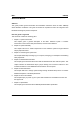
SFF Workstation Installation Guide About this guide Illustrations used in this guide WARNING! Information to prevent injury to yourself when trying to complete a task. DANGER! Information to prevent damage to the components. IMPORTANT Information that you MUST follow to complete a task. NOTE Tips and additional information to aid in completing a task. Where to find more information Refer to the IWILL Websites for additional information and for product and software updates.
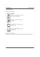
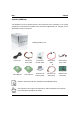
IWILL ZMAXdp Unpacking ZMAXdp Your ZMAXdp may not be supplied with all of the accessories shown, depending on the system configuration you purchased. For details on the accessories supplied with your computer, see the specifications sheet in this manual.
SFF Workstation Installation Guide Chapter 1 All about the IWILL ZMAXdp series barebone system: the front and rear panel features, and the internal layout and design. The IWILL ZMAX series barebone system includes the IWILL motherboard, a power supply, accessories and cables built into in a chassis computer to which you can attach external options, such as external speakers, a printer, or a scanner.
IWILL ZMAXdp ZMAXdp Front Panel Features: The front panel of ZMAXdp features: a 5.25” empty bay, 6-in-1 card reader, two 6-pin Firewire jacks, and two USB2.0 connectors A Open H Empty Bay For Optical Drive B Microphone I Optical Drive Eject Button C Earphone J IEEE1394 (Firewire) D USB2.0 Port K Empty 3.5" FDD or Card Reader E USB2.0 Port L USB2.0 Port F Power On Button M USB2.
SFF Workstation Installation Guide ZMAXdp Rear Panel Features: The back panel of your ZMAXdp contains the ports for supplied and optional accessories. The icons on the back panel locate and identify the ports on your computer.
IWILL ZMAXdp Internal Features The figure below shows the system from side. The standard components (Motherboard, Heatsink for processors, power supply…) are already installed. Actual products may look different from the photo.
SFF Workstation Installation Guide Chapter 2 Step-by-step instructions on how to install basic components. This section outlines how to install and configure your ZMAXdp. various jumpers, connectors, slots, and ports. Then follow these steps designed to guide you through a quick and correct Installation of your system. IWILL has designed the ZMAXdp for an IWILL motherboard only. It is not advisable to install other motherboards.
IWILL ZMAXdp Removing the cover 1. Disconnect all cables attached to the computer. This includes power cords, input/output (I/O) cables, and any other cables that are connected to the computer. 2. Remove the WLAN antenna on the top of the computer 3. Release the three screws at the rear of the left side cover 4. Separate the case and chassis cover: use your thumbs to pull it off, from the front to the back, then lift it off the chassis.
SFF Workstation Installation Guide Lifting the casing cover Separate the case and chassis cover: use your thumbs to pull it off, from the front to the back, then lift it off the chassis. If you remove the side panel immediately after you shut down your computer, the components may be too hot to touch. Wait until the internal parts of the system unit cool down before you attempt to remove the side panel.
IWILL ZMAXdp Turn over the drive holder Release the screws from the CDROM/ HDD rack with a screw driver. Release the screws from the rack Release the two screws holding the rack to the casing. Set one screws aside.. Remove this screw Remove another screw holding the rack to the casing and set it aside. Pull drive holder up Draw the drive holder a little bit. Pull up the holder, fix the rack on the casing and make it steady.
SFF Workstation Installation Guide Remove the drive holder Please remove the drive holder entirely. It would be easier to install graphic card, CPUs and memory. Release the screws from the CDROM/ HDD rack with a screw driver. Release the screw from the rack Release the two screws holding the rack to the casing. Set one screws aside.. Remove this screw Remove another screw holding the rack to the casing and set it aside.
IWILL ZMAXdp Remove the pre-installed heatsink assembly To install the CPU, it is necessary to remove the pre-installed heatsink module. Please remove six screws from heatsink. Gently handle the heatsink module. Avoid hitting, falling or throwing down the heatsink.
SFF Workstation Installation Guide Release the first heatsink entirely Remove the heatsink, and set it aside. Gently handle the heatsink module. Avoid hitting, falling or throwing down the heatsink.
IWILL ZMAXdp Central Processing Unit (CPU) Overview The motherboard comes with a surface mount two 940-pin Zero Insertion Force (ZIF) socket designed for the AMD Opteron™ processors. Gold Triangle on the CPU Take note of the marked corner (with gold triangle) on the CPU. This mark should match a specific corner on the socket to ensure correct installation. 940-pin ZIF socket Locate the two 940-pin ZIF socket on the motherboard. The CPU fits only in one correct orientation.
SFF Workstation Installation Guide Installing the Processor Lever Raised, Unlock the socket Unlock the socket by pressing the lever sideways, then lift it up to a vertical angle. Position the CPU Position the CPU above the socket such that its marked corner matches the base of the socket lever. Gently push down on the processor. Lowering the locking lever Press it firmly on the socket while you push down the socket lever to secure the CPU.
IWILL ZMAXdp Place the heatsink on the processor Never power on unless the heatsink is properly and firmly attached. Apply the Thermal cream After installing the CPU you need to apply the Thermal cream to the top of the installed CPU. Position the CPU Position the CPU above the socket such that its marked corner matches the base of the socket lever. WRONG WAY to Install the Heatsink This illustrator shows the WRONG way to install the heatsink.
SFF Workstation Installation Guide Installing the heatsink and tighten the screws Place the screws and tighten down the heatsink. Do not over-tighten the screws. Ensure that the retention heatsink bases are flat with the motherboard. Secure the each screw one by one and follow the number sequence shown as the illustrator. Note: The bottom of the heatsink is parallel with the motherboard. This is the only proper way to install the heatsink.
IWILL ZMAXdp Installing system memory The barebone comes with four Double Data Rate (DDR) Dual Inline Memory Module (DIMM) sockets. The following figure illustrates the location of the sockets. Memory configurations You may install 64MB, 128MB, 256MB, 512MB, 1GB registered DDR DIMMs into the DIMM sockets using the memory configurations in this section. Important notes on memory configurations 1. Always install DIMMs with the same CAS latency.
SFF Workstation Installation Guide Installing a DIMM Make sure to unplug the power supply before adding or removing DIMMs or other system components. Failure to do so may cause severe damage to both the motherboard and the components. Installing Memory Modules Unlock a DIMM socket by pressing the retaining clips outward. Align the ”notch” on the memory module to the “break” on the socket.
IWILL ZMAXdp Installing an AGP card Accelerated Graphics Port (AGP) slot that supports AGP8X/4X cards. When you buy an AGP card, make sure that you ask for one with +1.5V specification. Put the AGP card directly over the proper slot and press one end of the card into the slot. Firmly press the other end until it is fully seated in the slot. Note the notches on the card golden fingers to ensure that they fit the AGP slot on your ZMAXdp. Install only 1.5V AGP cards on this motherboard! 3.
SFF Workstation Installation Guide Installing hard disk drives ZMAX comes with two available internal bay to hold two standard 3.5-inch hard disk drive. Your system can support ATA-33, ATA-66, or ATA-100 hard disk drives. IWILL recommends using an ATA-100 hard disk drive to take full advantage of your system's features. Slip the HDDs into the bay Carefully slip the HDDs into the disk drive bay. Your new hard disk drive is supplied with the necessary screws.
IWILL ZMAXdp Installing a optical drive ZMAX comes with one available internal bay to hold a standard 5.25-inch optical drive. Your system can support IDE CDROM/ DVD/ DVD+-RW drives. Follow these steps to install a CD/DVD-ROM drive. Slip the CDROM/ DVD into the bay Carefully slip the optical drive into the CDROM bay. Your new CDROM drive is supplied with the necessary screws. Attaching the drive screws Ensure that the four screw holes are properly aligned. Tighten in the screws.
SFF Workstation Installation Guide Chapter 3 The small form factor design of the IWILL barebone system help to maximize work space and compliments your interior design. 1. Positioning the System Unit 2. Setting Up Your Computer 3.
IWILL ZMAXdp Positioning the System Unit The small form factor system is placed on a flat stable surface, like an office desk or computer table.
SFF Workstation Installation Guide Setting Up Your Computer Connecting a Display (Monitor) Plug the display's cable into the monitor port from the VGA card (which been installed). Connecting the Keyboard and Mouse Plug the keyboard cable into the keyboard port on the back of the computer. Plug the mouse cable into the mouse port on the back of the computer.
IWILL ZMAXdp Connecting the Ethernet cable Plug the LAN cable into the LAN jack, located on the back panel of your computer. Plug the other end of the LAN cable into the wall jack. Connecting the printer Plug the USB cord into the back of the computer.
SFF Workstation Installation Guide Connecting the Scanner Plug the USB cord into the back of the computer. Plug both the USB to scanner and scanner’s power cords into a grounded AC wall outlet Connecting the Power Cords Plug the power cord into the back of the computer. Plug both the display and computer power cords into a grounded AC wall outlet or a power strip.
IWILL ZMAXdp Connecting the USB peripherals Plug the USB cord into the front of the computer. Connecting the IEEE1394 digital video camcorder Plug the IEEE1394 cord into the front of the computer.
SFF Workstation Installation Guide Connecting the Speakers Plug the Speaker cord into the rear of the computer by Audio Line Out. 1. Line In jack. This Line In (light blue) jack connects a tape player or other audio sources. In 6-channel mode, the function of this jack becomes Bass/Center. 2. Line Out jack. This Line Out (lime) jack connects a headphone or a speaker. In 4-channel and 6-channel mode, the function of this jack becomes Front Speaker Out. 3. Mic In, Microphone jack.
IWILL ZMAXdp Arranging your workspace Here are some guidelines to help you find better way to use your computer. . Viewing Distance Lower Back Support Seat Height Sitting in the same position for a long time can cause fatigue. A good chair can make a big difference. The backrest and seat should adjust independently and provide good support. The seat should have a curved front to relieve pressure on the thighs.
SFF Workstation Installation Guide Chapter 4 This chapter gives information about the IWILL motherboard that came with the system. This chapter includes the motherboard layout, jumper settings, and connector locations..
IWILL ZMAXdp Introduction The ZMAXdp mainboardis a high-performance motherboard that supports the AMD Opteron™ with 940-pin socket. This board has two DIMM memory sockets that supports maximum 2GB DDR SDRAM and AGP 8X, PCI for future expansion. The board uses the latest nVIDIA® nFORCE 3 PRO 250 MCP to integrate all system control functions.
SFF Workstation Installation Guide ZMAXdp motherboard layout User’s Manual 41
IWILL ZMAXdp Rear External Connectors PS/2 Ports The PS/2 ports are for a system keyboard and mouse or other tracking device. It is recommended that you do not plug or unplug devices when the system is on. Serial Port The COM Serial port has a 9-pin connector and can operate at speeds up to 115,200bps. Do not connect or disconnect a serial port when the system is turned on.
SFF Workstation Installation Guide Ethernet Ports The two LAN Ports are RJ-45 connectors for standard Cat 5 LAN cabling. The connectors attach to the onboard CK8 MAC and MARVELL GbE PHY respectively. USB Ports There are four high-speed USB 2.0 ports, USB 0 and USB 1, for connecting either USB 1.1 or 2.0 devices to the system. It does not matter if the system is on when you connect or disconnect USB devices. See the graphic below.
IWILL ZMAXdp Central Processing Unit and System memory CPU Socket The ZMAXdp supports a two 940-pin AMD Opteron processor. The CPU requires pair heatsink,.
SFF Workstation Installation Guide System Memory Socket This DIMM system memory socket supports DDR 400/333/266 SDRAM system memory modules. Flexible memory technology allows a full spectrum of DDR usage from highest performance to more cost-effective systems.
IWILL ZMAXdp Expansion Slot PCI Slot, The PCI expansion slot on the ZMAX version lets you install additional system hardware via add-on cards. There is one 32-bit, 33MHz slot that is compliant with PCI 2.1/2.2 on this motherboard. AGP Slot, The AGP slot is for the exclusive use of high speed AGP video display cards. This AGP slot supports AGP4X/8X cards. This slot only supports 1.5V devices. Do not use a 3.3V AGP card with this motherboard.
SFF Workstation Installation Guide Mini PCI Slot The mini PCI slot is used to connect wireless LAN card or additional Mini PCI card. Before you installed any card on this board Please unplug the power cord from the wall socket before touching any component. Wear a grounded wrist strap or touch a safely grounded object or to a metal object, such as the power supply, before handling components to avoid damaging them due to static electricity.
IWILL ZMAXdp Jumpers Setting Clear CMOS Jumper This jumper switch clears the RTC RAM CMOS Setup configuration that is stored in the real-time clock’s CMOS memory. If configuration becomes corrupted, or if the CMOS settings are changed to an unsuitable configuration, the motherboard may not work properly. This jumper lets you delete the configuration data stored in CMOS memory and reset the CMOS to the Optimized Defaults. Follow the procedure below to clear CMOS memory. 1.
SFF Workstation Installation Guide Internal Connectors IDE1, IDE2: IDE Drive Connectors The two IDE drive connectors are marked IDE1, the primary channel, and IDE2, the secondary channel. Each connector supports two drives, a Master and a Slave. Pin 20 on each IDE connector is removed to match the covered hole on the UltraDMA cable connector. This prevents incorrect orientation when you connect the cables. For UltraDMA100/66 IDE devices, use an 80-conductor IDE cable.
IWILL ZMAXdp SATA Drive Connectors These SATA connectors support the thin Serial ATA cables for primary internal storage devices. The current Serial ATA interface allows up to 150 MB/s data transfer rate, faster than the standard parallel ATA with 133 MB/s (UltraDMA133). The Serial ATA cable is smaller and more flexible allowing easier routing inside the chassis. The lower pin count of the Serial ATA cable eliminates the problem caused by the wide, flat ribbon of the Parallel ATA interface.
SFF Workstation Installation Guide Power Connectors The two power connectors let you attach two leads from an ATX12V power supply to the motherboard. The board requires a 24-pin ATX connector plus a 8-pin ATX12V connector. Insert the 24-pin lead of the ATX12V power supply into the first 20 holes of the power connector leaving the last four empty. Insert the 8-pin ATX12V lead into the another power connector.
IWILL ZMAXdp this page intentionally left blank 52 User’s Manual
SFF Workstation Installation Guide Chapter 5 This chapter gives information about the ZMAX Basic Input/Output System (BIOS) operation. The ZMAXdp BIOS provides the Power-On Self-Test (POST), the BIOS Setup program, the PCI and IDE auto-configuration utilities. Refer this chapter for more information about the BIOS. The BIOS includes security features that restrict whether the computer. A supervisor password and a user password can be set for the BIOS Setup and for booting the computer.
IWILL ZMAXdp Updating Your BIOS Creating a bootable floppy disk A. DOS environment Insert a 1.44 MB floppy disk into the drive. At the DOS prompt, type: format A:/S then press . B. Microsoft® Windows® environment a. Insert a 1.44 MB floppy disk into the floppy disk drive. b. From your Windows desktop, click on Start, then select My Computer. c. Select the 3 1/2 Floppy Drive icon. d. Click File from the menu, then select Format. A Format 3 1/2 Floppy Disk window appears. e.
SFF Workstation Installation Guide Using “AMIFLASH.EXE” to update the BIOS Update the BIOS using the AMIFLASH.EXE utility in DOS environment. 1. Visit the IWILL website ( http://www.iwill.net ) to download the latest BIOS file for your motherboard. Save the BIOS file to a bootable floppy disk. 2. At the DOS prompt, type the command line: AMIFLASH / where “filename” means the latest (or original) BIOS file that you copied to the bootable floppy disk.
IWILL ZMAXdp BIOS Setup program This chapter discusses the AMI® BIOS Setup program built into the ROM BIOS. The Setup program allows users to modify the basic system configuration. The BIOS is the Basic Input / Output System used in all IBM PC, XT, AT, and PS/2 compatible computers. The AMIBIOS flash chip stores the system parameters, such as type of disk drives, video displays, etc. in the CMOS.
SFF Workstation Installation Guide Using The BIOS Setup Utility Navigating through the BIOS Setup Utility is straightforward. Use the arrow keys to highlight items, press to select items in menus, and press to quit. The following table provides more details about how to navigate in the Setup program using the keyboard.
IWILL ZMAXdp IMPORTANT The BIOS does NOT automatically save values that you have modified. If you do not save your values before you exit the BIOS Setup Utility, all your changes will be lost. If after making and saving system changes with the BIOS Setup Utility, you discover that your computer is no longer able to boot, the AMIBIOS® supports an override, which will reset your system to the Failsafe defaults.
SFF Workstation Installation Guide Main Menu This is the first screen that is displayed when you enter the BIOS Setup Utility. Each tab lined on the top of the screen represents each different menu. The following picture shows the main menu. Main menu shows the information of BIOS version, date and ID; processor type, speed and count; system size. In addition, system time and date is adjustable using + / - key or number keys. BIOS Setup Main Menu Use the arrow keys to select items.
IWILL ZMAXdp Advanced Menu This is the Advanced Menu screen. You can make these modifications on the Advanced Menu. Select the Submenus to modify those settings.
SFF Workstation Feature CPU Configuration IDE Configuration Installation Guide Option GART Error Reporting SuperIO Configuration Description Enable only for testing purpose Enable or Disable IDE Controller Configures devices connected to the Super I/O Configuration Disabled 360 KB, 5 1/2” 1.2 MB, 5 1/2” 720 KB, 3 1/2” 1.44 MB, 3 1/2” 2.88 MB, 3 1/2” Select Floppy A or Floppy B and then selects floppy-diskette type installed in your system.
IWILL ZMAXdp IDE Configuration Submenu You can also setup your PCI IDE controller on Advance menu.
SFF Workstation Installation Guide PCI PnP You can use this screen to view PnP (Plug & Play) BIOS Configuration Menu. This menu allows the user to configure how the BIOS assigns resources & resolves conflicts. Use the up and down arrow ( / ) keys to select an item. Use the Plus and Minus (+/-) keys to change the value of the selected option. The settings are described on the following pages.
IWILL ZMAXdp Feature Option Description Plug & Play O/S Yes No Yes: lets the O/S configure PnP devices not required for boot if your system has a Plug and Play O/S PCI Latency Timer 32, 64, 96, 128, 160, Value in units of PCI clocks for PCI device 192, 224, 248 latency timer register Allocate IRQ to PCI VGA Yes No Yes: Assign IRQ to PCI VGA card if card requests IRQ No: Doesn’t assign IRQ To PCI VGA cars even if card requests IRQ Palette Snooping Disabled Enabled Enabled: informs the PCI devi
SFF Workstation Installation Guide Boot Configurations You can display Boot Setup option by highlighting it using the Arrow (↑/↓) keys and pressing Enter. The settings are described on the following pages. Boot Settings Configuration Sub-Menu Use this screen to select options for the Boot Settings Configuration. Use the up and down arrow (↑/↓) keys to select an item. Use the Plus and Minus (+/-) keys to change the value of the selected option.
IWILL ZMAXdp Feature Option Description Quick Boot Mode Enabled/ This option allows user bypass BIOS self test Disabled during POST Disabled Enable this option to hide BIOS Post messages Enabled during POST Quick Boot Add On Force BIOS Allows user to force BIOS/Option ROM of add on ROM Keep Current cards to be displayed during quiet boot On Choose status of keyboard NUM LOCK key Quiet Boot Display Mode Boot up Number-Lock Off PS/2 Mouse Support Typematic Rate Enabled Allows user t
SFF Workstation Installation Guide BIOS Security Menu The system can be configured so that all users must enter a password every time the system boots or when BIOS Setup is entered, using either the Supervisor password or User password. The Supervisor and User passwords activate two different levels of password security. If you select password support, you are prompted for a one to six character password. Type the password on the keyboard. The password does not appear on the screen when typed.
IWILL ZMAXdp To set a Supervisor Password: 1. Select the Change Supervisor Password item and press Enter. 2. On the password box that appears, you can type a password composed of letters and/or numbers, and press Enter. Your password should have at least six characters. 3. Confirm the password when prompted. The message “Password Installed” appears after you have successfully set your password. 4. The Supervisor Password item now shows Installed.
SFF Workstation Installation Guide BIOS Chipset Configurations There are three submenus inside Chipset menu: NorthBridge Configuration, SouthBridge Configuration and AGP Configuration. This menu allows the user to customize functions of the nVIDIA® nFROCE® MCP Chipsets. North Bridge configuration contains options for Memory & CPU settings. South Bridge configuration contains options for SM Bus & USB. Select a menu by highlighting it using the Arrow ( ↑/↓ ) keys and pressing Enter.
IWILL ZMAXdp North Bridge Chipset Configuration Sub-Menu This menu gives options for customizing memory settings. Select a menu by highlighting it using the Arrow ( ↑/↓ ) keys and pressing Enter. The settings are described on the following pages.
SFF Workstation Installation Guide Memory Configuration Sub-Menu This menu has options for memory speed & latency. Use the up and down arrow ( ↑/↓ ) keys to select an item. Use the Plus and Minus (+/-) keys to change the value of the selected option.
IWILL ZMAXdp South Bridge Chipset Configuration Sub-Menu This menu allows the user to enable SMBus, Audio Codec, MAC Bridge… interface. Use the up and down arrow ( ↑/↓ ) keys to select an item. Use the Plus and Minus (+/-) keys to change the value of the selected option.
SFF Workstation Installation Guide Power Menu Use this screen to select options for power management & ACPI. Use the up and down arrow (↑/ ↓ ) keys to select an item. Use the Plus and Minus (+/-) keys to change the value of the selected option. A description of the selected item appears on the right side of the screen. The settings are described on this page. The screen is shown below.
IWILL ZMAXdp BIOS Exit Menu The Exit menu items allow you to load the optimal or failsafe default values for the BIOS items, and save or discard your changes to the BIOS items. Pressing does not immediately exit this menu. Select one of the options from this menu or from the legend bar to exit. Save Changes and Exit Once you are finished making your selections, choose this option from the Exit menu to ensure the values you selected are saved to the CMOS RAM.
SFF Workstation Installation Guide Load Optimal Defaults This option allows you to load the default values for each of the parameters on the Setup menus. When you select this option or if you press , a confirmation window appears. Select [Yes] to load default values. Select Exit Saving Changes or make other changes before saving the values to the non-volatile RAM. Load Failsafe Defaults Use this option to load all default failsafe setup values.
IWILL ZMAXdp this page intentionally left blank 76 User’s Manual
SFF Workstation Installation Guide Chapter 6 This chapter gives information about the ZMAX Software, drivers, and utilities operation.
IWILL ZMAXdp Drivers and Utilities The ZMAXdp series comes bundled with a Power Installer CD-ROM disc that includes driver and utility software. This chapter describes installing and using this software. Running the Power Installer Disc The Power Installer CD-ROM install interface runs under Microsoft Windows 9X, NT 4.0, 2000, or XP. After inserting the disc into your CD-ROM drive the install interface loads automatically. Choose model ZMAX from the selections.
SFF Workstation Installation Guide Chapter 7 This chapter gives information about the ZMAX detail Hardware Specifications. For more information of IWILL ZMAXdp, visit IWILL website at http://www.iwill.net Products specification and details may change without notice.
IWILL ZMAXdp Specifications Processor System Bus Supports AMD Opteron CPU with 940 PGA Up to 2-way Supports 200 series Opteron Supports 1MB L2 cache Enables simultaneous 32- and 64-bit Computing Scalable Hyper-Transport Bus technology High throughput (6.4GB/sec) Chipset Drive Bay nVIDIA® nForce3 Professional MCP TI® IEEE1394 TSB43AB22PDT Host Controller Marvell® 88E1111 PHY Native nVIDIA® Ethernet MAC One 5.25" internal drive bay for optical driver Two 3.
SFF Workstation Installation Guide IEEE-1394 Power Supply IEEE1394-1394A compliant OHCI compatible interface One IEEE1394 ports on the front panel; 100/200/400 Mbps data transfer rates 300 Watt power supply with fully support ATX specification NVRAID™ Weight Provides support for RAID 0, RAID 1 8.