EDR1600 16 CHANNEL D I G I TA L V I D E O R E C O R D E R INSTRUCTION MANUAL Before installing and using this unit, please read this manual carefully. Be sure to keep the manual handy for later reference.
Administrator’s Guide and Operating Instructions WARNING TO REDUCE RISK OF FIRE OR ELECTRIC SHOCK, DO NOT EXPOSE THIS APPLIANCE TO RAIN OR MOISTURE. CAUTION DO NOT REMOVE COVER. NO USER SERVICEABLE PARTS INSIDE. REFER SERVICING TO QUALIFIED SERVICE PERSONNEL. WARNING: This equipment has been tested and found to comply with the limits for a Class “A” digital device, pursuant to part 15 of the FCC Rules.
Administrator’s Guide and Operating Instructions PRECAUTIONS Refer all work related to the installation of this product to qualified service personnel or system installers. Do not block the ventilation opening or slots on the cover. Do not drop metallic parts through slots. This could permanently damage the appliance. Turn the power off immediately and contact qualified service personnel for service. Do not attempt to disassemble the appliance. To prevent electric shock, do not remove screws or covers.
Administrator’s Guide and Operating Instructions Table of Contents 1. Product Overview………………….……………………….……... 1.1 Features…………………..……….…………..…………………... 1.2 Technical Overview…….….…….………………………….…….. 2. Front & Rear Panels….…….……………………………….……. 3. System Installation…….…….……………………………….…… 3.1 Before Installation…….……….…………………………….……. 3.2 Basic Connections…………….…………………………….…….. 3.3 Optional Connections…………..…………………………….…… 4. Main Screen…………………………………………..……….…... 5. Basic Operations & Log Display……………………..………..
Administrator’s Guide and Operating Instructions 1. Product Overview The PowerPlex EDR1600 is a state-of-the-art digital video recorder that brings unparalleled price/performance video surveillance, recording and playback to the CCTV systems. With parallel processing architecture, high performance video engine, and intelligent recording algorithms, triplex operation can be easily achieved without sacrificing the increasing demands of performance, reliability, and availability in the CCTV industry. 1.
Administrator’s Guide and Operating Instructions 1.2 Technical Overview 1.2.1 Video Input and Output The digital video recorder is designed to support either NTSC/EIA or PAL/CCIR standard. To make the auto detection of video standard work, at least one camera must be connected to the video input. The product features video camera inputs with a passive looping output for each. Camera input impedance termination is set independently for each camera automatically.
Administrator’s Guide and Operating Instructions disk, ZIP disk, etc. in .MPG format for MPEG-1 encoded video or .MOV format for JPEG encoded video. For Time-Lapse Mode Recording Time, please refer to Appendix B. 1.2.4 Motion Detection The digital video recorder continuously monitors all camera inputs for motion.
Administrator’s Guide and Operating Instructions 1.2.7 Expandable IDE Hard Disk Architecture All the other HDD-based digital video recorders support only 1-4 hard disks. If those recorders do support more hard disks, they usually use RAID (Redundant Arrays of Independent Disks) or SCSI disks, which are very expensive. With the Expandable IDE Hard Disk Architecture, the EDR1600 can support up to 18 pieces of IDE hard disks that are hot swappable.
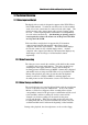
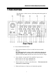
Administrator’s Guide and Operating Instructions 2. Front & Rear Panels The following is a brief overview of the front panel and rear panel of EDR1600. Rear Panel 0. Power Switch From Rear Panel 1. Power Selector Switch: 115V AC or 230V AC selector switch. Warning: To avoid damaging the system, set this switch before plugging in the power plug. Use a screwdriver to set the switch to the correct position so that the number shown is the same as the local AC voltage. 2. 3.
Administrator’s Guide and Operating Instructions 5. USB Connector: Reserved. 6. RS-232 Connector: Com 1, connects to modem. 7. Printer Port Connector: Connects to printer port devices (e.g. ZIP/printer port). 8. RS-232 Connector: Com 2, connects to PTZ camera. 9. External Hard Disk Connector: Connects to External Hard Disk Array EDA800. 10. Main Monitor S-video Output (optional). 11. VGA Monitor Output. 12. Camera 16 Video Input: BNC connector for Camera 16. 13.
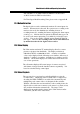
Administrator’s Guide and Operating Instructions Front Panel 25. Hard Disk Trays: Hard disk holders for HDD#1 (upper tray) and HDD#2 (lower tray). Note: Please make sure to set HDD#1 as master and HDD#2 as slave. The settings should be described on the hard disk itself or in the manual come with the hard disk. 26. Floppy Drive: 3.5”, 1.44MB. 27. LEDs, Reset Button and Power Switch: LEDs for power and HDD indication, Reset Button to reset the system, and Power Switch to power on/off the system. 28.
Administrator’s Guide and Operating Instructions 3. System Installation The installations described below should be made by qualified service personnel or system installers. 3.1 Before Installation Please make sure to set the Power Selector Switch before plugging in the power plug to avoid damaging the EDR1600. Use a screwdriver to set the switch to the correct position so that the number shown is the same as the local AC voltage. Please refer to the following diagram for the system connections.
Administrator’s Guide and Operating Instructions 3.2 Basic Connections Cameras Connect each of the camera video input connector to the video output from a camera or other composite video source. At least one camera must be connected before the system is running for the auto detection of video standard to take effect. VGA Monitor Connect the VGA monitor output connector to a VGA monitor. The VGA monitor displays selected live or recorded cameras in any available format.
Administrator’s Guide and Operating Instructions Keyboard Connect the Keyboard Connector to a standard AT keyboard. ZIP / Printer Port If the user wants to use ZIP/Printer Port to retrieve important recorded images, it must be connected to the Printer Port Connector at system startup. EDA800 Connect the External Hard Disk Connector to EDA800 if the user has purchased EDA800. If EDR1600 is running, please power on EDA800 first, and then make the connection.
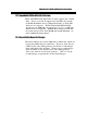
Administrator’s Guide and Operating Instructions 4. Main Screen The diagram above is the main screen display. The icons on the lower corner of the screen are mainly for control and configuration, those on the right corner for status indication. If any icon is grayed, it means that the specific function is not accessible in the current mode or login right. The followings are a brief description for each of the icons. System time in military hour format.
Administrator’s Guide and Operating Instructions Alarm Event Log – To view the event log. Config – To configure (setup) the behaviors of the system. TV Overscan/Underscan – To change the display size of the Main TV Monitor. Login – To login the system as Administrator, Supervisor or Operator. Sequence Mode / Static Page Mode – To toggle between Sequence Mode and Static Page Mode. In Sequence Mode, each page in the designated sequence will be shown for its preset dwelling time sequentially.
Administrator’s Guide and Operating Instructions There are 4 kinds of devices in the status indication. The displaying order is Camera, Alarm Output, Hard Disk, Alarm Input, then back to Camera. Each status bar stands for the status of one device, the bottommost for ID#1. There are 5 different colors: GRAY/BLACK – Not existent or not installed, GREEN – Normal, YELLOW – Video Loss detected for Camera, Alarm for Alarm Input/Output, and Recording for Hard Disk, and RED – Motion detected for Camera. 5.
Administrator’s Guide and Operating Instructions There are 4 kinds of event logs: Alarm, Motion, Video Loss, and Power On/Off. To view the event Log display, please click on the Log icon. The screen will be shown as below: If you logged in as Administrator, the Delete button and Delete All button will be enabled. Click on the Delete button to delete the highlighted event log, and click on the Delete All button to delete all the event logs. 5.
Administrator’s Guide and Operating Instructions 6. Setup (Administrator) To login as an Administrator, please click on the Login icon, and enter the appropriate Administrator’s Login name and Password (the factory default value for both of them is admin). To setup the behaviors of the system, please click on the Config icon. The configuration menu will pop up as below. Click on the menu item for the respective configuration. For the details of each item, please refer to the following paragraphs.
Administrator’s Guide and Operating Instructions 6.1 Time Type Setup The behavior for the system is the same when it’s in the same time Type (or Time Mode). Please refer to Camera Setup and Motion Setup for how they depend on Time Type. There are 2 default Time Types, On duty and Off duty, in the system. However, you may configure up to 16 Time Types to suit your needs. Use the meaningful names no matter they are from human viewpoint or the system’s viewpoint.
Administrator’s Guide and Operating Instructions 6.2 Day Type Setup The daily behaviors for the system are the same for those days configured as of the same Day Type. There are 2 default Day Types, WORK DAY (Monday through Friday) and HOLIDAY (Saturday and Sunday), in the system. However, you may configure up to 16 Day Types to suit your needs. For each Day Type, you may configure up to 16 time segments and their corresponding Time Types, beginning time and end time.
Administrator’s Guide and Operating Instructions 6.3 Calendar Setup The Calendar setup is provided for the administrator to set the Day Type of each calendar day. It’s designed to be a Perpetual Calendar. However, up to 10 years of calendar days can be configured at any specific time. Operations: After the Calendar menu item is selected, the Calendar Setup dialog box will be shown on the screen. The active month is shown on the upper corner of the screen.
Administrator’s Guide and Operating Instructions 6.4 Alarm Action Setup The Alarm Actions allow the administrator to define how the digital video recorder responds to the triggered alarm from the Alarm Inputs. There are up to 16 Alarm Actions that correspond to 16 (Focus) Cameras for most applications. For each Alarm Action, you may configure its behaviors as shown on the screen and described below.
Administrator’s Guide and Operating Instructions Focus Camera – To define the camera that will respond to this Alarm Action. The default settings are Camera 1 for Alarm Action 1, Camera 2 for Alarm Action 2, and so on. Pre-record – Pre-record time to define how long (in seconds) before the Alarm Action is triggered the Focus Camera shall be intensively recorded (Note 2). Use the Up/Down arrow buttons to adjust the value (0-10 seconds).
Administrator’s Guide and Operating Instructions Call Display – If it is checked, the Call Monitor will switch to the Focus Camera when the Alarm Action is triggered. Otherwise, the Call Monitor will switch among all the installed cameras as usual. Log – Log to event log list or not. Please refer to Log Display for the details. Show Message – To display the alarm message or not when the Alarm Action is triggered.
Administrator’s Guide and Operating Instructions 6.5 Motion Action Setup The Motion Actions allow the administrator to define how the digital video recorder responds to the detected motion for the cameras. There are up to 8 Motion Actions that correspond to 8 Alarm Outputs for most applications. The Focus Camera is always the camera with the detected motion. For each Motion Action, you may configure its behaviors as shown on the screen and described below.
Administrator’s Guide and Operating Instructions 6.6 Video Loss Action Setup The Video Loss Actions allow the administrator to define how the digital video recorder responds to the detected video loss for the cameras. There are up to 8 Video Loss Actions that correspond to 8 Alarm Outputs for most applications. The Focus Camera is always the camera with the detected video Loss. For each Video Loss Action, you may configure its behaviors as shown on the screen and described below.
Administrator’s Guide and Operating Instructions 6.7 Hard Disks Full Action Setup The Hard Disks Full Actions allow the administrator to define how the digital video recorder responds when the hard disk drives reach the maximum storage capacity. Operations: After the HDDs Full Action menu item is selected, the HDDs Full Action Setup dialog box will be shown on the screen.
Administrator’s Guide and Operating Instructions Alarm Out – To define which Alarm Output will be triggered when the hard disk capacity is full. NC and NO signals are available, please refer to Alarm Out Setup. Click on the Down arrow button to select one of the Alarm Outputs (AO 1-8). Output – Alarm Out output state when the hard disk capacity is full. For NC signal, it’s always open, for NO signal close. The Normal State above shows whether the selected Alarm Out is NC signal or NO signal.
Administrator’s Guide and Operating Instructions 6.8 Camera Setup The Camera Setup allows the administrator to define the behaviors for each Camera at each Time Type. There are up to 16 Cameras connected to the system. For each Camera and each Time Type, you may configure the behaviors as shown on the screen and described below. Operations: After the Camera menu item is selected, the Camera Setup dialog box will be shown on the screen.
Administrator’s Guide and Operating Instructions Recording Quality For All Cameras – The range is 0-10, with 0 the lowest (rough) quality, 10 the highest (fine) quality. The default value is 5 . Use the Up/Down arrow buttons to adjust the value. Compression Method For All Cameras – MPEG (MPEG-1) or JPEG-CIF (JPEG), resolution – 352x240 for NTSC, 352x288 for PAL. Enable Digital Watermark – Check to enable digital watermark. The system provides up to 64 positions to locate the digital watermark.
Administrator’s Guide and Operating Instructions 6.9 Alarm In Setup The Alarm In Setup allows the administrator to define the behaviors for each Alarm Input at each Time Type. There are up to 24 Alarm Inputs connected to the system. For each Alarm Input and each Time Type, you may enable/disable and select its corresponding Alarm Action. For most applications, 16 Alarm Inputs are enough to correspond to 16 Alarm Actions and hence 16 (Focus) Cameras. 8 more Alarm Inputs are reserved for users’ convenience.
Administrator’s Guide and Operating Instructions Normal State – NC or NO, please check the signal types connected to the Alarm Input Terminal on the rear panel of the system. Use the Down arrow button to select the signal type. Enable Alarm Action – Check to Enable Alarm Action for the selected Alarm Input at the selected Time Type. Alarm Action – The corresponding Alarm Action if the Alarm Input changes its state from normal to alarm. Up to 16 Alarm Actions are selectable.
Administrator’s Guide and Operating Instructions 6.10 Alarm Out Setup The Alarm Out Setup allows the administrator to define the tag name for each Alarm Output. There are up to 4 Normally Closed (NC) signals (AO 1-4) and 4 Normally Open (NO) signals (AO 5-8) for the system. Operations: After the Alarm Out menu item is selected, the Alarm Out Setup dialog box will be shown on the screen.
Administrator’s Guide and Operating Instructions 6.11 Display Sequence Setup The Display Sequence Setup allows the administrator to define the Sequence Mode display. Please refer to Chapter 4 for Sequence Mode display. For the definition of the Display Pages in each Display Sequence, please refer to Display Page Setup. Operations: After the Display Seqs menu item is selected, the Display Sequence Setup dialog box will be shown on the screen. The following is a brief description for each item shown above.
Administrator’s Guide and Operating Instructions 6.12 Display Page Setup The Display Page Setup allows the administrator to define the Display Pages in Sequence Mode display and Static Page Mode display (please refer to Chapter 4). Operations: After the Display Pages menu item is selected, the Display Page Setup dialog box will be shown on the screen. Please select Sequence Mode or Static Page Mode first.
Administrator’s Guide and Operating Instructions Static Page Mode – To set the Display Pages for Static Page Mode display. Sequence No – To select the Sequence Number in Sequence Mode display. Use the Down arrow button to select the number. Page No - To select the Page Number for the selected Sequence Number in Sequence Mode display. Use the Down arrow button to select the number. Page Dwell Time – The Dwell Time (in seconds) for the selected Page shown in Page No.
Administrator’s Guide and Operating Instructions 6.13 Motion Setup The Motion Setup allows the administrator to configure how motion detection works for each Camera at each Time Type. For each Camera and each Time Type, you may configure the Detection Area (16x12 grids) and Sensitivity as shown on the screen and described below. Operations: After the Motion menu item is selected, the Motion Setup dialog box will be shown on the screen. Please select the Camera and the Time Type first.
Administrator’s Guide and Operating Instructions Camera – Use the Down arrow button to select the camera. Time Type - Use the Down arrow button to select the Time Type. Set – To set the Detection Area – active at down position. Clear – To clear the Detection Area – active at down position. Video Window – Showing the images for the selected Camera. Dragging the mouse inside to set (clear) the Detection Area. The motion detection is enabled for the area with net on it.
Administrator’s Guide and Operating Instructions 6.14 Password Setup The Password Setup allows the administrator to set the new Login names and Passwords for the Administrator, Supervisor and Operator. The default (Login, Password) for the Administrator is (admin, admin), the Supervisor (Supervisor, Supervisor), the Operator (operator, operator). Operations: After the Set Password menu item is selected, the Password Setup dialog box will be shown on the screen.
Administrator’s Guide and Operating Instructions 6.15 System Configurations The System Configurations Setup allows the administrator to set up the communication, main monitor sharpness-adjusting, daylight saving time, TV system and backup the configurations to floppy diskette or restore the configurations from the backup floppy diskette. Operations: After the System menu item is selected, the System Configurations dialog box will be shown on the screen.
Administrator’s Guide and Operating Instructions Gateway IP address – Enter the corresponding IP address while the gateway is enabled. - Dial In Configuration Modem – Click on the Detail button to define the Local and Remote IP address. Login Name/Password – Enter the desired Login Name and Password for Dial In function. - Web Server Address – Select the proper Web Server Address by clicking on the desired item. Daylight Saving Time – Check the Enable box to enable Daylight Saving Time.
Administrator’s Guide and Operating Instructions and then select one of the options from Download to floppy or Upload from floppy. To revert all the configuration setting to default value, click on the Factory Setting bottom. Main Monitor Sharpness – The slider bar is for adjusting the sharpness of the images shown on the main monitor screen. To set the sharpness, click on the slider and drag the mouse, to left is for sharper images, to right is for less sharp ones. Note : The V 2.
Administrator’s Guide and Operating Instructions 7. Date/Time Setup (Administrator) If you are an Administrator, please click one the Time displaying on the Main Screen to enter the Date/Time Setup for the system. The date is in YYYY/MM/DD format, whilst the time in military hour format (HH:MM:SS). The built-in real time clock will be updated accordingly.
Administrator’s Guide and Operating Instructions 8. Image Playback and Archive (Administrator, Supervisor) On the Main Screen, please click on the Playback Panel icon, the screen will be shown as below: The icons on the lower corner of the screen are changed to the icons for video playback and archive, those on the right corner not changed (for status indication). The icons remained the same as in the Main Screen provide the same functions as described in Chapter 4.
Administrator’s Guide and Operating Instructions Select HDD & Range – To select the playback Hard Disk and the playback range in that Hard Disk. Click on it, and the Select HDD & Range dialog box will be shown on the screen as described in the next paragraph. Play Saved Video – To preview the retrieved images in the floppy disk, ZIP disk (PC format), etc. Stop – To stop playing the video. If the user plays the video again, it will start from the beginning. Play – To play the selected video.
Administrator’s Guide and Operating Instructions Archive Video – Toggle button to enable/disable retrieving playback video to floppy disk, ZIP disk, etc. When the video is playing back and Archive is enabled (button at DOWN position), the Retrieval Device and Camera dialog box will be shown, please follow the instructions to retrieve the video. (Note.2,3) Replay – To repeat playing the selected video over and over again when the button is at DOWN position.
Administrator’s Guide and Operating Instructions 8.1 Select HDD & Range Dialog Box When the user click on the Select HDD & Range icon on the Playback Panel, the Select HDD & Range dialog box will be shown on the screen. The system provides user to search the image either by HDD location or by time. Use the Down arrow of the upper left column in the diagram box to select the desired searching way. To search by location, the diagram will be shown as below.
Administrator’s Guide and Operating Instructions Options to Play – To playback all recorded video images, or to playback only motion or alarm detected video images of the assigned location. Start/End Section No – 32 MB/Section or 32 Slices/Section for the system. Use the Down arrow button to select the Start/End Section No. Start/End Slice No – 1 MB/Slice for the system. Use the Down arrow button to select the Start/End Slice No.
Administrator’s Guide and Operating Instructions To search by time, the diagram will be shown as below. 01-01-01 2001/8/13 Mon, 18:46:50 Search by Time V 01 08 10 10 10 50 N Y N N N Y Y N N N Y Y N N N N N Y N N N Y Y N N N Y Y N N N N N Y N N N Y Y N N N Y Y N N N N N Y N N N Y Y N Use the Down arrow to select the desired start date and time, click on the Submit button to start searching. The other items are the same as the above description.
Administrator’s Guide and Operating Instructions 9. Remote Control Through Local Network, Intranet, Internet or dial-in functions, users are able to view the live video, image playback and upload/download the configuration file of EDR 1600 from any PC in anywhere. The remote computer does not need to have the EDR1600 software or any special hardware and software installed. Connecting the Remote PC and Server Before you start, please verify the connection between EDR1600 and the , modem or network.
Administrator’s Guide and Operating Instructions time shown on each window refers to the time on EDR1600 system clock. The following is the brief description of each item above. Upper Panel Upload – To upload the configuration files to EDR1600. After the configuration file is uploaded, you must reboot the EDR1600 system. button at the lower panel to reboot the EDR1600 Click on the system from the remote PC. Download – To download the configuration files from EDR1600.
Administrator’s Guide and Operating Instructions – Slider Bar – selected playback cameras will be played and displayed on its corresponding video window. To pause the playback image. Showing the current playing position for image playback. Click on it and drag the mouse to play the video from anywhere in the selected range. Note. 1 The best viewer’s environment is Internet Explorer 5.0 or above, 1024 x 768 If the PC is protected by the Firewall, please make sure Port 1600 is enabled before accessed.
Administrator’s Guide and Operating Instructions New model for 60FPS(NTSC) / 50FPS(PAL) recording rate The V1.20 (and later version) software can support 60FPS(NTSC) / 50FPS(PAL) recording rate on a high-end EDR1600 model. The new model has a “2x/fps” label on its front panel. Please contact your supplier for the new model. Note 1: For the new model, 30FPS(NTSC)/25FPS(PAL) is allocated to odd-numbered (1, 3, 5, .., 15) cameras, and the other 30/25FPS to even-numbered (2, 4, 6, .., 16) cameras.
Administrator’s Guide and Operating Instructions HDD#2 if the former “thinks” the later is absent!) We strongly recommend that you use IBM’s hard disks as HDD#1 (master) because they are very consistent and stable for hot-swap. Note 2: If it happens that HDD#2 is not accessible, please power off both HDD#1 and HDD#2, and then power on both of them immediately. Hard disks in EDA800 If you are using EDA800, please choose IBM’s hard disks for your recording purposes.
Administrator’s Guide and Operating Instructions Video Format Video Input Video Output Main Monitor NTSC/EIA or PAL/CCIR, auto-sensing 16 camera inputs with loop through (BNC), 1Vp-p/75ohm Call Monitor Video Compression Video Resolution 1 D-SUB 15-pin computer monitor output 1 BNC composite video output, 1Vp-p/75ohm (option) 1 mini-din S-video output, 1Vp-p/75ohm (option) 1 BNC composite video output, 1Vp-p/75ohm JPEG and MPEG-1 I Frame 352x240 (NTSC) or 352x288 (PAL) Video Display Display Resolution V
Administrator’s Guide and Operating Instructions Weight Operating Temperature 20KG 0oC ~ +45oC 53
Administrator’s Guide and Operating Instructions Appendix B – Time Lapse Mode Recording Time EDR1600 Time Lapse Mode Recording Time (system storage: 20GB) (Estimated with typical image - low noise level) JPEG Normal (5) day hour min. 20 52 1 17 45 2 14 38 4 8 24 8 16 48 13 1 12 21 17 59 26 2 23 43 11 59 86 23 58 130 11 59 217 11 55 260 23 54 Total Capture Rate (FPS) NTSC PAL 30 25 15 12.5 10 8.3 6 5 3 2.5 2 1.7 1.2 1 1 0.83 0.6 0.5 0.3 0.25 0.2 0.17 0.12 0.1 0.1 Fine (10) day hour min.
Administrator’s Guide and Operating Instructions EDR1600 Time Lapse Mode Recording Time (system storage: 20GB) (Estimated with typical image - low noise level) Total Capture Rate (FPS) NTSC PAL 30 25 15 12.5 10 8.3 6 5 3 2.5 2 1.7 1.2 1 1 0.83 0.6 0.5 0.3 0.25 0.2 0.17 0.12 0.1 0.1 day 1 3 5 9 11 18 37 56 94 113 Fine (5) hour 9 18 27 21 19 16 11 9 22 23 23 23 22 min. 53 14 21 35 10 45 55 30 49 39 28 7 56 MPEG-1 Normal (3) day hour min.
Administrator’s Guide and Operating Instructions Appendix C – Simulated Keyboard There are situations that the user will be asked to enter a numeric or alphanumeric string. So, a Simulated Keyboard is designed for the user to use the mouse for all the operations. Please refer to the following diagram for the details. Appendix D – Q & A Q: The mouse doesn’t work. A: The mouse must be connected to the system at system startup.
Administrator’s Guide and Operating Instructions Q: How to setup time-lapse recording? A: Please setup the Normal Recording rates for the Cameras at different Time Types. The normal recording rates are also time-lapse recording rates. Q: How to setup event recording? A: Please setup the Alarm Recording rates for the Cameras at different Time Types, the different Actions, and the enable/disable items for the Cameras and the Alarm Inputs. The alarm recording rates are also event-recording rates.
www.ness.com.au Head Office: Ness Security Products Pty Ltd ABN 28 069 984 372 Ph +61 2 8825 9222 Fax +61 2 9674 2520 ness@ness.com.au NSW Ph 02 8825 9222 Fax 02 9674 2520 sales@ness.com.au VIC Ph 03 9875 6400 Fax 03 9875 6422 nessmelb@ness.com.au QLD Ph 07 3399 4910 Fax 07 3217 9711 nessbris@ness.com.au WA Ph 08 9328 2511 Fax 08 9227 7073 nessper@ness.com.au SA Ph 08 8152 0000 Fax 08 8152 0100 adelaide@ness.com.au Copyright Notice All rights reserved.