ThinkServer User Guide Machine Types: 0387, 0388, 0389, 0390, 0391, 0392, 0393, and 0441
Note: Before using the information and the product it supports, be sure to read and understand the following: • The Read Me First that comes with your product • “Safety information” on page iii • Appendix A “Notices” on page 179 First Edition (June 2011) © Copyright Lenovo 2011. LIMITED AND RESTRICTED RIGHTS NOTICE: If data or software is delivered pursuant a General Services Administration “GSA” contract, use, reproduction, or disclosure is subject to restrictions set forth in Contract No.
Contents Safety information . . . . . . . . . . iii Chapter 1. General information . . . . . 1 Introduction . . . . . . . . . . . . . . . . . Server documentation . . . . . . . . . . . . . 1 2 Chapter 2. Server setup road map . . . 5 Chapter 3. Product overview . . . . . . 7 Server package . . . . . . . . . . . . . Features . . . . . . . . . . . . . . . . Specifications . . . . . . . . . . . . . . Software . . . . . . . . . . . . . . . . ThinkServer EasyStartup . . . . . . . .
Replacing the hot-swap hard disk drive backplane. . . . . . . . . . . . . . . Replacing the non-hot-swap power supply assembly . . . . . . . . . . . . . . . Replacing a hot-swap redundant power supply module . . . . . . . . . . . . . Replacing the power distribution board and cage assembly . . . . . . . . . . . . . Replacing the front panel board assembly . . Replacing the front system fan . . . . . . Replacing the rear system fan . . . . . . . Replacing the heat sink and fan assembly . .
Safety information Note: Before using the product, be sure to read and understand the multilingual safety instructions on the documentation DVD that comes with the product. Antes de usar o produto, leia e entenda as instruções de segurança multilíngues no DVD de documentação que o acompanha. Преди да използвате този продукт, задължително прочетете и вникнете в многоезичните инструкции за безопасност в DVD диска с документация, който се предоставя с продукта.
Przed skorzystaniem z produktu należy zapoznać się z wielojęzycznymi instrukcjami bezpieczeństwa znajdującymi się na płycie DVD z dokumentacją dostarczoną wraz z produktem. Antes de utilizar o produto, leia atentamente as instruções de segurança multilingues que constam no DVD de documentação fornecido com o produto. Înainte de a utiliza produsul, asiguraţi-vă că aţi citit şi înţeles instrucţiunile de siguranţă în mai multe limbi de pe DVD-ul cu documentaţie care însoţeşte produsul.
Statement 1 DANGER Electrical current from power, telephone, and communication cables is hazardous. To avoid a shock hazard: • Do not connect or disconnect any cables or perform installation, maintenance, or reconfiguration of this product during an electrical storm. • Connect all power cords to a properly wired and grounded electrical outlet. • Connect to properly wired outlets any equipment that will be attached to this product. • When possible, use one hand only to connect or disconnect signal cables.
Statement 3 CAUTION: When laser products (such as CD-ROMs, DVD drives, fiber optic devices, or transmitters) are installed, note the following: • Do not remove the covers. Removing the covers of the laser product could result in exposure to hazardous laser radiation. There are no serviceable parts inside the device. • Use of controls or adjustments or performance of procedures other than those specified herein might result in hazardous radiation exposure.
Statement 6 CAUTION: If you install a strain-relief bracket option over the end of the power cord that is connected to the device, you must connect the other end of the power cord to an easily accessible power source. Statement 7 CAUTION: If the device has doors, be sure to remove or secure the doors before moving or lifting the device to avoid personal injury. The doors will not support the weight of the device.
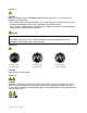
Statement 11 CAUTION: The following label indicates a hot surface nearby. Statement 12 DANGER Overloading a branch circuit is potentially a fire hazard and a shock hazard under certain conditions. To avoid these hazards, ensure that your system electrical requirements do not exceed branch circuit protection requirements. Refer to the information that is provided with your device for electrical specifications.
Statement 16 CAUTION: To reduce the risk of electric shock or energy hazards: • This equipment must be installed by trained service personnel in a restricted-access location, as defined by the NEC and the latest edition of IEC 60950, The Standard for Safety of Information Technology Equipment. • Connect the equipment to a reliably grounded safety extra low voltage (SELV) source.
Statement 20 CAUTION: The battery is a lithium ion battery. To avoid possible explosion, do not burn the battery. Exchange it only with the Lenovo-approved part. Recycle or discard the battery as instructed by local regulations.
Chapter 1. General information This chapter provides some general information about your product. This chapter contains the following items: • “Introduction” on page 1 • “Server documentation” on page 2 Introduction This user guide for your Lenovo® ThinkServer® product contains information about the server features, specifications, component locations, configuration instructions, hardware replacement procedures, and basic troubleshooting and diagnostics.
Record information about your server in the following table. You will need the information if you ever need to have your server serviced. For where to find the product information label on the chassis, see “Machine type, model, and serial number label” on page 13.
documentation DVD might change without notice after the first release of the DVD. You can always obtain all the most up-to-date documentation for your server from the Lenovo Web site at: http://www.lenovo.com/ThinkServerUserGuides The following documents are on the documentation DVD that comes with your server: • Safety Information This is a multilingual document that includes all the safety statements for your product in more than 30 languages.
4 ThinkServer User Guide
Chapter 2. Server setup road map This chapter provides a general road map to guide you through setting up your server. The server setup procedure varies depending on the configuration of the server when it was delivered. In some cases, the server is fully configured and you just need to connect the server to the network and an ac power source, and then you can turn on the server.
6 ThinkServer User Guide
Chapter 3. Product overview This chapter provides information about the server package, features, specifications, software programs, and component locations. This chapter contains the following items: • “Server package” on page 7 • “Features” on page 7 • “Specifications” on page 12 • “Software” on page 12 • “Locations” on page 13 Server package The server package includes the server, power cord(s), printed documentation, documentation DVD, and software media. Figure 1.
Microprocessor Your server comes with one of the following microprocessors (internal cache size varies by model): • Intel® Xeon® quad-core microprocessor • Intel Xeon dual-core microprocessor • Intel Core™ i3 microprocessor For a list of the ThinkServer microprocessor options, go to http://www.lenovo.com/thinkserver. Click the Products tab and then click Options ➙ ThinkServer Processors to view the information.
Internal drives Internal drives are devices that your server uses to read and store data. The internal drives supported by your server vary by model. • Hard disk drive – Five to eight 3.5-inch hot-swap Serial Advanced Technology Attachment (SATA) or Serial Attached SCSI (SAS) hard disk drives (SCSI is the acronym for Small Computer System Interface) – Up to eight 2.5-inch hot-swap SAS hard disk drives – Up to four 3.5-inch hot-swap SATA or SAS hard disk drives – Up to four 3.
Reliability, availability, and serviceability Reliability, availability, and serviceability (hereinafter referred to as RAS) are three important server design features. The RAS features help you to ensure the integrity of the data stored on the server, the availability of the server when you need it, and the ease with which you can diagnose and correct problems.
– Preboot Execution Environment (PXE) The Intel PXE technology enables you to boot your computers, load an operating system, or deploy executable images from a remote server by using a network interface. The operation can be done independently of local data storage devices (such as hard disk drives) or installed operating systems.
– Embedded Web server The BMC provides an embedded Web server for out-of-band management. The user authentication is handled by IPMI user names and passwords. For more information, refer to the Remote Management Module User Guide on the documentation DVD that comes with your server. Specifications This topic lists the physical specifications for your server. Dimensions Width: 195 mm (7.68 inches) Height: 430 mm (16.93 inches) without foot stands; 445 mm (17.52 inches) with foot stands Depth: 595 mm (23.
ThinkServer EasyUpdate Firmware Updater The ThinkServer EasyUpdate Firmware Updater program (hereinafter referred to as Firmware Updater) enables you to maintain your server firmware up-to-date and helps you avoid unnecessary server outages. The Firmware Updater program is provided on the Lenovo Support Web site. For more information about downloading and using the Firmware Updater program, see “Updating the firmware” on page 81.
The following illustration is a sample of the machine type, model, and serial number labels on the server. Note: Depending on the model type, your server might look slightly different from the illustration in this topic. Figure 2.
Front view of the server This topic provides information to help you locate the parts on the front of the server. The following illustration shows the front view of the server. 2 1 U CP ME M U PS Figure 3.
3 Optical drive bay 1 Your server comes with an optical drive installed in the 5.25-inch optical drive bay 1. 4 Optical drive eject/close button Press this button to eject or close the optical drive when the server power is on. 5 Optical drive status LED The optical drive status LED is blinking in green when the optical drive is working or in the POST process. 6 Front door 7 Front door lock You can lock the front door to protect the hard disk drive cages from unauthorized access.
Front panel This topic provides information to help you locate the control, connectors, and LEDs on the front panel of the server. The following illustration shows the control, connectors, and LEDs on the front panel of the server. Depending on the model, your server might look slightly different from the following illustration. Figure 4.
2 Power status LED Color Description On Green The server is on. Off None The server is off. Blinking Green The server is in ACPI S1 mode, which is also known as Power On Suspend (POS) mode. In this mode, the microprocessor is not working while other hardware devices are still working. Hard disk drive status LED The hard disk drive status LED helps you to determine the status of the hard disk drive activity.
Note: The DIT module is only available in some models. The following illustration shows the location of the DIT module and the diagnostic LEDs on the DIT panel in the front of the server. Depending on the model, your server might look slightly different from the following illustration. Figure 5.
The following illustration shows the rear view of the server with a screw-secured, non-hot-swap power supply. Figure 6.
For server models that have hot-swap redundant power supply module(s), there might be one or two power cord connectors 1 on the rear of the server. For each hot-swap redundant power supply module, there might be one or two status LEDs on the power supply module near the power cord connector. When the green LED is lit, it indicates that the hot-swap redundant power supply module is working properly. When the red LED is lit, it indicates that the hot-swap redundant power supply module has failed. Figure 7.
6 7 Ethernet connectors Used to attach an Ethernet cable for a LAN. Each Ethernet connector has two status LEDs to help you identify the Ethernet connectivity, activity, and connection speed. Note: The Ethernet connector 2 (callout 7 ) marked with “MGMT” is for system management. If you want to use remote management functions, you need to connect an Ethernet cable to the Ethernet connector 2. Ethernet status LED 1 Left 2 Right 8 Color Status Description Green On The server is connected to a LAN.
Padlock Your server comes with a padlock loop so that the server cover cannot be removed when a padlock is installed. Figure 8. Padlock Chapter 3.
Integrated cable lock An integrated cable lock, sometimes referred to as the Kensington lock, can be used to secure your server to a non-permanent fixture. The cable lock attaches to the integrated cable lock slot at the rear of your server and is operated with a key. The cable lock also locks the server cover. This is the same type of lock used with many notebook computers. You can order an integrated cable lock directly from Lenovo by searching for Kensington at: http://www.lenovo.com/support Figure 9.
Front door lock You can remove the key attached on the server and use it to open or lock the front door of the server. The front door helps protect the hard disk drive cages to prevent unauthorized access to the installed hard disk drives. Figure 10. Front door lock Server components This topic provides information to help you locate the components of your server. To remove the server cover and gain access to the inside of the server, see “Removing the server cover” on page 85.
The following illustration shows the components of the server with five to eight 3.5-inch hot-swap hard disk drives. Figure 11. Components of the server with five to eight 3.
• There is a 3.5-inch hot-swap hard disk drive or a dummy hard disk drive tray installed in each hard disk drive bay ( 5 to 12 ). Note: The number of the installed hard disk drives varies by model. For the vacant drive bay, there is a dummy hard disk drive tray to cover the place. • For information about the supported expansion card, see “System board components” on page 42.
The following illustration shows the components of the server with up to eight 2.5-inch hot-swap SAS hard disk drives. Figure 12. Components of the server with up to eight 2.
Note: The number of the installed hard disk drives varies by model. For the vacant drive bay, there is a dummy hard disk drive tray to cover the place. • For information about the supported expansion card, see “System board components” on page 42. • Depending on the model, your server might come with a screw-secured, non-hot-swap power supply or hot-swap redundant power supply module(s). • For more information about the memory modules, see “Memory module installation rules” on page 90.
Note: The DIT module 1 is only available in some models and the DIT panel also varies by model. See “DIT module” on page 18. • There is a 3.5-inch hot-swap hard disk drive or a dummy hard disk drive tray installed in each hard disk drive bay ( 5 to 8 ). Note: The number of the installed hard disk drives varies by model. For the vacant drive bay, there is a dummy hard disk drive tray to cover the place. • For information about the supported expansion card, see “System board components” on page 42.
The following illustration shows the components of the server with up to four 3.5-inch non-hot-swap hard disk drives. Figure 14. Components of the server with up to four 3.
• Depending on the model, your server might come with a screw-secured, non-hot-swap power supply or hot-swap redundant power supply module(s). • For more information about the memory modules, see “Memory module installation rules” on page 90. Hot-swap hard disk drive status LEDs This topic applies only to server models with hot-swap hard disk drives. Note: Depending on the model, your server might look slightly different from the illustrations in this topic.
Figure 16. 2.5-inch hot-swap hard disk drive status LEDs 1 Hard disk drive activity LED 2 Hard disk drive RAID status LED Description Off Off The hard disk drive has failed or is not present. On, green Off The hard disk drive is present but not in use. Blinking, green Off The hard disk drive is active and data is being transferred. On, green Blinking rapidly (about four flashes per second), amber The RAID controller is identifying the hard disk drive.
Some server models come with a required RAID card to provide advanced SATA/SAS hardware RAID functions to the server. You can also purchase the RAID card from Lenovo and install it into models that support the RAID card to get advanced SATA/SAS hardware RAID functions. See “Installing or removing the RAID card” on page 98. Note: For server models with more than four hard disk drives or models that use SAS hard disk drives, there must be a RAID card installed.
• Up to eight 2.5-inch hot-swap SAS hard disk drives with one backplane The following illustration shows the locations of the hot-swap hard disk drive backplanes. You need to open the server cover and remove the front system fans to access the backplanes. See “Removing the server cover” on page 85 and “Replacing the front system fan” on page 149. Notes: 1. Depending on the model, your server might look slightly different from the illustration in this topic. 2.
The following illustrations show the connectors on a 3.5-inch hot-swap hard disk drive backplane. Figure 19. Front view of the 3.5-inch hot-swap hard disk drive backplane 1 Slot 0 for a 3.5-inch SATA or SAS hot-swap hard disk drive 3 Slot 2 for a 3.5-inch SATA or SAS hot-swap hard disk drive 2 Slot 1 for a 3.5-inch SATA or SAS hot-swap hard disk drive 4 Slot 3 for a 3.5-inch SATA or SAS hot-swap hard disk drive Figure 20. Rear view of the 3.
Backplane for 2.5-inch hot-swap hard disk drives This topic provides information to help you locate the connectors on the 2.5-inch hot-swap hard disk drive backplane. The following illustrations show the connectors on the 2.5-inch hot-swap hard disk drive backplane. Figure 21. Front view of the 2.5-inch hot-swap hard disk drive backplane 1 Slot 0 for a 2.5-inch SAS hot-swap hard disk drive 5 Slot 4 for a 2.5-inch SAS hot-swap hard disk drive 2 Slot 1 for a 2.
2 Mini-SAS signal cable connector 2 Used to connect the mini-SAS connector on one end of the mini-SAS signal cable. 3 Mini-SAS signal cable connector 1 Used to connect the mini-SAS connector on one end of the mini-SAS signal cable. Connecting cables This topic provides instructions on how to connect the mini-SAS signal cable(s) to the hot-swap hard disk drive backplane(s) and the system board or the required RAID card if you have one installed.
Use the following instructions to connect the cables: 1. Use one 700 mm (27.56 inches) mini-SAS to mini-SAS signal cable. Connect the mini-SAS connector 1 to the port 0 on the RAID card. Then, connect the mini-SAS connector 2 to the mini-SAS signal cable connector on the 3.5-inch hot-swap hard disk drive backplane installed on the lower hard disk drive cage. 2. Use the other 700 mm (27.56 inches) mini-SAS to mini-SAS signal cable. Connect the mini-SAS connector 5 to the port 1 on the RAID card.
Use the following instructions to connect the cables: 1. Use one 700 mm (27.56 inches) mini-SAS to mini-SAS signal cable. Connect the mini-SAS connector 1 to the port 0 on the RAID card. Then, connect the mini-SAS connector 2 to the mini-SAS signal cable connector 1 on the 2.5-inch hot-swap hard disk drive backplane. 2. If you have more than four 2.5-inch hard disk drives installed, use the other 700 mm (27.56 inches) mini-SAS to mini-SAS signal cable.
If you are connecting the SATA hard disk drives to the system board, use the 450 mm (17.72 inches) mini-SAS signal cable with four SATA ports and one Serial General Purpose Input/Output (SGPIO) port. Connect the mini-SAS connector 1 to the mini-SAS signal cable connector on the 3.5-inch hot-swap hard disk drive backplane and connect the four SATA ports 3 – 6 to the SATA connector 0 to SATA connector 3 on the system board. Then, connect the SGPIO port 2 to the SATA SGPIO connector on the system board.
To connect the cables, do the following: 1. Use the 700 mm (27.56 inches) mini-SAS to mini-SAS signal cable. Connect the mini-SAS connector 1 to the port 0 on the RAID card. Then, connect the mini-SAS connector 2 to the mini-SAS signal cable connector on the 3.5-inch hot-swap hard disk drive backplane. 2. Use the 2-pin 200 mm (7.87 inches) RAID card to system board hard disk drive LED cable.
Figure 27. System board components 1 Power Management Bus (PMBus) connector 20 Internal USB 2.0 Type A connector 2 TPM connector 21 Internal dual-port USB 2.0 connector 2 3 Memory slot 4 (DIMMB2) 22 Internal dual-port USB 2.
1 PMBus connector The BMC can read the power supply status registered through PMBus. You do not need to connect any device to the PMBus connector. This connector is kept for power management in models with redundant power supply modules. The function of the PMBus connector is not available for models with a screw-secured non-hot-swap power supply. 2 TPM connector Used to connect a TPM module, which is a security chip, to protect your server and strengthen server security.
19 iKVM key connector Used to connect an iKVM key option, which is a kind of remote management module, to enable the iKVM function on your server. See “Installing or removing the ThinkServer iKVM Remote Management Module” on page 105. 20 Internal USB 2.0 Type A connector Used to connect a device that uses a USB 2.0 Type A connector. 21 Internal dual-port USB 2.0 connector 2 Used to connect the USB cable of the RDX USB drive bundle (server option). 22 Internal dual-port USB 2.
31 PCI Express x4 card slot (PCI-E slot 2) This is a PCI Express x4 lane in physical PCI 2.0 x8 slot that supports a PCI Express x4 card with 167 mm (6.57 inches) in length, such as an Ethernet card. 32 BMC chip With the integrated BMC chip, no matter what condition the server operating system is in and no matter if the server is on or off, as long as the server is connected to network and an ac power source, the interaction with the BMC controlled servers can be achieved through system network.
The following illustration shows a jumper in the default setting position (pin 1 and pin 2). This is the correct position for normal operation. Figure 28. Default jumper setting Chapter 3.
The following illustration shows the status of the jumpers on the system board of your server. You can configure, recover, enable, or disable some specific features of the system board by setting the jumpers. Figure 29. System board jumpers 1 Clear CMOS (Complementary Metal Oxide Semiconductor) /Recovery jumper 4 Clear password jumper 2 BMC setting jumper 5 Manufacturing jumper (reserved for the manufacturer) 3 BIOS recovery jumper Attention: To set the jumpers, you need to open the server cover.
3. Lay the server on its side for easier operation. 4. Locate the Clear CMOS /Recovery jumper on the system board and then move the jumper from the default normal position (pin 1 and pin 2) to the short-circuited position (pin 2 and pin 3). 5. Wait more than 10 seconds and then move the Clear CMOS /Recovery jumper back to the normal position (pin 1 and pin 2). 6. Reinstall the server cover and connect the power cord(s). See “Completing the parts replacement” on page 162. 7. Wait about 30 seconds.
System board LEDs This topic helps you locate the LEDs on the system board. The following illustration shows the BMC status LED, system board hardware fault LED, and the POST code diagnostic LEDs on the system board. Figure 30.
2 BMC status LED This LED indicates the BMC status of your server. 3 Description BMC status LED Color On Green The BMC is not ready. Off None The BMC has no power or fails. Blinking Green The BMC is working. - 10 POST code diagnostic LEDs During the system boot process, the BIOS executes several platform configuration processes, each of which is assigned a specific hex POST code number.
52 ThinkServer User Guide
Chapter 4. Turning on and turning off the server This chapter provides information about turning on and turning off the server. Turning on the server The server can be turned on in one of the following ways: • After you finish unpacking and setting up the server, connect it to an ac power source. Press the power switch on the front panel to turn on the server. See “Front panel” on page 17. The server needs about 30 seconds for the BMC to initialize whenever you connect the server to an ac power source.
2. For information about your specific operating system, refer to the related documentation or help system for the operating system.
Chapter 5. Configuring the server This chapter provides the following information to help you configure the server: • “Using the Setup Utility program” on page 55 • “Using the ThinkServer EasyStartup program” on page 69 • “Configuring RAID” on page 71 • “Configuring the Ethernet controllers” on page 81 • “Updating the firmware” on page 81 Using the Setup Utility program This topic provides information about using the Setup Utility program. The Setup Utility program is part of the server firmware.
• On the Server Management menu, select System Information to view the information about your system, including the BMC information. Setup Utility program interface This topic provides information about the menus and items in the Setup Utility program. Depending on the version of your system BIOS, some menu or item information might differ slightly from the information in this topic. The information in this topic is based on the 0.9b version of the BIOS. Notes: 1.
The following illustration shows an example of the Main menu in the Setup Utility program. Figure 31. An example of the Main menu in the Setup Utility program To set the system date and time on the Main menu, see “Setting the system date and time” on page 64. Advanced menu This topic provides information about the various configuration menus and items on the Advanced menu in the Setup Utility program. You can view or change various server component settings on the Advanced menu.
Menu item Submenu item Intel EIST Technology Selections • Disabled • Enabled P-State Coordination • HW_ALL • SW_ALL Comments Enable or disable the Intel EIST Technology. Change the P-State Coordination type. • SW_ANY Intel Turbo Boost Technology • Disabled C1E Support • Disabled • Enabled • Enabled CPU C3 Report • Disabled • ACPI C2 Enable or disable the Intel Turbo Boost Technology. Enable or disable the C1E Support. Enable or disable the CPU C3 report.
Menu item Submenu item Selections • Power on Comments If the power is interrupted when the server is on, after the power resumes: • If you have selected Stay off, the server will stay in the off state. • If you have selected Last State, the server will resume to the last state. • If you have selected Power on, the server will restart automatically.
Menu item Submenu item Onboard LAN2 I/O ROM Selections • Disabled • Enabled PCI ROM Priority • Legacy ROM • EFI Compatible ROM USB Configuration (set USB configuration parameters) USB Controller • Disabled • Enabled Legacy USB Support • Enabled • Disabled • Auto Port 60/64 Emulation • Disabled • Enabled TANDBERGRDX 3040 • Auto • Floppy • Forced FDD • Hard Disk • CD-ROM Console Redirection Configuration (set console redirection configuration parameters) Console Redirection • Disabled • Serial
Security menu items Menu item Selections Comments Set Administrator Password Set an administrator password to protect against unauthorized access to your server. See “Using passwords” on page 65. Set User Password Set a user password to protect against unauthorized access to your server. See “Using passwords” on page 65. This item is only available after you have set an administrator password.
Server Management menu items Menu item Submenu item Selections View the information about your system, including the BMC version information. System Information BMC LAN Configuration Comments Clear all Event Logs • Enabled • Disabled Configuration Source • Static • Dynamic • Do Nothing If this item is set to Enabled, the SEL will be cleared. Select to configure LAN channel1 parameters statically or dynamically (DHCP).
Menu item Boot Option #1 Selections • UEFI Device Comments Set the first startup device. • Hard Disk Drive • Optical Disk Drive • Removable Device • Network Device Boot Option #2 • UEFI Device Set the second startup device. • Hard Disk Drive • Optical Disk Drive • Removable Device • Network Device Boot Option #3 • UEFI Device Set the third startup device. • Hard Disk Drive • Optical Disk Drive • Removable Device • Network Device Boot Option #4 • UEFI Device Set the fourth startup device.
Menu item Selections Bootup Num-Lock Comments Turn the Num-Lock key on or off. • On • Off • Disabled POST Error Pause Enable or disable the POST error pause feature. When this feature is set to Enabled, the system will stop on the POST screen if any error occurs during the POST. • Enabled Boot Manager menu This topic provides information about the Boot Manager menu in the Setup Utility program.
Using passwords By using the Setup Utility program, you can set a password to prevent unauthorized access to your server. You do not have to set a password to use your server. However, using a password improves computing security. If you decide to set a password, read the following topics.
3. See “Password considerations” on page 65. Then, follow the instructions on the screen to set or change a password. 4. If you want to delete a password, type your current password. Press Enter when you are prompted to type a new password. Then, press Enter to confirm the new password. The previous password will be cleared. Note: If you delete an administrator password, the user password will also be deleted. For security reasons, it is recommended that you always set a password for your server. 5.
3. Press F10 to save settings and exit the Setup Utility program. The server will follow the startup device sequence you have set each time you turn on the server. Exiting the Setup Utility program After you finish viewing or changing settings, press Esc to return to the Setup Utility program main interface. If you are on a nested submenu, press Esc repeatedly until you reach the main interface.
2. Click Download & Drivers ➙ ThinkServer. 3. Find the product name and click the machine type of your server. To find the machine type information on the chassis, see “Machine type, model, and serial number label” on page 13. 4. Locate the BIOS update utility on the Web page and then click the version number of the BIOS update utility program. Follow the instructions on the Web page to download the ISO image or update package and the installation instructions in a TXT file. 5.
1. Download a BIOS update utility program and its installation instructions from the Lenovo Support Web site. Then, make a bootable disc or a bootable USB key and print the TXT file that contains the installation instructions. See “Downloading the BIOS update utility program” on page 67. 2. Remove all media from the drives and turn off all attached devices and the server. Then, disconnect all power cords from electrical outlets and disconnect all cables that are connected to the server. 3.
5. Click the version number of the ThinkServer EasyStartup program and then follow the instructions on the Web page to download the ISO image and installation instructions in a TXT file. Note: The Web page for downloading the ThinkServer EasyStartup program also contains detailed information about the program, including limitations and lists of hints and tips. 6. Use any DVD burning software to create a bootable disc with the ISO image. 7.
• Continue to the main interface. • Install the operating system using a pre-existing response file. • Configure RAID using a pre-existing response file. Read the explanations on the screen and select a desired option. Then, follow the instructions on the screen. If this is the first time you are using the ThinkServer EasyStartup program, select the option to continue to the main interface and view the compatibility notes and user guide. Notes: 1.
• “Configuring RAID using the ThinkServer EasyStartup program” on page 74 • “Configuring the onboard SATA software RAID” on page 75 • “Configuring the advanced SATA or SAS hardware RAID” on page 80 About RAID RAID, an acronym for Redundant Array of Independent Disks, is a technology that provides increased storage functions and reliability through redundancy.
• RAID 10: a combination of RAID 0 and RAID 1 RAID 10 consists of striped data across mirrored spans. A RAID 10 drive group is a spanned drive group that creates a striped set from a series of mirrored drives. RAID 10 allows a maximum of eight spans. You must use an even number of drives in each RAID virtual drive in the span. The RAID 1 virtual drives must have the same stripe size. RAID 10 provides high data throughput and complete data redundancy but uses a larger number of spans.
• Advanced SATA/SAS hardware RAID configuration using the WebBIOS Configuration Utility program; and RAID management using the MegaRAID Storage Manager program and the MegaCLI Configuration Utility program (requires a RAID card) Some server models come with a required RAID card to provide advanced SATA/SAS hardware RAID functions to the server. You can also purchase the RAID card from Lenovo and install it into server models that support the RAID card to get advanced SATA/SAS hardware RAID functions.
Configuring the onboard SATA software RAID The onboard SATA software RAID controller is integrated in the Intel C202 chip on the system board. If your server has SATA hard disk drives that are connected to the system board, you can use the LSI Software RAID Configuration Utility program to configure RAID independently of the operating system. Your server supports onboard SATA software RAID levels 0, 1, and 10. You can also activate RAID 5 by installing a ThinkServer SATA Software RAID 5 activation key.
After entering the LSI Software RAID Configuration Utility program, you can see the Management Menu on the screen. The Management Menu contains the following menu items: • Configure This menu contains items to help you create a RAID array, view the current RAID configuration, add a new array, delete an existing array, or select a boot virtual drive. • Initialize This menu helps you initialize virtual drive(s). Note: Initializing a virtual drive erases all data on the virtual drive.
Creating, adding, or deleting a RAID array This topic provides instructions on how to create, add, or delete a RAID array using the LSI Software RAID Configuration Utility program. Note: Before you create a RAID array using the LSI Software RAID Configuration Utility program, make sure that the server meets the required hardware configuration. For example, the server needs to have the required number of SATA hard disk drives installed and connected to the system board.
1. Start the LSI Software RAID Configuration Utility program. See “Starting the LSI Software RAID Configuration Utility program” on page 75. 2. On the main interface of the program, select Initialize and follow the instructions on the screen. Setting a hot-spare drive This topic provides instructions on how to set a physical drive as a hot-spare drive using the LSI Software RAID Configuration Utility program. A hot-spare drive is an extra, unused drive that is part of the disk subsystem.
be configured between 0 percent and 100 percent. At 0 percent, the rebuild is done only if the system is not doing anything else. At 100 percent, the rebuild has a higher priority than any other system activity. To configure the rebuild rate using the LSI Software RAID Configuration Utility program, do the following: Note: Using a rebuild rate of 0 or 100 percent is not recommended. The default value is 30 percent. 1. Start the LSI Software RAID Configuration Utility program.
Installing and using the MegaRAID Storage Manager program You can install and use the MegaRAID Storage Manager program to manage the RAID array and RAID controller in an operating system environment after configuring RAID. The installation package for the MegaRAID Storage Manager program is on the ThinkServer EasyStartup DVD. After you enter the operating system, insert the ThinkServer EasyStartup DVD into the optical drive.
Configuring the Ethernet controllers The Ethernet controllers are integrated on the system board. They provide an interface for connecting to a 10 Mbps, 100 Mbps, or 1000 Mbps network and provide full-duplex (FDX) capability, which enables simultaneous transmission and reception of data on the network. You do not have to set any jumpers or configure the Ethernet controllers. However, you must install a device driver to enable the operating system to address the controllers.
Notes: 1. Before distributing the firmware updates to a server, ensure that your server can restart successfully without encountering hardware problems. 2. If you have updated the BIOS firmware, all the BIOS settings become the default settings of the updated BIOS version. You need to check and reconfigure the BIOS settings for your specific needs.
Chapter 6. Installing, removing, or replacing hardware This chapter provides instructions on how to install, remove, or replace hardware for your server. This chapter contains the following items: • “Guidelines” on page 83 • “Removing the server cover” on page 85 • “Removing and reinstalling the front bezel” on page 87 • “Installing, removing, or replacing hardware” on page 89 • “Completing the parts replacement” on page 162 For a list of the ThinkServer options, go to http://www.lenovo.
• Make sure that you have an adequate number of properly grounded electrical outlets for the server, monitor, and other devices. • Back up all important data before you make changes to drives. • Have a small flat-blade screwdriver available. • You do not have to turn off the server to install or replace a hot-swap redundant power supply module, hot-swap hard disk drives, or hot-plug USB devices.
• Properly route the cables. For some options, such as PCI cards, follow the cabling instructions that come with the options in addition to the instructions in this manual. • Make sure that you replace a failing fan within 48 hours. • When replacing a hot-swap drive, install the new hot-swap drive within two minutes of removal.
5. Loosen the thumbscrew that secures the server cover and then slide the server cover to the rear until it is stopped. Notes: a. The server cover is securely installed and you need to use a tool, such as a screwdriver, to loosen the thumbscrew that secures the server cover. The thumbscrew is an integrated part of the server cover and do not try to remove the thumbscrew from the server cover. b. It is recommended that you wait three to five minutes to let the server cool before removing the server cover.
6. Pivot the server cover outward to completely remove it. Figure 33. Removing the server cover Attention: For proper cooling and airflow, install the server cover before turning on the server. Operating the server for more than 30 minutes with the server cover removed might damage server components. To reinstall the server cover, see “Reinstalling the server cover and reconnecting cables” on page 162.
3. Remove the front bezel by releasing the three plastic tabs on the left side and pivoting the front bezel outward. Figure 34.
4. To reinstall the front bezel, align the other three plastic tabs on the right side of the front bezel with the corresponding holes in the chassis, then pivot the front bezel inward until it snaps into position on the left side. Figure 35. Installing the front bezel 5. Go to “Completing the parts replacement” on page 162. Installing, removing, or replacing hardware This topic provides instructions on how to install, remove, or replace hardware for your server.
Memory module installation rules Your server has four memory slots for installing or replacing DDR3 UDIMMs with ECC technology. • Supports 2 GB and 4 GB 1333 MHz DDR3 UDIMMs • Single-rank or dual-rank • Minimum system memory: 2 GB (only one 2 GB memory module installed in the DIMMA2 slot) • Maximum system memory: 16 GB (one 4 GB memory module installed in each of the four memory slots) The following illustration helps you to locate the memory slots on the system board. Figure 36.
Installing a memory module Attention: Do not open your server or attempt any repair before reading and understanding the “Safety information” on page iii and “Guidelines” on page 83. This topic provides instructions on how to install a memory module. Before you begin, print all the related instructions or ensure that you can view the PDF version on another computer for reference. Notes: 1.
8. Position the new memory module over the memory slot. Make sure that the notch 1 on the new memory module is aligned with the key 2 in the memory slot. Then, press the new memory module straight down into the memory slot until the retaining clips close and the new memory module snaps into position. Note: If there is a gap between the memory module and the retaining clips, the memory module has not been correctly installed.
6. Locate the appropriate memory module that you want to remove and open the retaining clips on both ends of the memory slot. Then, grasp the memory module by its edges and carefully pull it straight up to remove it from the memory slot. Figure 39. Removing a memory module 7. If you are instructed to return the old memory module, follow all packaging instructions and use any packaging materials that are supplied to you for shipping.
1. Remove all media from the drives and turn off all attached devices and the server. Then, disconnect all power cords from electrical outlets and disconnect all cables that are connected to the server. 2. Remove the server cover. See “Removing the server cover” on page 85. 3. Lay the server on its side for easier operation. 4. Locate an appropriate PCI card slot on the system board. See “System board components” on page 42 to identify the different types of PCI card slots in your server. 5.
7. Position the new PCI card on the PCI card slot for which you have removed the slot bracket and then carefully press the PCI card straight down until it is securely seated in the slot. Install the screw to secure the PCI card in place. Note: Your PCI card might look different from the following illustration depending on the specific type. Figure 41. Installing a PCI card 8. Depending on the type of the PCI card, you might need to connect any required cables.
4. Locate the PCI card you want to remove. See “System board components” on page 42. 5. If necessary, remove any parts or disconnect any cables that might impede your access to the PCI card. Depending on the type of the PCI card, you might also need to disconnect any cables from the PCI card, the system board, and or the hot-swap hard disk drive backplane. 6. Remove the screw that secures the PCI card. Then, grasp the PCI card by its edges and carefully pull it out of the PCI card slot.
Before you begin, print all the related instructions or ensure that you can view the PDF version on another computer for reference. Note: Use any documentation that comes with the Ethernet card and follow those instructions in addition to the instructions in this topic. To install the Ethernet card, do the following: 1. Remove all media from the drives and turn off all attached devices and the server.
This topic provides instructions on how to remove the Ethernet card. Before you begin, print all the related instructions or ensure that you can view the PDF version on another computer for reference. Note: Use any documentation that comes with the Ethernet card and follow those instructions in addition to the instructions in this topic. To remove the Ethernet card, do the following: 1. Remove all media from the drives and turn off all attached devices and the server.
2. Remove the server cover. See “Removing the server cover” on page 85. 3. Lay the server on its side for easier operation. 4. Locate the PCI-E slot 3 on the system board. See “System board components” on page 42. 5. Remove any parts or disconnect any cables that might impede your operation. 6. Touch the static-protective package that contains the RAID card to any unpainted surface on the outside of the server. Then, take the RAID card out of the package. Note: Carefully handle the RAID card by its edges.
8. Depending on your specific server configuration, you might need to connect the SATA hard disk drives to the SATA connectors on the system board if no RAID card is installed. See “Connecting cables” on page 38. 9. If you are instructed to return the old RAID card, follow all packaging instructions and use any packaging materials that are supplied to you for shipping. What to do next: • To work with another piece of hardware, go to the appropriate section.
7. Locate the RAID 5 key connector on the RAID card and then insert the RAID 5 key into the connector. You might want to remove the RAID card first, install the RAID 5 key on the RAID card, and then reinstall the RAID card. See “Installing or removing the RAID card” on page 98. Note: Make sure that the RAID 5 key is securely seated on the RAID card. Figure 43. Installing the RAID 5 key on the RAID card What to do next: • To work with another piece of hardware, go to the appropriate section.
3. Lay the server on its side for easier operation. 4. Locate the RAID card, which is installed in the PCI-E slot 3 on the system board. See “System board components” on page 42. 5. Remove any parts or disconnect any cables that might impede your operation. 6. Locate the RAID 5 key on the RAID card and then remove it from the RAID card. You might need to remove the RAID card first, remove the RAID 5 key from the RAID card, and then reinstall the RAID card.
Before you begin, print all the related instructions or ensure that you can view the PDF version on another computer for reference. Note: Use any documentation that comes with the system board RAID 5 key and follow those instructions in addition to the instructions in this topic. To install the system board RAID 5 key, do the following: 1. Remove all media from the drives and turn off all attached devices and the server.
• To complete the installation, go to “Completing the parts replacement” on page 162. Then, the onboard SATA software RAID 5 is available for your server if your server has the required number of hard disk drives installed. To configure RAID, see “Configuring RAID” on page 71. Removing the system board RAID 5 key Attention: Do not open your server or attempt any repair before reading and understanding the “Safety information” on page iii and “Guidelines” on page 83.
4. Locate the iButton socket on the system board. Open the retaining clip 1 on the iButton socket to release the system board RAID 5 key and then completely remove the key from the iButton socket. Note: If necessary, remove any parts or disconnect any cables that might impede your operation. Figure 46. Removing the system board RAID 5 key 5.
an increased level of manageability over the basic server management available to the system board. You can purchase an iKVM key directly from Lenovo. Installing the iKVM key Attention: Do not open your server or attempt any repair before reading and understanding the “Safety information” on page iii and “Guidelines” on page 83. This topic provides instructions on how to install the iKVM key.
5. Locate the iKVM key connector on the system board and then insert the iKVM key into the iKVM key connector. Note: Make sure that the iKVM key is securely seated on the system board. Figure 47. Installing the iKVM key What to do next: • To work with another piece of hardware, go to the appropriate section. • To complete the installation, go to “Completing the parts replacement” on page 162.
Notes: 1. Use any documentation that comes with the iKVM key and follow those instructions in addition to the instructions in this topic. 2. If you remove the iKVM key, the iKVM function for server remote management is unavailable. To remove the iKVM key, do the following: 1. Remove all media from the drives and turn off all attached devices and the server. Then, disconnect all power cords from electrical outlets and disconnect all cables that are connected to the server. 2. Remove the server cover.
Installing or removing the TPM module This topic provides instructions on how to install or remove the TPM module. The TPM module is a security chip designed by the Trusted Computing Group (TCG) to provide a hardware method of data encryption. It stores passwords, encryption keys, and digital certificates to help provide security solutions and protect the computer.
5. Locate the TPM connector on the system board and then insert the TPM module into the TPM connector. Figure 49. Installing the TPM module What to do next: • To work with another piece of hardware, go to the appropriate section. • To complete the installation, go to “Completing the parts replacement” on page 162. Then, you can configure the TPM function in the Setup Utility program. See “Configuring the TPM function” on page 66.
2. Remove the server cover. See “Removing the server cover” on page 85. 3. Lay the server on its side for easier operation. 4. Locate the TPM connector on the system board and then remove the TPM module installed on the TPM connector by lifting it straight up. Note: Carefully handle the TPM module by its edges. Figure 50. Removing the TPM module 5. If you are instructed to return the old TPM module, follow all packaging instructions and use any packaging materials that are supplied to you for shipping.
Installing the DIT module Attention: Do not open your server or attempt any repair before reading and understanding the “Safety information” on page iii and “Guidelines” on page 83. This topic provides instructions on how to install the DIT module. Before you begin, print all the related instructions or ensure that you can view the PDF version on another computer for reference. Note: Depending on the model, your server might look slightly different from the illustrations in this topic.
8. Connect the other end of the signal cable to the DIT module connector on the system board. See “System board components” on page 42. Then, properly route the signal cable of the DIT module. You might need to secure the signal cable with cable clips or ties in the chassis. Figure 52. Cable routing 9. Reinstall the front system fan(s). See “Replacing the front system fan” on page 149. 10. Reinstall the front bezel. See “Removing and reinstalling the front bezel” on page 87.
1. Remove all media from the drives and turn off all attached devices and the server. Then, disconnect all power cords from electrical outlets and disconnect all cables that are connected to the server. 2. Remove the server cover. See “Removing the server cover” on page 85. 3. Remove the front bezel. See “Removing and reinstalling the front bezel” on page 87. 4. Locate the DIT module. See “DIT module” on page 18. 5. Remove the front system fan(s). See “Replacing the front system fan” on page 149. 6.
Installing or replacing an optical drive Attention: Do not open your server or attempt any repair before reading and understanding the “Safety information” on page iii and “Guidelines” on page 83. This topic provides instructions on how to install or replace an optical drive. The EMI integrity and cooling of the server are protected by having all drive bays covered or occupied. Your server has two optical drive bays.
Note: For information about the RDX USB drive bundle and instructions on how to install it, refer to the documentation that comes with the RDX USB drive bundle. You can purchase this option directly from Lenovo. The option name is Lenovo Removable Disk Technology (RDX) USB Drive Bundle. Before you begin, print all the related instructions or ensure that you can view the PDF version on another computer for reference. Notes: 1.
• If you are replacing an optical drive, disconnect the signal cable and the power cable from the rear of the optical drive. Press the release button 1 in the direction as shown and push the optical drive from the rear until it is projected from the front of the chassis. Then, hold the optical drive from the front and completely slide it out of the chassis. Figure 55. Removing the optical drive 5.
6. Slide the new optical drive into the drive bay from the front until it snaps into position. Note: You do not need to remove the front bezel when replacing an optical drive. However, if you are adding a secondary optical drive in the upper optical drive bay, you need to remove the front bezel first and then gain access to the protective shields to remove them. The following illustration shows only the situation in which the front bezel has not been removed. Figure 56. Installing the optical drive 7.
• If you are installing an optical drive, save the removed EMI-protective shield from the chassis and plastic shield from the front bezel in the event that you later remove the drive and need the shields to cover the drive bay. • If you are replacing an optical drive and are instructed to return the old optical drive, follow all packaging instructions and use any packaging materials that are supplied to you for shipping.
3. Use any documentation that comes with the hot-swap hard disk drive and follow those instructions in addition to the instructions in this topic. To install or replace a hot-swap hard disk drive, do the following: 1. Use the front door key to unlock the front door and then use the front door handle 1 to pivot the front door to the open position. Figure 58. Opening the front door of the server 2. Locate the appropriate hard disk drive bay. See “Server components” on page 25.
3. Press the release button 1 to open the handle of the hot-swap hard disk drive or the dummy tray. Figure 59. Opening the handle of the hot-swap hard disk drive or the dummy tray Chapter 6.
4. Pull the handle and carefully slide the hot-swap hard disk drive or the dummy tray out of the front of the chassis. Figure 60. Removing the hot-swap hard disk drive or the dummy tray 5. Touch the static-protective package that contains the new hot-swap hard disk drive to any unpainted surface on the outside of the server. Then, take the new hot-swap hard disk drive out of the package. Note: Do not touch the circuit board on the hard disk drive.
6. Slide the new hot-swap hard disk drive into the drive bay from the front until it snaps into position and then completely close the handle. Figure 61. Installing the hot-swap hard disk drive 7. Check the hot-swap hard disk drive status LEDs to make sure that the hard disk drive is operating correctly. You might have to restart the server for the newly installed drive to be recognized. See “Hot-swap hard disk drive status LEDs” on page 32.
For a list of the ThinkServer hard disk drive options, go to http://www.lenovo.com/thinkserver. Click the Products tab and then click Options ➙ ThinkServer Hard Drives to view the information. Removing a non-hot-swap hard disk drive Attention: Do not open your server or attempt any repair before reading and understanding the “Safety information” on page iii and “Guidelines” on page 83. This topic provides instructions on how to remove a non-hot-swap hard disk drive.
2. Use the front door key to unlock the front door and then use the front door handle 1 to pivot the front door to the open position. Figure 62. Opening the front door of the server Chapter 6.
3. The non-hot-swap hard disk drive(s) are installed in the lower hard disk drive cage and are protected by an EMI-protective panel. Press the small tab 1 on the EMI-protective panel from the bottom and then pivot the EMI-protective panel upward to remove it from the chassis and gain access to the non-hot-swap hard disk drive(s). 2 1 U CP ME M U PS Figure 63. Removing the EMI-protective panel 4. Remove the server cover. See “Removing the server cover” on page 85. 5. Remove the front system fan 1.
7. Insert two fingers into the holes in the two tabs on the front of the blue bracket. Then, press the tabs towards each other and carefully slide the non-hot-swap hard disk drive out of the front of the chassis. 2 1 U CP M ME U PS Figure 64. Sliding the non-hot-swap hard disk drive out of the bay 8. Flex the sides of the blue bracket to remove the non-hot-swap hard disk drive from the bracket. Save the bracket for future use. Note: Do not touch the circuit board on the hard disk drive. 9.
10. Align the top edge of the EMI-protective panel with the top side of the hard disk drive cage and then pivot the EMI-protective panel down until it snaps into position. Figure 65. Installing the EMI-protective panel 11. Disconnect the SATA cable for the removed non-hot-swap hard disk drive from the system board and save the cable for future use. 12. Close and lock the front door. 13.
• For hard disk drives with different capacities, install the hard disk drive with the lowest capacity first. Before you begin, print all the related instructions or ensure that you can view the PDF version on another computer for reference. Notes: • Depending on the model, your server might look slightly different from the illustrations in this topic. • Use any documentation that comes with the hard disk drive and follow those instructions in addition to the instructions in this topic.
3. The non-hot-swap hard disk drive(s) are installed in the lower hard disk drive cage and are protected by an EMI-protective panel. Press the small tab 1 on the EMI-protective panel from the bottom and then pivot the EMI-protective panel upward to remove it from the chassis and gain access to the non-hot-swap hard disk drive bays. 2 1 U CP ME M U PS Figure 67. Removing the EMI-protective panel 4. Remove the server cover. See “Removing the server cover” on page 85. 5. Remove the front system fan 1.
8. Install the new non-hot-swap hard disk drive into a blue bracket by flexing the sides of the bracket and aligning pin 1 , pin 2 , pin 4 , and pin 5 on the bracket with the corresponding holes in the hard disk drive so that the hard disk drive can be seated in the bracket. Note: Do not touch the circuit board 3 on the bottom of the hard disk drive. Figure 68. Installing the non-hot-swap hard disk drive into the bracket 9.
10. Connect the appropriate power cable 1 and the SATA signal cable 2 to the rear of the non-hot-swap hard disk drive. Figure 69. Connecting cables to the rear of the non-hot-swap hard disk drive The following table provides information about the recommended power connector and system board SATA connector for the non-hot-swap hard disk drive installed in each drive bay.
13. Align the top edge of the EMI-protective panel with the top side of the hard disk drive cage and then pivot the EMI-protective panel down until it snaps into position. Figure 70. Installing the EMI-protective panel 14. Close and lock the front door. What to do next: • To work with another piece of hardware, go to the appropriate section. • To complete the installation, go to “Completing the parts replacement” on page 162. Then, you might need to reconfigure RAID for your server.
2. Remove the server cover. See “Removing the server cover” on page 85. 3. Remove the front bezel. See “Removing and reinstalling the front bezel” on page 87. 4. Locate the hot-swap hard disk drive backplane(s). See “Hot-swap hard disk drive backplane” on page 34. 5. Remove the front system fan. See “Replacing the front system fan” on page 149. 6. Remove all the installed hot-swap hard disk drives and dummy trays (if any) from the hard disk drive cage.
• For the 3.5-inch hot-swap hard disk drive backplane, remove the four screws that secure the backplane and then remove the backplane from the hard disk drive cage. Figure 72. Removing the 3.5-inch hot-swap hard disk drive backplane • For the 2.5-inch hot-swap hard disk drive backplane, remove the six screws that secure the backplane and then remove the backplane from the hard disk drive cage. Figure 73. Removing the 2.5-inch hot-swap hard disk drive backplane 10.
• For the 2.5-inch hot-swap hard disk drive cage, install the six screws to secure the backplane on the cage. Figure 75. Installing the 2.5-inch hot-swap hard disk drive backplane 12. Slide the hard disk drive cage into the chassis from the front until it snaps into position. Note: The following illustration shows the 3.5-inch hard disk drive cage. For the 2.5-inch hard disk drive cage, the installation procedure is the same. Figure 76. Installing the hard disk drive cage 13.
17. If you are instructed to return the old hot-swap hard disk drive backplane, follow all packaging instructions and use any packaging materials that are supplied to you for shipping. What to do next: • To work with another piece of hardware, go to the appropriate section. • To complete the replacement, go to “Completing the parts replacement” on page 162.
5. Note down the cable routing and connection. Then, disconnect the power supply assembly cables from the system board and all drives. For server models with hot-swap hard disk drives, you also need to disconnect the power cable(s) from the hot-swap hard disk drive backplane(s). 6. Release the power supply assembly cables from the cable clips and ties in the chassis. 7. Remove the four screws 1 at the rear of the chassis that secure the power supply assembly.
8. Pivot the power supply assembly a little bit in the direction as shown and then lift it out of the chassis. CPU MEM Figure 78. Removing the non-hot-swap power supply assembly 9. Touch the static-protective package that contains the new power supply assembly to any unpainted surface on the outside of the server. Then, remove the new power supply assembly from the package and ensure that the new power supply assembly is the correct replacement.
10. Install the new power supply assembly into the chassis so that the four screw holes in the new power supply assembly are aligned with the corresponding holes marked with A in the rear of the chassis. Then, install the four screws 1 to secure the new power supply assembly in place. Note: Use only screws provided by Lenovo. CPU MEM Figure 79. Installing the non-hot-swap power supply assembly 11.
This topic provides instructions on how to replace a hot-swap redundant power supply module. This topic applies only to server models that come with hot-swap redundant power supply module(s). For each hot-swap redundant power supply module, there might be one or two status LEDs on the power supply module near the power cord connector. When the green LED is lit, it indicates that the hot-swap redundant power supply module is working properly.
1. Locate the failing hot-swap redundant power supply module on the rear of your server. Then, press the release tab 1 in the direction as shown and carefully pull the handle 2 at the same time to slide the redundant power supply module out of the chassis. Note: Do not use too much strength. You can first carefully slide the redundant power supply module a little bit out to release it from the secured position. Then, completely slide it out of the chassis. Figure 80.
3. Note the orientation of the hot-swap redundant power supply module and then slide the new hot-swap redundant power supply module into the chassis until it snaps into position.
CAUTION: Never remove the cover on a power supply or any part that has the following label attached. Hazardous voltage, current, and energy levels are present inside any component that has this label attached. There are no serviceable parts inside these components. If you suspect a problem with one of these parts, contact a service technician. Before you begin, print all the related instructions or ensure that you can view the PDF version on another computer for reference.
8. Remove the four screws 1 at the rear of the chassis and the two screws 2 on the metal clip at the front of the power distribution board and cage assembly. Then, push the power distribution board and cage assembly from the rear until it is released from the metal retaining tab 3 and then carefully lift it out of the chassis. Figure 82. Removing the power distribution board and cage assembly 9.
10. Install the new power distribution board and cage assembly into the chassis so that the four screw holes 1 in the rear of the new power distribution board and cage assembly are aligned with the corresponding holes marked with R in the rear of the chassis. Meanwhile, make sure that the two screw holes 2 in the metal clip at the front of the new power distribution board and cage assembly are aligned with the corresponding holes in the chassis.
Replacing the front panel board assembly Attention: Do not open your server or attempt any repair before reading and understanding the “Safety information” on page iii and “Guidelines” on page 83. This topic provides instructions on how to replace the front panel board assembly. Before you begin, print all the related instructions or ensure that you can view the PDF version on another computer for reference.
8. Remove the screw 1 on the chassis that secures the front panel board assembly. Then, carefully remove the front panel board assembly from the chassis and pull the signal cables of the front panel board assembly out of the chassis. Figure 84. Removing the front panel board assembly 9. Touch the static-protective package that contains the new front panel board assembly to any unpainted surface on the outside of the server. Then, take the new front panel board assembly out of the package. 10.
11. Route the signal cables of the new front panel board assembly through the corresponding hole in the chassis and position the new front panel board assembly on the chassis so that the screw hole in it is aligned with the corresponding screw hole 1 in the chassis. Then, install the screw to secure the front panel board assembly in place. Figure 85. Installing the front panel board assembly 12. Connect the front panel USB cable to the internal dual-port USB 2.0 connector 1 on the system board.
Depending on the model, your server might come with one or two front system fans. See “Server components” on page 25 to locate the front system fan(s) installed in your server model. Note: The front system fan 2 is only available in server models with five to eight 3.5-inch hot-swap hard disk drives installed. The front system fan 2 should only be factory-installed. Lenovo does not support users and servicers to install a secondary front system fan by themselves. CAUTION: Hazardous moving parts.
5. Press the two tabs of the front system fan towards each other until the two tips 1 are aligned with the corresponding holes in the chassis. Then, carefully slide the front system fan out of the chassis. Figure 86. Removing the front system fan 6. Touch the static-protective package that contains the new front system fan to any unpainted surface on the outside of the server. Then, remove the new front system fan from the package. 7.
8. Connect the new front system fan cable to the 4-pin system fan 1 connector on the system board. See “System board components” on page 42. Note: For server models with five to eight 3.5-inch hot-swap hard disk drives, there is a secondary front system fan installed in the front system fan 2 mounting area (above the front system fan 1 mounting area). The cable of the secondary front system fan is connected to the 5-pin system fan 2 connector on the system board. See “System board components” on page 42. 9.
5. The rear system fan is attached to the chassis by four rubber mounts. Remove the rear system fan by cutting the rubber mounts and pulling the rear system fan out of the chassis. Figure 88. Removing the rear system fan 6. Touch the static-protective package that contains the new rear system fan to any unpainted surface on the outside of the server. Then, remove the new rear system fan from the package. Chapter 6.
7. Position the new rear system fan, which has four new rubber mounts attached, on the chassis so that the four new rubber mounts are aligned with the corresponding holes in the chassis. Push the rubber mounts through the holes and then pull on the tips of the rubber mounts from the other side of the chassis until the rear system fan is secured in place. Figure 89. Installing the rear system fan 8. Connect the new rear system fan cable to the system fan 3 connector on the system board.
CAUTION: Hazardous moving parts. Keep fingers and other body parts away. CAUTION: The heat sink and fan assembly might be very hot. Turn off the server and wait three to five minutes to let the server cool before removing the server cover. Before you begin, print all the related instructions or ensure that you can view the PDF version on another computer for reference. To replace the heat sink and fan assembly, do the following: 1.
6. Remove the four screws that secure the heat sink and fan assembly to the system board. It is recommended that you carefully remove the four screws from the system board using the following method to avoid any possible damage to the system board. a. Partially remove screw 1 , then completely remove screw 3 , and then return to screw 1 and completely remove it. b. Partially remove screw 2 , then completely remove screw 4 , and then return to screw 2 and completely remove it.
10. Install the four screws to secure the new heat sink and fan assembly on the system board. It is recommended that you carefully install the four screws using the following method to avoid any possible damage to the system board. a. Partially tighten screw 1 , then firmly tighten screw 3 , and then return to screw 1 and firmly tighten it. Do not over-tighten the screws. b. Partially tighten screw 2 , then firmly tighten screw 4 , and then return to screw 2 and firmly tighten it.
CAUTION: The heat sink and fan assembly and the microprocessor might be very hot. Turn off the server and wait three to five minutes to let the server cool before removing the server cover. Before you begin, print all the related instructions or ensure that you can view the PDF version on another computer for reference. To replace the microprocessor, do the following: 1. Remove all media from the drives and turn off all attached devices and the server.
6. Touch only the edges of the microprocessor and carefully lift it straight up and out of the microprocessor socket. Place the old microprocessor on a static-protective surface. Note: Do not touch the gold contacts on the bottom of the microprocessor. Figure 93. Removing the microprocessor 7. Make sure that the small handle and the microprocessor retainer are in the fully open position. Note: Do not drop anything onto the microprocessor socket while it is exposed.
10. Hold the new microprocessor by its edges and align the notches 1 on the new microprocessor with the tabs 2 in the microprocessor socket. Then, carefully lower the new microprocessor straight down into the microprocessor socket. Note: The small triangle 3 on one corner of the new microprocessor is the microprocessor orientation indicator. The new microprocessor is in the correct orientation when this indicator faces toward the beveled corner 4 of the microprocessor socket. Figure 95.
Replacing the system board battery Attention: Do not open your server or attempt any repair before reading and understanding the “Safety information” on page iii and “Guidelines” on page 83. This topic provides instructions on how to replace the system board battery. Your server has a special type of memory that maintains the date, time, and configuration information for built-in features. The system board battery keeps the information active when you turn off the server.
6. Remove the old system board battery. Figure 97. Removing the system board battery 7. Install a new system board battery. Figure 98. Installing the system board battery 8. Reinstall the PCI card that has been removed. See “Installing a PCI card” on page 93. 9. Dispose of the old system board battery as required by local ordinances or regulations. What to do next: • To work with another piece of hardware, go to the appropriate section.
Before you begin, print all the related instructions or ensure that you can view the PDF version on another computer for reference. Note: Depending on the model, your server might look slightly different from the illustrations in this topic. To reinstall the server cover and reconnect cables to your server, do the following: 1. Make sure that all components have been reassembled correctly and that no tools or loose screws are left inside your server. 2.
5. Slide the server cover to the front of the chassis until it snaps into position. Figure 100. Installing the server cover 6. Tighten the thumbscrew on the server cover to secure the server cover in place. Note: For safety consideration, be sure to use a tool, for example a screwdriver, to tighten the thumbscrew and always make sure that the thumbscrew is securely installed. Also, do not over-tighten the thumbscrew. 7. Lock the server cover and server front door to ensure the security.
• To use the ThinkServer EasyStartup program, see “Using the ThinkServer EasyStartup program” on page 69. • To update your system firmware, see “Updating the firmware” on page 81. Chapter 6.
166 ThinkServer User Guide
Chapter 7. Troubleshooting and diagnostics This chapter provides information about basic troubleshooting and diagnostic methods to help you solve problems that might occur in the server. If you cannot diagnose and correct a problem by using the information in this chapter, see Chapter 8 “Getting information, help, and service” on page 175 for additional troubleshooting resources.
Using the diagnostic program The PC-Doctor for DOS diagnostic program runs independently of the operating system. Use this diagnostic program to test and gather information about your system in order to ensure your system is working correctly and resolve any hardware issues. You can run the diagnostic program from a diagnostic disc that you created. To use the diagnostic program, do the following: Note: Lenovo maintains the Support Web site by making changes and improvements periodically.
Action Symptom The ThinkServer EasyStartup DVD does not start. 1. Make sure that the server supports the ThinkServer EasyStartup program and has a bootable DVD drive. 2. Make sure that you have set the optical drive with the ThinkServer EasyStartup DVD as the first startup device. 3. Verify if the optical drive or the disc has problems. See “Optical drive problems” on page 169. The operating system installation program continuously loops.
Action Symptom 5. Replace the optical drive. 6. (Trained service technician only) Replace the system board. A disc is not working correctly. 1. Make sure that the disc is in the optical drive with the shiny side facing down. 2. Make sure that the disc surface is clean and not scratched. 3. Check the disc or package for regional coding. You might need to purchase a disc with coding for the region where you are using the product. 4. Restart the disc player program. 5. Restart the server. 6.
Action Symptom 5. Replace the non-hot-swap hard disk drive. A newly installed hot-swap hard disk drive is not recognized. 1. Make sure that the drive is installed into the correct drive bay. 2. Restart the server. 3. Remove the drive from the bay, wait 45 seconds, and reinsert the drive into the bay, making sure that the drive connects to the hot-swap hard disk drive backplane. 4. Run any diagnostic programs to test the hard disk drive. 5.
Memory module problems Follow the suggested actions for the corresponding symptom in the order in which they are listed until the problem is solved. If none of these actions solve the problem, see “Troubleshooting procedure” on page 167 for the subsequent steps you should check after using the information in this topic. If the problem cannot be solved by yourself, seek technical assistance. See Chapter 8 “Getting information, help, and service” on page 175. Notes: 1.
Action Symptom 3. Replace the keyboard. The mouse or pointing device does not work. 1. Make sure that: • The mouse or pointing device cable is securely connected to the server. If the USB mouse or pointing device is connected to a USB hub, disconnect the mouse or pointing device from the hub and connect it directly to the server. • The mouse or pointing device is clean and no dust accumulates. • The device drivers are installed correctly. • The USB controller is enabled in the Setup Utility program.
174 ThinkServer User Guide
Chapter 8. Getting information, help, and service This chapter contains information about help, service, and technical assistance for products manufactured by Lenovo and where to go for additional information about Lenovo and Lenovo products. Information resources You can use the information in this topic to access useful resources relating to your needs when using the product.
This portal is updated with the latest information about the following subjects: Download & Drivers Download drivers, flash the BIOS, and update your software. Warranty Check your warranty status and upgrade your warranty. Technical Support Click Need Help? for self-help tips to help diagnose problems. ThinkVantage Learn more about ThinkVantage® software to improve productivity and reduce cost for personal computers.
• Engineering Change management - There might be changes that are required after a product has been sold. Lenovo or your reseller will make selected Engineering Changes (ECs) that apply to your hardware available.
178 ThinkServer User Guide
Appendix A. Notices Lenovo may not offer the products, services, or features discussed in this document in all countries. Consult your local Lenovo representative for information on the products and services currently available in your area. Any reference to a Lenovo product, program, or service is not intended to state or imply that only that Lenovo product, program, or service may be used.
Trademarks Lenovo, the Lenovo logo, ThinkServer, and ThinkVantage are trademarks of Lenovo in the United States, other countries, or both. Intel, Intel Core, and Intel Xeon are trademarks of Intel Corporation in the United States, other countries, or both. Microsoft and Windows are trademarks of the Microsoft group of companies. Other company, product, or service names may be trademarks or service marks of others.
Collecting and recycling a disused Lenovo computer or monitor If you are a company employee and need to dispose of a Lenovo computer or monitor that is the property of the company, you must do so in accordance with the Law for Promotion of Effective Utilization of Resources. Computers and monitors are categorized as industrial waste and should be properly disposed of by an industrial waste disposal contractor certified by a local government.
For the European Union: Notice: This mark applies only to countries within the European Union (EU). Batteries or packaging for batteries are labeled in accordance with European Directive 2006/66/EC concerning batteries and accumulators and waste batteries and accumulators. The Directive determines the framework for the return and recycling of used batteries and accumulators as applicable throughout the European Union.
or gases in your environment have caused damage to the server, Lenovo may condition provision of repair or replacement of servers or parts on implementation of appropriate remedial measures to mitigate such environmental contamination. Implementation of such remedial measures is a customer responsibility. Table 1. Limits for particulates and gases Contaminant Limits Particulate • The room air must be continuously filtered with 40% atmospheric dust spot efficiency (MERV 9) according to ASHRAE Standard 52.
d'équipements électriques et électroniques portant le marquage DEEE, conformément à l'Annexe IV de la Directive DEEE, ne doivent pas mettre au rebut ces équipements comme des déchets municipaux non triés, mais ils doivent utiliser la structure de collecte mise à disposition des clients pour le retour, le recyclage et la récupération des déchets d'équipements électriques et électroniques, afin de réduire tout effet potentiel des équipements électriques et électroniques sur l'environnement et la santé en rais
o ambiente e saúde pública resultantes da presença de substâncias perigosas. Para obter informações adicionais acerca da REEE consulte o sítio da web: http://www.lenovo.com/lenovo/environment. Het WEEE-merkteken (Waste Electrical and Electronic Equipment) geldt alleen voor landen binnen de Europese Unie (EU) en Noorwegen.
Restriction of Hazardous Substances Directive (RoHS) This topic provides statements about the Restriction of Hazardous Substances Directive (RoHS).
China RoHS Turkish statement of compliance The Lenovo product meets the requirements of the Republic of Turkey Directive on the Restriction of the Use of Certain Hazardous Substances in Electrical and Electronic Equipment (EEE). Appendix A.
German Ordinance for Work gloss statement The product is not suitable for use with visual display work place devices according to clause 2 of the German Ordinance for Work with Visual Display Units. Das Produkt ist nicht für den Einsatz an Bildschirmarbeitsplätzen im Sinne § 2 der Bildschirmarbeitsverordnung geeignet. Electronic emission notices The following information refers to the Lenovo ThinkServer machine types 0387, 0388, 0389, 0390, 0391, 0392, 0393, and 0441.
European Union - Compliance to the Electromagnetic Compatibility Directive This product is in conformity with the protection requirements of EU Council Directive 2004/108/EC on the approximation of the laws of the Member States relating to electromagnetic compatibility. Lenovo cannot accept responsibility for any failure to satisfy the protection requirements resulting from a non-recommended modification of the product, including the installation of option cards from other manufacturers.
Nach dem EMVG: „Geräte dürfen an Orten, für die sie nicht ausreichend entstört sind, nur mit besonderer Genehmigung des Bundesministers für Post und Telekommunikation oder des Bundesamtes für Post und Telekommunikation betrieben werden. Die Genehmigung wird erteilt, wenn keine elektromagnetischen Störungen zu erwarten sind.“ (Auszug aus dem EMVG, Paragraph 3, Abs. 4).
Index 2.5-inch hot-swap hard disk drive backplane locations 37 3.
front view of the server locations 15 G gaseous contamination 182 German gloss statement 188 getting help 175 getting information 175 getting service 175 guidelines 83 H hard disk drive status LED 18 hardware installing 83 removing 83 replacing 83 heat sink and fan assembly replacing 154 help, getting 175 hot-spare drive setting 78 hot-swap hard disk drive installing 119 replacing 119 hot-swap hard disk drive backplane locations 34 replacing 133 hot-swap hard disk drive status LED 32 hot-swap hard disk dr
N NIC status LED 18 non-hot-swap hard disk drive installing 128 removing 124 non-hot-swap power supply assembly replacing 137 O onboard SATA software RAID configuring 75 optical drive installing 115 replacing 115 optical drive status LED 16 option completing the replacement 162 P particulate contamination 182 parts replacement, completing 162 password considerations 65 setting, changing, deleting 65 Setup Utility program 65 PC-Doctor for DOS software 13 troubleshooting and diagnostics 168 PCI card instal
locations 13 server components locations 25 server configuration updating 164 server cover installing 162 removing 85 server documentation 2 server locks locations 22 Server Management menu Setup Utility program 61 server package 7 server setup road map 5 service, getting 175 setting hot-spare drive 78 setting, changing, deleting password 65 Setup Utility program exiting 67 interface 56 password 65 starting 55 TPM 66 using 55 software 12 specifications 12 starting LSI Software RAID Configuration Utility pro
V video subsystem features 9 viewing information Setup Utility program virtual drive initializing 77 55 W Web site compatible options 89 working inside the server with the power on guidelines 85 © Copyright Lenovo 2011 195
196 ThinkServer User Guide