
User's Manual


Table Of Contents
- Safety information
- Chapter 1. General information
- Chapter 2. Server setup road map
- Chapter 3. Product overview
- Chapter 4. Turning on and turning off the server
- Chapter 5. Configuring the server
- Chapter 6. Installing, removing, or replacing hardware
- Guidelines
- Removing the server cover
- Removing and reinstalling the front bezel
- Installing, removing, or replacing hardware
- Installing or removing a memory module
- Installing or removing a PCI card
- Installing or removing the Ethernet card
- Installing or removing the RAID card
- Installing or removing the ThinkServer 9240-8i RAID 5 Upgrade Key
- Installing or removing the ThinkServer SATA Software RAID 5 Key
- Installing or removing the ThinkServer iKVM Remote Management Module
- Installing or removing the TPM module
- Installing or removing the DIT module
- Installing or replacing an optical drive
- Installing or replacing a hot-swap hard disk drive
- Removing or installing a non-hot-swap hard disk drive
- Replacing the hot-swap hard disk drive backplane
- Replacing the non-hot-swap power supply assembly
- Replacing a hot-swap redundant power supply module
- Replacing the power distribution board and cage assembly
- Replacing the front panel board assembly
- Replacing the front system fan
- Replacing the rear system fan
- Replacing the heat sink and fan assembly
- Replacing the microprocessor
- Replacing the system board battery
- Completing the parts replacement
- Chapter 7. Troubleshooting and diagnostics
- Chapter 8. Getting information, help, and service
- Appendix A. Notices
- Index
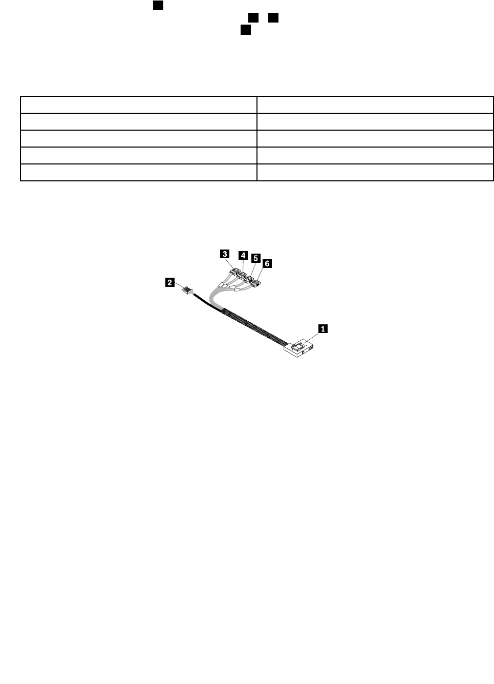
IfyouareconnectingtheSATAharddiskdrivestothesystemboard,usethe450mm(17.72inches)
mini-SASsignalcablewithfourSATAportsandoneSerialGeneralPurposeInput/Output(SGPIO)port.
Connectthemini-SASconnector1tothemini-SASsignalcableconnectoronthe3.5-inchhot-swaphard
diskdrivebackplaneandconnectthefourSATAports
3–6totheSATAconnector0toSATAconnector3
onthesystemboard.Then,connecttheSGPIOport2totheSATASGPIOconnectoronthesystemboard.
Notes:
1.ThenumberonthelabelforeachofthefourSATAsignalcablesindicatesthesequencewhenyouare
connectingthecablestothecorrespondingSATAconnectors(0-3)onthesystemboard.
SATAsignalcablelabelSystemboardSATAconnector
P0
SATAconnector0
P1
SATAconnector1
P2
SATAconnector2
P3
SATAconnector3
2.IfyouconnecttheSATAharddiskdrivestothesystemboard,youcancongureRAIDusingthe
congurationutilityfortheonboardSATAsoftwareRAID.See“ConguringtheonboardSATAsoftware
RAID”onpage75.
Figure25.Mini-SASsignalcablewithfourSATAportsandoneSGPIOport
TheRAIDcardprovidesadvancedSATA/SASRAIDcongurations.IfyouareusingSAShot-swapharddisk
drives,youmusthavetheRAIDcardforconnectingtheSASharddiskdrives.Toconnecttheharddisk
drivestotheinstalledRAIDcard,thefollowingcablesthatcomewiththeRAIDcardarerequired:
Note:TheoptionpackagefortheRAIDcardisdesignedfordifferenttypesofserversandmightcontain
additionalcablesthatarenotrequiredtobeinstalledintoyourserver.
•One700mm(27.56inches)mini-SAStomini-SASsignalcable
•One2-pin200mm(7.87inches)RAIDcardtosystemboardharddiskdriveLEDcable
Chapter3.Productoverview41