Thank you for purchasing this Factory Service Manual CD/DVD from servicemanuals4u.com.
IBM Mobile Systems Hardware Maintenance Manual Volume 2: ThinkPad Computers April 1995 We Want Your Comments! (Please see page 491) This Manual Supports: ThinkPad 340x ThinkPad 355x ThinkPad 360x ThinkPad 370x ThinkPad 700x ThinkPad 701x ThinkPad 720x ThinkPad 750x ThinkPad 755x (2610) (2619) (2620) (9545) (9552) (2630) (9552) (9545) (9545) S82G-1502-03
IBM Mobile Systems Hardware Maintenance Manual Volume 2: ThinkPad Computers April 1995 We Want Your Comments! (Please see page 491) IBM S82G-1502-03
Note Before using this information and the product it supports, be sure to read the general information under “Notices” on page 497.
About This Manual This manual contains service and reference information for IBM* ThinkPad* computer products. Use this manual along with the advanced diagnostic tests to troubleshoot problems effectively. The manual is divided into sections as follows: The Introduction section provides general information, guidelines, and safety information required to service computers.
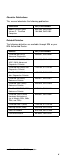
Related Publications The following mobile product publications are available through IBM or your IBM Authorized Dealer.
Obsolete Publications This manual obsoletes the following publication: Publication Part, Form Number Mobile Systems HMM Volume 2: ThinkPad Computers 82G1502, S82G1502 19H1080, S82G1502 Related Diskettes The following diskettes are available through IBM or your IBM Authorized Dealer. * Diskette Part, Form Number ThinkPad 300 (2615) Advanced Diagnostics 33G9361, S33G-9361 ThinkPad 350, 350C, 425, 425C (2618) Advanced Diagnostics Diskette A211000, GA21-1000 ThinkPad 500 (2603) Adv.
vi IBM Mobile Systems HMM
Contents Introduction . . . . . . . . . . . . . Portable Computer Descriptions . . . . Drive and Diskette Compatibility Matrix . Important Service Information . . . . . Safety Notices (Multi-lingual Translations) Safety Information . . . . . . . . . . Laser Compliance Statement . . . . . Screw Size Chart . . . . . . . . . . . . . . . . . . . . . . . . . . . . . . . . . . . . . . . . . . . . . . . . . . . 1 . 2 . 4 . 5 . 7 . 14 . 19 . 20 ThinkPad 340x (IBM 2610) . . . General Checkout . . . . . . . .
Symptom-to-FRU Index . . . . . Related Service Procedures . . . Product Overview . . . . . . . . FRU Removals and Replacements Locations . . . . . . . . . . . . Parts Listing . . . . . . . . . . . . . . . . . . . . . . . . . . . . . . . . . . 331 344 349 350 381 383 ThinkPad 755CE, 755CSE, 755CV, General Checkout . . . . . . . . Symptom-to-FRU Index . . . . . Related Service Procedures . . . Product Overview . . . . . . . . FRU Removals and Replacements Locations . . . . . . . . . . . .
Introduction Portable Computer Descriptions . . . . . . . . . . Drive and Diskette Compatibility Matrix . . . . . . . Important Service Information . . . . . . . . . . . How to Use Error Messages . . . . . . . . . . How to Read POST Error Messages . . . . . . Safety Notices (Multi-lingual Translations) . . . . . Safety Information . . . . . . . . . . . . . . . . General Safety . . . . . . . . . . . . . . . . Electrical Safety . . . . . . . . . . . . . . . . Safety Inspection Guide . . . . . . . . . . . .
Portable Computer Descriptions All models in the following table have VGA video. Models N51, CL57, and P70/75 and Thinkpads 700x and 720x are Micro Channel* systems. All others are AT* bus systems.
Model Type ThinkPad 701C ThinkPad ThinkPad ThinkPad ThinkPad ThinkPad ThinkPad ThinkPad ThinkPad ThinkPad ThinkPad ThinkPad ThinkPad ThinkPad ThinkPad ThinkPad ThinkPad ThinkPad ThinkPad C M P 2630 2630 2630 2630 701Cs 2630 2630 2630 2630 710T 2523-09Y 2523-302 2523-303 720 9552-307 9552-308 720C 9552-30J 730T 2524 2524 750 9545-006 9545-008 750C 9545-306 9545-308 750Ce 9545 750Cs 9545 9545 750P 9545-40C 9545-40E 755C 9545 9545 9545 9545 9545 9545 755CD 9545 9545 755CDV 9545 9545 755Ce 9545 9545
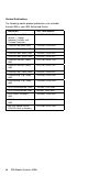
Drive and Diskette Compatibility Matrix The following table provides identification information for 3.5-inch drives. Diskette Drive Identifying Mark 3.5-Inch - 1.44MB 3.5-Inch - 2.88MB 1.44 on the eject button 2.88 on the eject button The following table provides compatibility information for 3.5-inch diskettes and 3.5-inch diskette drives. Diskette Capacity 1.44MB Drive 2.88MB Drive 1.0MB 2.0MB 4.
Important Service Information Important Diskette fixes are customer installable. The diskette fixes are located on the PC Company Bulletin Board Service (BBS). The direct phone line for modem connection is 919-557-0001 or tieline 255-0001. Advise customers to contact the PC Company HelpCenter at 800-772-2227 if they need assistance in obtaining or installing any diskette fixes. Customers in Canada should call IBM HelpPC at 800-565-3344 for assistance or down-load information.
The advanced diagnostic tests are intended to test only IBM products. Non-IBM products or modified options can give false errors and invalid responses. Hard Disk Drive Replacement Strategy: Always try to run a low-level format before replacing a hard disk drive. Warning: The drive startup sequence in the computer you are servicing might have been changed. Be extremely careful during write operations such as copying, saving, or formatting.
Safety Notices (Multi-lingual Translations) In this manual, safety notices appear in English with a page number reference to the appropriate multi-lingual, translated safety notice found in this section. The following safety notices are provided in English, French, German, Italian, and Spanish languages. Safety Notice 1 Before the computer is powered-on after FRU replacement, make sure all screws, springs, or other small parts are in place and are not left loose inside the computer.
Safety Notice 2 Some standby batteries contain a small amount of nickel and cadmium. Do not disassemble it, recharge it, throw it into fire or water, or short-circuit it. Dispose of the battery as required by local ordinances or regulations. Use only the battery in the appropriate parts listing. Use of an incorrect battery can result in ignition or explosion of the battery. Certaines batteries de secours contiennent du nickel et du cadmium.
Safety Notice 3 The battery pack contains small amounts of nickel. Do not disassemble it, throw it into fire or water, or short-circuit it. Dispose of the battery pack as required by local ordinances or regulations. Use only the battery in the appropriate parts listing when replacing the battery pack. Use of an incorrect battery can result in ignition or explosion of the battery. La batterie contient du nickel. Ne la démontez pas, ne l'exposez ni au feu ni à l'eau. Ne la mettez pas en court-circuit.
Safety Notice 4 The lithium battery can cause a fire, explosion, or severe burn. Do not recharge it, remove its polarized connector, disassemble it, heat it above 100°C (212°F), incinerate it, or expose its cell contents to water. Dispose of the battery as required by local ordinances or regulations. Use only the battery in the appropriate parts listing. Use of an incorrect battery can result in ignition or explosion of the battery. La pile de sauvegarde contient du lithium.
Safety Notice 5 If the LCD breaks and the fluid from inside the LCD gets into your eyes or on your hands, immediately wash the affected areas with water for at least 15 minutes. Seek medical care if any symptoms from the fluid are present after washing. Si le panneau d'affichage à cristaux liquides se brise et que vous recevez dans les yeux ou sur les mains une partie du fluide, rincez-les abondamment pendant au moins quinze minutes. Consultez un médecin si des symptômes persistent après le lavage.
Safety Notice 6 To avoid shock, do not remove the plastic cover that surrounds the lower portion of the inverter card. Afin d'éviter tout risque de choc électrique, ne retirez pas le cache en plastique protégeant la partie inférieure de la carte d'alimentation. Aus Sicherheitsgründen die Kunststoffabdeckung, die den unteren Teil der Spannungswandlerplatine umgibt, nicht entfernen. Per evitare scosse elettriche, non rimuovere la copertura in plastica che avvolge la parte inferiore della scheda invertitore.
Safety Notice 8 Before removing any FRU, power-off the computer, unplug all power cords from electrical outlets, remove the battery pack, then disconnect any interconnecting cables. Avant de retirer une unité remplaçable en clientèle, mettez le système hors tension, débranchez tous les cordons d'alimentation des socles de prise de courant, retirez la batterie et déconnectez tous les cordons d'interface.
Safety Information The following section contains the safety information that you need to be familiar with before servicing an IBM mobile computer. General Safety Follow these rules to ensure general safety: 14 Observe good housekeeping in the area of the machines during and after maintenance. When lifting any heavy object: 1. Ensure you can stand safely without slipping. 2. Distribute the weight of the object equally between your feet. 3. Use a slow lifting force.
Electrical Safety Observe the following rules when working on electrical equipment. Important Use only approved tools and test equipment. Some hand tools have handles covered with a soft material that does not insulate you when working with live electrical currents. Many customers have, near their equipment, rubber floor mats that contain small conductive fibers to decrease electrostatic discharges. Do not use this type of mat to protect yourself from electrical shock.
Regularly inspect and maintain your electrical hand tools for safe operational condition. Do not use worn or broken tools and testers. Never assume that power has been disconnected from a circuit. First, check that it has been powered-off. Always look carefully for possible hazards in your work area. Examples of these hazards are moist floors, nongrounded power extension cables, power surges, and missing safety grounds.
The guide consists of a series of steps presented in a checklist. Begin the checks with the power off, and the power cord disconnected. Checklist: 1. Check exterior covers for damage (loose, broken, or sharp edges). 2. Power-off the computer. Disconnect the power cord. 3. Check the power cord for: a. A third-wire ground connector in good condition. Use a meter to measure third-wire ground continuity for 0.1 ohm or less between the external ground pin and frame ground. b.
Handling Electrostatic Discharge-Sensitive Devices Any computer part containing transistors or integrated circuits (ICs) should be considered sensitive to electrostatic discharge (ESD). ESD damage can occur when there is a difference in charge between objects. Protect against ESD damage by equalizing the charge so that the machine, the part, the work mat, and the person handling the part are all at the same charge. Notes: 1. Use product-specific ESD procedures when they exceed the requirements noted here.
Laser Compliance Statement The CD-ROM drive in the ThinkPad computer is a laser product. The CD-ROM drive's classification label (shown below) is located on the drive. CLASS 1 LASER PRODUCT LASER KLASSE 1 LUOKAN 1 LASERLAITE APPAREIL A LASER DE CLASSE 1 KLASSE 1 LASER APPARAT The CD-ROM drive is certified in the U.S. to conform to the requirements of the Department of Health and Human Services 21 Code of Federal Regulations (DHHS 21 CFR) Subchapter J for Class 1 laser products.
Screw Size Chart Use the chart below to match the size and shape of the screws used in the computer you are servicing.
Screw Size Chart (continued): Use the chart below to match the size and shape of the screws used in the computer you are servicing.
Screw Size Chart (continued): Use the chart below to match the size and shape of the screws used in the computer you are servicing.
ThinkPad 340x (IBM 2610) General Checkout . . . . . . . . . . . . . . . Memory Checkout . . . . . . . . . . . . . System Board . . . . . . . . . . . . . . . Keyboard/Auxiliary Input Device Checkout . . TrackPoint II and III Checkout . . . . . . . Diskette Drive Test . . . . . . . . . . . . Power Systems Checkout . . . . . . . . . Power Management Features . . . . . . . Symptom-to-FRU Index . . . . . . . . . . . . Numeric Error Codes . . . . . . . . . . . . FRU Codes . . . . . . . . . . . . . . . .
Indicator Card . . . . . . . . . . . . . . . . . 61 Parts Listing . . . . . . . . . . . . . . . . . . . 62 Option Parts List . . . . . . . . . . . . . . . .
General Checkout Use the following procedure as a guide for computer problems. The diagnostic tests are intended to test only IBM products. Non-IBM products, prototype cards, or modified options can give false errors and invalid system responses. 1. Obtain the failing symptoms in as much detail as possible. 2. Verify the symptom. Attempt to recreate the failure by running the diagnostic tests or retrying the same operation. Note: To run the diagnostics, refer to “How to Run the Diagnostics” on page 45. 3.
Memory Checkout See the following table for the available memory size of each card. IC DRAM Memory size 0 MB 3712 KB 2 MB 5760 KB 4 MB 7808 KB 8 MB 11904 KB Memory errors might stop system operations, show error messages on the screen, or hang the system. Use the following procedure to isolate memory problems. Note: Make sure that the memory card is fully installed into the connector. Loose connections can cause errors. 1.
System Board The processing functions for the computer are performed by the system board. When a numeric code calls out the system board, use the following procedure to isolate the problem. 1. Run the system board test to verify the symptom. This test verifies the system board. If no error is detected, return to “General Checkout” on page 25. 2. If FRU code 10 appears, replace the system board. 3. Rerun the test to verify the fix.
If any of the above devices do not work, reseat the cable connector and repeat the failing operation. If the problem does not occur again, recheck the connector. If the problem is not corrected, replace the device, and then the system board. TrackPoint II and III Checkout If the TrackPoint II or III will not work, check the configuration in Easy-Setup by selecting Keyboard from the Config menu. If the configuration of the TrackPoint II or III is disabled, select TrackPoint to enable it.
space key. A √ mark appears next to the selected icon. Insert the blank diskette when instructed. 2. Run the diskette drive test. 3. If the controller test detects an error, FRU code 10 appears. Replace the system board. 4. If the controller test runs without errors, the drive read/write tests start automatically. 5. If the drive test detects an error, FRU code 50 appears. If the diskette itself is known to be good, replace the drive. If no errors occur at the FDD position, the drive is not defective.
AC Adapter (30W, 40W): 2 1 Pin Voltage (V dc) 1 +17.1 to +18.9 2 Return AC Adapter (35W): 2 1 Pin Voltage (V dc) 1 +15.5 to +17.0 2 Return If the voltage is correct, replace the system board. If the problem is not corrected, go to “Undetermined Problems” on page 42. If the voltage is not correct, go to the next step. Unplug the AC Adapter cable from the ac power outlet and wait five minutes or longer to allow the protection circuit to be fully discharged and initialized.
1 ( 3 4 ( ( ) ) ) Voltage (V dc) / Signal Terminal 340 (NiCd) 340CSE (NiMH) 1 +10.0 to +18.0 +10.0 to +16.0 2 NC 0 Ω+0 ground (−) 3 10 kΩ between ground (−) 4 Ground (−) 3. If the voltage is less than +10.0 V dc, the battery pack has been discharged or is defective. Recharge the battery. If the recharging does not work, go to Step 5 to check the charging circuit. If the voltage is still less than +10.0 V dc after the recharging, replace the battery. 4. If the voltage is more than +8.
Red Black Wire Voltage (V dc) Red +2.9 to +3.3 Black Ground If the voltage is correct, replace the system board. If the voltage is not correct, the backup battery has been discharged. Replace the backup battery. If the backup battery discharges quickly after replacement, replace the system board. Checking the Standby Battery: Be careful not to cause a short circuit when measuring the voltage. 1. Power-off the computer and unplug the AC Adapter from the computer. 2.
Black Red Pin Voltage (V dc) + +4.0 − Ground If the voltage is less than +4.0 V dc, replace the system board. If the voltage is more than +4.0 V dc, power-off the computer, replace the standby battery, and go to the next step. Ensure that the AC Adapter is plugged into the computer; then power-on the computer. Charging of the standby battery starts. A depleted battery needs approximately 30 minutes to be recharged to the operational voltage of +3.5 V dc. Unplug the AC Adapter.
Suspend Mode: When in suspend mode, the following occurs: The LCD power is powered-off. The hard disk is powered-off. The CPU is stopped. Notes: 1. In the ThinkPad Features Program, the computer can be set to “Will not suspend even if LCD is closed.” 2. When the computer is powered with ac power and is used with one of the following IBM PC cards, the computer enters standby mode; the PC card and application program remain active.
Numeric Error Codes Symptom/Error FRU/Action 10X 1. System Board 110 1. Go to “Memory Checkout” on page 26. 2. IC DRAM Card 3. System Board 111 1. Go to “Memory Checkout” on page 26. 2. System Board 161 1. Go to “Checking the Backup Battery” on page 31. 2. Backup Battery 3. System Board 163 (Time and Date was not set.) 1. Set Time and Date. 2. System Board 173 (Configuration data were lost.) 1. Select OK in the error screen; then set time and date. 2. Backup Battery 3.
Symptom/Error FRU/Action 301, 303, 304, 305, 3XX 1. Go to “Keyboard/Auxiliary Input Device Checkout” on page 27. 2. Keyboard 3. External Numeric Keypad 4. External Keyboard 5. Keyboard/Mouse Cable 6. System Board 601, 6XX 1. Go to “Diskette Drive Test” on page 28. 2. Diskette Drive Assembly 3. Diskette 4. System Board 602 (Diskette read error.) 1. Go to “Diskette Drive Test” on page 28. 2. Diskette 3. Diskette Drive Assembly 604 (Non-acceptable ID was read from the diskette drive.) 1.
Symptom/Error FRU/Action I9990301 I9990302 I9990305 1. Reseat the boot device. 2. Check the startup sequence for the correct boot device. 3. Check that the operating system has no failures, and is installed correctly. I9990303 1. System Board Other codes not listed above 1. Go to “Undetermined Problems” on page 42. FRU Codes If an error is detected by the diagnostic tests, a four-digit FRU code is displayed. The FRU code indicates two suspected FRUs.
Beep Symptoms Symptom/Error FRU/Action Continuous beeps. 1. System Board One beep and a blank, unreadable, or flashing LCD. 1. Reseat the LCD connector. (See “1090 LCD Assembly” on page 55.) 2. LCD Assembly 3. System Board One beep, and the message “Unable to access boot source.” 1. Reseat the boot device. 2. Boot Device 3. System Board One long, two short beeps and a blank or unreadable LCD. 1. System Board 2.
Symptom/Error FRU/Action No beep during POST, but system runs correctly. 1. Turn the volume up and listen to the speaker. 2. Speaker LCD Related Symptoms Symptom/Error FRU/Action Flicker 1. Do not replace any FRUs. In certain brightness/contrast settings, screen flicker can be seen because of technical limitations. No beep, power-on indicator on, and a blank LCD during POST. 1.
Keyboard/TrackPoint II or III Related Symptoms Symptom/Error FRU/Action Keyboard (one or more keys) does not work, or works intermittently. 1. Reseat the three keyboard cables. 2. Reseat the keytop. Ensure the rubber dome under the keytop is straight and in the correct direction, with the larger radius on the top. 3. Keyboard 4. System Board TrackPoint II or III does not work. 1. Go to “TrackPoint II and III Checkout” on page 28. 2. Keyboard 3.
Function/Audio Related Symptoms Symptom/Error FRU/Action The system will not suspend or resume by opening or closing the keyboard. 1. Go to “Suspend Mode” on page 34 and check that the computer can enter suspend mode. 2. Go to the Easy-Setup screen and press Fn+4. If the computer enters suspend mode, suspect that the application program is defective. 3. System Board The system will not suspend or resume by opening or closing the LCD. 1.
Peripheral Device Related Symptoms Symptom/Error FRU/Action External display does not work correctly. 1. See “External Display Self-Test” in the “Common Devices Checkout” section. Printer problems. 1. 2. 3. 4. Serial or parallel port device problems. 1. Device 2. Device Cable 3. System Board Run Printer Self-test. System Board Parallel Port Device Cable Other Symptoms Symptom/Error FRU/Action PCMCIA slot pin is damaged. 1.
2. Check the cables, wires, and connectors for short circuits and open circuits. Visually check them for damage. If any problems are found, replace the FRU. 3. Remove or disconnect all of the following devices. a. Non-IBM devices b. Devices attached to the expansion bus connector c. Printer, mouse, and other external devices d. Battery pack e. IC DRAM card f. PC cards Note: Remember that removing the hard disk drive, an IC DRAM card, or any adapter or device, might cause configuration errors.
Status Indicators The system status indicators show the current computer status in different colors (green, yellow, and orange). Symbol Color Meaning Green Battery is fully charged. Yellow (340) Battery usable. Battery is charging (when the AC Adapter is used). Note: When the battery is fully charged, the indicator turns and stays green. Orange Battery is low Blinking orange Battery is almost depleted Blinking yellow (340) Battery cannot be charged because of it's high temperature.
Symbol Color Meaning Green Computer is powered on How to Run the Diagnostics Use either the TrackPoint II or III or the cursor move keys to interact with the tests. The Enter key works the same as selecting the OK icon to reply OK. 1. Press and hold the F1 key; then power-on the computer. Hold the F1 key down until the Easy-setup screen appears. 2. Select Test and press Enter. 3. Select a device and press Enter to run the test. 4. The test progress screen appears. 5.
Reset Pushbutton The reset pushbutton resets the system and forces the power to be powered-off . Note: Use this pushbutton when the power is not completely off or the system is hung. See “System Board” on page 61 for the location of the pushbutton. Checking the Installed Devices List If a device is installed but the icon appears in a gray shade rather than a dark shade on the basic diagnostics screen, the device is defective. Reseat the device connectors.
Fn Key Combinations The following table shows the Fn key and function key combinations and their corresponding functions. The Fn key works independently from the operating system. The operating system obtains the status through the system management interface to control the system.
Product Overview The following table shows an overview of the system features. Feature Processor Description 340 – IBM486 SLC 25/50MHz, on the system board 340CSE – IBM486 SLC2 25/50MHz, on the system board – IBM486 SLC2 33/66MHz, on the system board Memory (Standard) 4MB (on the system board) Memory (Option) 2MB, 4MB, 8MB, IC DRAM card (12MB is maximum) CMOS RAM 128 Bytes VGA Video Diskette Drive Hard Disk Drive PCMCIA 48 340 – 9.
FRU Removals and Replacements This section contains information about removals and replacements. An electrostatic discharge (ESD) strap must be used to establish personal grounding. The system board is sensitive to, and can be damaged by, electrostatic discharge. Establish personal grounding by touching a ground point with one hand before touching these units. Do not damage any part. Only certificated and trained personnel should service the computer.
1010 Rear Connector Door Remove the rear connector door by flexing it.
1030 Backup Battery 1040 IC DRAM Card 1050 Standby Battery Battery Pack (1020) Step 2: Step 3: Step 4: Standby Battery IC DRAM Card Backup Battery Note The IC DRAM card is sensitive to physical shock. Incorrect handling of the card can damage it. Note: When removing the backup battery or standby battery, use the connector extractor (P/N 39G9977).
1060 Top Cover Battery Pack (1020) 1 Step Location (Quantity) Length .1/ Base cover (3) 12 mm Note: Make sure you use the correct screw.
1070 Indicator Card Battery Pack (1020) Top Cover (1060) 1 When Replacing Be careful to not break the pins of the indicator card connector.
1080 Keyboard Unit Battery Pack (1020) Top Cover (1060) Notes: 1. There are two keyboard latches on each side of the computer frame. Slide the keyboard as shown in step 2 to release the keyboard from those latches; them remove the keyboard. (Small arrows on the both sides of the keyboard show the locations of the latches.) 2. The keyboard has three cables; be careful not to damage the cables when you open the keyboard and to remove them.
1090 LCD Assembly Battery Pack (1020) Top Cover (1060) Safety Notice 5: Translation on page 11 If the LCD breaks and the fluid from inside the LCD gets into your eyes or on your hands, immediately wash the affected areas with water for at least 15 minutes. Seek medical care if any symptoms from the fluid are present after washing. Caring for the LCD When cleaning of the LCD becomes necessary, gently wipe the LCD with a dry, soft cloth. Do not use alcohol or detergent to clean the LCD.
4 3 3 Use the following table for reference when replacing parts. Step Location (Quantity) Length .1/ LCD cable (1) 6 mm .3/ LCD hinge (4) 8 mm Note: Make sure you use the correct screw.
1100 Diskette Drive 1110 Hard Disk Drive Battery Pack (1020) Top Cover (1060) Keyboard Unit (1080) Steps 1, 2, 3, 4: Diskette Drive Steps 5, 6: Hard Disk Drive When Replacing Before removing the hard disk drive, have the user make a backup copy of all information on the hard disk Never remove the hard disk drive while the system is operating or is in suspend mode. Do not pull the hard disk cable. The cable can be damaged if it is disconnected without releasing the latch.
1120 System Board/Speaker Rear Connector Door (1010) Battery Pack (1020) Backup Battery (1030) IC DRAM Card (1040) Standby Battery (1050) Top Cover (1060) Indicator Card (1070) Keyboard Unit (1080) Diskette Drive (1100) Hard Disk Drive (1110) Step 1, 2, 3, 4: System Board Step 4, 5: Speaker 2 1 3 4 5 Step Location (Quantity) Length .1/ I/O connector (6) Hex-head screws .2/ Base cover (1) 8 mm .3/ Base cover (2) 12 mm Note: Make sure you use the correct screws.
Locations System (Front View) .1/ .2/ .3/ .4/ .5/ .6/ .7/ .8/ .9/ .1ð/ .
System (Rear View) .1/ .2/ .3/ .4/ .5/ .6/ .7/ External Display Connector Serial Connector PCMCIA Slot Serial Connector Reset Pushbutton Power Jack External Input Device connector 7 6 5 4 3 2 1 System (Interior View) .1/ .2/ .3/ .
System Board .1/ Internal Modem Card connector (Modem model only) .2/ External Display Connector .3/ Parallel Connector .4/ LCD connectors .5/ PCMCIA Slot .6/ Indicator Card Connector .7/ Reset Pushbutton .8/ LCD Inverter Power Connector (340CSE) .9/ Serial Connector .1ð/ Power Jack .11/ External Input Device Connector .12/ Keyboard Signal Connector .13/ Hard Disk Drive Connector .14/ Speaker Connector (340CSE only) .15/ Keyboard TrackPoint II/III Connector .16/ Battery Pack Terminal .17/ POP Terminal .
Parts Listing 1 2 3 17 4 16 5 6 15 7 8 14 9 13 10 11 12 62 IBM Mobile Systems HMM
System Unit Models 340 and 340CSE Index 1 LCD Assembly (340) 84G6678 1 LCD Assembly (340CSE) 9.4-inch 85G7601 10.4-inch 85G7602 2 Top Cover (340) 84G6677 2 Top Cover (340CSE) 85G7600 3 Keyboard Assembly (See keyboard list) 4 Modem/Fax Card (2400 bps.
DASD Index 15 Diskette Drive (2-mode) Diskette Drive (3-mode) 16 Speaker (360CSE) 17 TrackPoint II Cap 17 TrackPoint III Cap Shield Plate (340) AC Adapter For Japan AC Adapter (small, 35W) For Japan DC Plug IC DRAM Card (See options) 84G6664 84G6665 85G7643 66G6444 84G6536 84G6774 84G6679 84G6738 85G4952 85G6669 85G6664 Keyboards Arabic Belgium Canadian French Danish Dutch Finnish, Swedish French German (Black) Greek Hebrew Italian Japanese Latin Spanish Norwegian Portuguese Spanish Swiss, French Swiss, G
Option Parts List Notes: 1. When you replace the AC Adapter with a new one, use the one for the country you are in even if the system is from a different country. 2. The warranty for the system unit does not apply to all options.
1 6 2 7 3 8 4 9 5 10 Warning: Use only the power cord certified for your country. 30/40W 35W Colombia, U.S., Venezuela 13F9959 25H2207 Japan, 2-pin 6454377 85G6665 Japan, 3-pin 65F0031 2 Hong Kong, Singapore, U.K.
ThinkPad 700, 700C, 720, 720C (9552) General Checkout . . . . . . . . . . . . . . Memory Checkout . . . . . . . . . . . . Power Systems Checkout . . . . . . . . Power Management Features . . . . . . Symptom-to-FRU Index . . . . . . . . . . . Numeric Error Codes . . . . . . . . . . . Beep Symptoms . . . . . . . . . . . . . Miscellaneous Symptoms . . . . . . . . Undetermined Problem . . . . . . . . . . Related Service Procedures . . . . . . . . . System Status Indicators . . . . . . . . .
General Checkout The diagnostic tests are intended to test only IBM products. Non-IBM products, prototype card, or modified options can give false errors and invalid system responses. Warning: The drives might have been rearranged or the drive startup sequence might have been altered. Be extremely careful during write operations such as copying, saving, or formatting. Data or programs can be written over if you select an incorrect drive.
Symptom Go to ...
Memory Checkout Customer diagnostics can eliminate defective memory so no memory error message appears at power-on reset. After you replace a defective base memory card or IC DRAM card, run Automatic configuration. Otherwise, the new memory will not be recognized. Power-off the computer before you remove or replace any parts. 001 – Remove all IC DRAM cards from their slots (if installed). – Power-off the computer, then power it on.
007 (continued) – Run the memory test. Use the RUN TESTS ONE TIME option. DID THE MEMORY TESTS END WITHOUT AN ERROR? Yes No 008 Replace the IC DRAM card in slot 2. If the problem is not corrected, replace the system board. 009 If the problem occurs intermittently, run the memory tests multiple times to create an error log. Power Systems Checkout Note: One or all of the batteries can discharge if there is a short circuit in the system. 1.
Checking the AC Adapter: If the Power-On indicator does not turn-on, check the power cord of the AC adapter for correct continuity and installation. 1. If any noise can be heard from the AC adapter when it is plugged into the ac power outlet, replace the AC adapter. If no noise can be heard from the AC adapter, go to step 3. 2. If a noise is still heard from the new AC adapter, suspect the computer. Replace the AC adapter with the original one, then go to the next step.
Checking the Car Battery Adapter (700 only): If the output voltage from the cigarette lighter socket of the car is less than 10.5 V dc, the power-on indicator on the car battery adapter blinks and a noise can be heard continuously. 1. Unplug the car battery adapter cable from the connector, if connected. 2. Plug the car battery adapter into the cigarette lighter socket.
Checking the Battery Pack 1. Carefully place the computer bottom-side up. 2. Remove the battery pack and measure the voltage between the battery terminals 1 (+) and 3 (−). See the following figure. 1 ( ) 2 3 ( ) ( ) Pin Voltage (V dc) 1 +10.0 to +18.0 2 Thermal Detection 3 Ground If the voltage is less than +10.0 V dc, the battery pack has been discharged or is defective. If the voltage is more than +10.0 V dc, go to the next step. 3.
Checking the Backup Battery 1. Carefully place the computer bottom-side up. 2. Remove the bottom cover. 3. Disconnect the battery connector from the system board. 4. Measure the voltage of the backup battery. See the following figure. (Red) (Black) Wire Voltage (V dc) Red +2.5 to +3.7 Black Ground If the voltage is correct, replace the system board. If the voltage is not correct, the backup battery has been discharged by a short circuit or it is defective.
2 1 Pin Voltage (V dc) 1 +4 2 Ground If the voltage is less than +4 V dc, replace the voltage converter. If the voltage is more than +4 V dc, go to the next step. Power-off the computer and unplug the AC adapter cable from the computer. Reconnect the standby battery to the voltage converter. Plug the AC adapter cable into the computer and power-on the computer. Allow approximately 30 minutes for the standby battery to charge.
If the problem is not corrected, replace the quick charger or the power cord. 3. Install the battery pack into the quick charger. If the charging indicator does not start blinking, replace the quick charger. Checking the Voltage Converter (700, 700C): Use the following procedure to isolate a problem with the ThinkPad 700, 700C voltage converter. Note: If the problem only occurs when using the computer with a good battery pack, replace the voltage converter. 1. Power-off the computer. 2.
GND Password-Override Connecter VC VB VG VA PWRGOOD Note: Only VOLT is marked on the system board. Use the above figure to locate the VA, VG, VB, VC, and PWRGOOD signal names. If all voltages are correct, the voltage converter is operating correctly. If the voltages are not correct, go to the next step. Power-off the computer and unplug the AC adapter cable from the computer. Check for a short circuit between GND and VA, VG, VB, or VC.
6. Open the LCD half-way, then stand the computer on its front edges so that the suspend switch is not activated. 7. Power-on the computer. 8. Check the voltages of the voltage converter on the system board. See the following figure. Notes: a. Make sure the suspend switch (located to the left above the keyboard) is not activated during measurement of the voltage. b. Only PG is marked on the system board. Use the following figure to locate the VA, VG, VB, VA3, and VB3 signal names.
If there is a short circuit (less than 10 ohms), remove the FRUs indicated one at a time until the short circuit disappears. Replace the FRU causing the short circuit. FRU VA VG VB Voltage converter Processor card System board Video card Base memory card Keyboard control card Math coprocessor Diskette drive Hard disk drive LCD Indicator assembly x x x x x x x x x x x x x x x VA3 VB3 x x x x x x x x x x 11. If there is no short circuit, replace the following FRUs one at a time.
Power Management Features The suspend and resume functions are unique methods used to save battery power. In suspend mode, all tasks are suspended and their present states are stored in memory to save power. Also, the system enters a sleep state where only a minimum amount of power is used. When the computer returns to normal operation using the resume function, the computer restores the same states as when it entered suspend mode.
Symptom-to-FRU Index The Symptom-to-FRU Index lists error symptoms and possible causes. The most likely cause is listed first. Always begin with “General Checkout” on page 68. This index also can be used to help you decide which FRUs to have available when servicing a computer. If you cannot correct the problem using this index, go to “Undetermined Problem” on page 93. IMPORTANT: 1. If you have both an error message and an incorrect audio response, diagnose the error message first. 2.
Symptom/Error 000118XX FRU/Action 1. Clear Error Log. See “System Error Log” on page 96. 2. If the error remains, replace the FRUs in the following order: Base Memory Card IC DRAM Card Note: Error Log must be cleared when a FRU is replaced. 00016100 1. See “Checking the Backup Battery” on page 75. 2. System Board 3. Voltage Converter 00016300, 00016400, 00016500, 00016900 (If 00016300 appears, set date and time first in the Reference Diskette.
Symptom/Error FRU/Action 000187XX 1. Set Configuration 2. System Board 000188XX 1. System Board 000189XX 1. Select More utilities to clear the system error log. 00019000 1. Reseat System Board 2. Reseat CPU chip / Processor Card 3. System Board 00019102 1. Rerun diagnostics tests. 2. If error remains, see 000191XX. 000191XX (Not listed above) 1. Reseat System Board 2. Reseat CPU chip / Processor Card 3. System Board 00019200 1. Voltage Converter 2. Keyboard Control Card 3.
Symptom/Error FRU/Action 0002XXXX (See “Memory Checkout” on page 70 before replacing any FRUs.) 1. Base Memory Card 2. IC DRAM Card 3. System Board 00030100, 00030500 (Power-on the computer before external devices.) (See “1080 Keyboard Unit” on page 54 before replacing any FRUs.) 1. Keyboard Control Card 2. System Board 3. Keyboard 4.
Symptom/Error FRU/Action 0014XXXX 00180100, 00186100 1. See “Printer Checkout” on page 474 before replacing any FRUs. 2. Printer 3. System Board Replace the line QEMM386.SYS with QEMM386.SYS XBDA:L in Config.sys. 0024XX00 1. Video Card 2. System Board 3. Voltage Converter (700C, 720C only) 0039G900 1. System Board 005002XX, 005006XX, 005008XX, 005041XX 1. See “External Display Self-Test” on page 470 before replacing any FRUs. 2. Video Card 3. External Display 4. LCD 5.
Symptom/Error FRU/Action 00861100, 00861200 00861300 See “1080 Keyboard Unit” on page 54 before replacing any FRUs. 1. Keyboard Control Card 2. Keyboard (Pointing Stick) 3. System Board 4. Ext. Keyboard Cable 00861XXX (not listed above) See “1080 Keyboard Unit” on page 54 before replacing any FRUs. 1. Keyboard (Pointing Stick) 2. Keyboard Control Card 3. System Board 00862100, 00862200 See “1080 Keyboard Unit” on page 54 before replacing any FRUs. 1. Keyboard Control Card 2. System Board 3.
Symptom/Error FRU/Action 0137XXXX 1. 2. 3. 4. 5. 0194XXXX 1. Do not replace any FRUs. The installed Memory Expansion Adapter is not supported by IBM. I99903XX, I99900XX I99800XX 1. Reseat the hard disk drive to ensure good connection. 2. See “Set Startup Sequence” on page 98. 3. Hard Disk Drive 4. System Board I999XXXX Serial Adapter System Board Video Card Any Serial Device Communication Cable Restore the system partition from the Reference Diskette.
Symptom/Error Two long beeps and two short beeps (or two long beeps and no short beeps). (Possibly with a blank screen and blinking speaker icon.) FRU/Action 1. Video Card 2. Incorrect system board (700, 700C) 3. Incorrect processor upgrade (700, 700C) 4. Incorrect 240MB hard disk drive upgrade for this model Miscellaneous Symptoms Symptom/Error FRU/Action Power-on password is not reactivated. 1. Check the power-on password switch position. Problem occurs only when port replicator installed. 1.
Symptom/Error FRU/Action LCD screen unreadable or characters missing pels. 1. See important note for “LCD FRU Replacement Notice” on page 124. 2. LCD Assembly 3. System Board LCD too dark, unable to adjust contrast or brightness. 1. LCD 2. Video Card LCD slightly dims when changing to battery power. 1. Normal operation (Dimming of LCD conserves battery power.) LCD unreadable, illegible, or distorted. 1. LCD 2. Video Card 3. System Board LCD cannot be powered-on or off. 1. Video Card 2.
Symptom/Error FRU/Action Mouse and Pointing Stick problems. 1. See “1080 Keyboard Unit” on page 54 before replacing any FRUs. 2. Disable Trackpoint and test Mouse again. The Trackpoint can interfere with the operation of some Mouse devices. 3. Mouse 4. Keyboard Control Card 5. Keyboard Cursor floats or moves erratically. 1. See “TrackPoint II Checkout” on page 476 before replacing any FRUs. 2. Mouse 3. Keyboard External display problems. 1.
Symptom/Error FRU/Action Real-time clock inaccurate. 1. See “Checking the Backup Battery” on page 75 before replacing any FRUs. 2. Backup Battery 3. System Board Printer problems. 1. See “Printer Checkout” on page 474 Serial or serial port device problems. 1. Device 2. Cable 3. Serial Adapter (if attached) 4. System Board Parallel or parallel port device problems. 1. Device/printer 2. Cable 3. Parallel Adapter (if attached) 4.
Undetermined Problem You are here because the diagnostic tests did not identify which adapter or device failed, the Devices List is incorrect or the system is inoperative. Follow the procedures below (do not isolate FRUs that are known to be good). Check the power supply that was being used at the time of the failure. (See “Power Systems Checkout” on page 71.) If the power supply is operating correctly, continue with the following procedure. 1. Power-off the computer. 2.
Related Service Procedures This section provides information on the following: “System Status Indicators” “Check Point (CP) Codes” on page 96 “System Error Log” on page 96 “Checking the Installed Devices List” on page 97 “Power-On Password (700, 700C)” on page 97 “Power-On Password (720, 720C)” on page 97 “Privileged-Access Password (PAP)” on page 97 “Set Startup Sequence” on page 98 “Restore System Partition” on page 98 “Hard Disk Low Level Format” on page 99 “Replacing the Hard Disk Drive” on page 99 “Sys
Symbol + State Status Indicated Green Battery pack is fully-charged. Yellow Battery pack is half-charged. Orange Battery pack is one-fourth charged. Blinking Orange Battery pack is almost discharged (replace with fully charged spare). Off Battery pack is completely discharged. Battery pack is removed from computer. Computer is off. Computer is using external power; car battery or AC power.
Symbol State Status Indicated On Computer is powered-on (blinking indicates temperature too high - system enters suspend mode until temperature returns to normal). Check Point (CP) Codes Codes beginning with “CP” are displayed on the LCD to indicate system status during POST. The CP codes vary with the level of microcode installed and the type of processor card installed. The CP codes are not error codes. If the system detects an error, the CP code is changed to a POST error message.
instructions on the screen to help you determine which FRU might be causing the failure. Checking the Installed Devices List The Installed Devices List shows the adapters and devices installed in the computer. If an adapter or a device is missing from the list, one of the following conditions might be the cause. Warning: A customized setup configuration (other than default settings) might exist on the system you are servicing. Running Automatic Configuration can alter the settings.
Set Startup Sequence 1. Power-off the computer. 2. Insert the backup copy of the Reference Diskette into the diskette drive. 3. Power-on the computer. 4. Select Set features from the Main Menu. 5. Select Set startup sequence. If you cannot set the startup sequence, replace the system board. 6. Check the list of devices on the Set startup sequence screen. 7. Is the hard disk drive in the list as a startup device? Yes Exit from this screen and the Main Menu.
Hard Disk Low Level Format To format the hard disk and restore the system partition, do the following. Warning: The following procedure causes permanent loss of the data on the hard disk. Make sure that a backup of all the information on the hard disk is made. 1. Power-off the computer. 2. Insert the backup copy of the Reference Diskette into the diskette drive. 3. Power-on the computer. 4. Proceed to the Main Menu. Press Ctrl+A to display the Advanced Diagnostic Menu. 5.
System Diskettes (Reference and Diagnostic) If the hard disk drive is not operational, you can run the system programs from the Reference Diskette. Note: The Reference Diskette contains the system programs and the Diagnostic Diskette contains the test programs. The Diagnostic Diskette is not self-starting. To run the Diagnostic Diskette, start the system from the Reference Diskette, select Test the computer, then follow the instructions on the screen.
not have a backup copy of the current system partition, but you have the option diskettes, go to step 8 on page 101. 7. Select Copy an option diskette from the Main Menu. When the INSERT YOUR OPTION DISKETTE message appears, insert the backup copy of the system partition and follow the instructions on the screen. (The backup copy of the system partition is used to reinstall the option files onto the system partition.) Then go to step 9. 8.
5. When the copies are completed, label each diskette. Japanese Model Diskette Drive and Diskette The ThinkPad 700 uses a 1.44MB diskette drive. Both 1.0MB (formatted 720KB) and 2.0MB (formatted 1.44MB) capacity diskettes can be used in this drive. The ThinkPad 700 Japanese model uses a diskette drive that supports 1.2MB format on 2.0MB capacity diskettes. When servicing a Japanese model, you must test all three formats. Notes: 1. The ThinkPad 700C Japanese model has an 89-key keyboard.
Feature Description Processor (720, 720C) 486SLC 25/50-MHz Bus Architecture Micro Channel Memory (Standard) 4MB Memory (Maximum) 16MB, IC DRAM CMOS RAM 8KB Video VGA Diskette Drive 3.5-inch Hard Drive 80MB, 2.5-inch 120MB, 2.5-inch 160MB, 2.
FRU Removals and Replacements Follow the numerical sequence in the FRU removal sequence list and in the exploded view to remove or disconnect parts in the correct order. The letters in parentheses in the list indicate screw types. See the “Screw Size Chart” on page 20 to match the letters to the correct screw type and size before replacing each screw.
mode. Restore drive system information using the customer's backup copy of the system programs.) .16/ Three Keyboard Frame Screws (S) .17/ Two Screws (T) .18/ System Board (Restore system configuration data.) .19/ Five Frame Stiffener Screws (S) .2ð/ Frame Stiffener .21/ Four Keyboard Screws (S) .22/ Keyboard .23/ One Screw (S) and Keyboard Control Card .
ThinkPad 700 Exploded View 106 IBM Mobile Systems HMM
ThinkPad 700 Exploded View (continued) ThinkPad 700, 700C, 720, 720C (9552) 107
ThinkPad 720, 720C Exploded View 108 IBM Mobile Systems HMM
ThinkPad 720, 720C Exploded View (continued) ThinkPad 700, 700C, 720, 720C (9552) 109
Locations Front View .1/ .2/ .3/ .4/ .5/ .6/ .7/ .8/ .9/ .1ð/ .11/ .12/ .13/ .14/ .15/ .16/ .
System Board (700) .1/ .2/ .3/ .4/ .5/ .6/ .7/ .8/ .9/ .1ð/ .11/ .12/ .13/ .14/ .
System Board (720, 720C) .1/ .2/ .3/ .4/ .5/ .6/ .7/ .8/ .9/ .1ð/ .11/ .12/ .13/ .14/ .15/ .
Video Card .1/ .2/ .3/ .4/ External Display Connector LCD Connector System Board Connector Communication Adapter Connector Keyboard Control Card (Front side) (Rear side) .1/ .2/ .3/ .
Voltage Converter (Front side) (Rear side) .1/ .2/ .3/ .4/ .
Parts Listing (700) 1 26 25 24 2 23 3 4 22 5 21 20 6 19 7 18 8 17 9 10 11 16 12 15 13 14 ThinkPad 700, 700C, 720, 720C (9552) 115
Index 1 LCD (700) 1 For Germany (Gray) (700) 1 1 LCD Bezel Assembly (700) 1 For Germany (Gray) 1 Contrast and Brightness Slide (700) 1 LCD (700C) 1 For Germany (Gray) (700C) 1 1 LCD Hinge Kit 1 LCD Case Frame, Keyboard (700) For Germany (Gray) (700) For Japan (700) 2 Frame, Keyboard (700C) For Germany (Gray) (700C) For Japan (700C) 3 Battery Pack, Nickel Metal Hydride For Benelux For Germany (Gray) For Swiss 4 Battery Terminal Assembly 5 Frame, Stiffener 6 Voltage Converter w/lid susp.
Index 14 15 16 17 18 19 20 21 22 23 24 25 25 26 Model 700C Cover For Germany (Gray) Door, Hard Disk Drive For Germany (Gray) Hard Disk Drive, 80MB Hard Disk Drive, 120MB Hard Disk Drive, 240MB Hard Disk Drive, 340MB Cover, IC DRAM Card For Germany (Gray) Video Card (700) Video Card (700C) Tray Guide, Modem Modem Door (700) Modem Door (700) (For Germany) Modem Door (700C) Modem Door (700C) (For Germany) Telephone Cable Base Memory Card, 4MB Slot Holder, IC DRAM Card Diskette Drive Assembly Cable, Disket
Parts Listing (720, 720C) 26 1 25 24 2 23 3 22 4 21 5 20 6 7 19 8 18 9 17 10 16 11 12 15 13 14 2 See “FRU Service Procedures” on page 124.
Index 1 LCD (720) 3 For Germany (Gray) 3 LCD (720C) 3 For Germany (Gray) 3 1 LCD Bezel Assembly (720) 3 For Germany (Gray) 3 1 LCD Hinge Kit 1 LCD Case 2 Frame, Keyboard (720) For Germany (Gray) Frame, Keyboard (720C) For Germany (Gray) For Japan 3 Battery Pack, Nickel Metal Hydride For Belgian and Dutch For Germany (Gray) For Swiss 4 Battery Terminal Assembly 5 Frame, Stiffener 6 Voltage Converter w/ lid suspend switch 7 Keyboard Control Card 84-key 85-key 89-key 8 System Board (720) 8 240/340MB Upgrade Sy
Index 16 Cover, IC DRAM Card For Germany (Gray) 17 Video Card (720) Video Card (720C) 18 Cable, Diskette Drive 19 PCMCIA Card Slots 20 Base Memory Card, 4MB 21 Slot Holder, IC DRAM Card 22 Diskette Drive Assembly 23 Keyboard (see page 121) 24 Standby Battery For Belgian and Dutch For Swiss 25 Indicator Assembly (720) Indicator Assembly (720C) Standoff LED (720) Standoff LED (720C) 26 Panel Cover Groups include LED cover, two screws; 2.
Options and Adapters Important When you replace the AC adapter or the Quick Charger with a new one, use the one available for the country you are in even though the system is from another country.
Numeric Keypad (700, 700C, 720, 720C) Belgian Canadian French Danish Dutch French German Greek Hebrew Icelandic Italian Japan Norwegian Spanish Swedish/Finnish Swiss/French Swiss/German Turkish U.K. English U.S.
Power Cords 1 6 2 7 3 8 4 9 5 10 Warning: Use the power cord certified for your country. 1 2 3 4 5 6 7 8 9 10 Colombia, U.S., Venezuela Japan, 2-pin Japan, 3-pin Hong Kong, Singapore, U.K.
FRU Service Procedures Review these service procedures before replacing a FRU. LCD FRU Replacement Notice: If missing or discolored dots appear on the LCD, carefully read the following note to determine whether or not you should replace the LCD. The LCD for the Model 700C and 720C contains over 921 000 thin film transistors (TFTs). A small number of missing, discolored or lighted dots (on all the time) is characteristic of TFT LCD technology. Excessive pixel problems can cause viewing concerns.
ThinkPad 701C/701CS (2630) Checkout Guide . . . . . . . . . . . . . . General Checkout . . . . . . . . . . . . Memory Checkout . . . . . . . . . . . . Keyboard/Auxiliary Input Device Checkout . TrackPoint III Checkout . . . . . . . . . Diskette Drive Checkout . . . . . . . . . Hard Disk Drive Checkout . . . . . . . . MultiPort II Checkout . . . . . . . . . . Power Systems Checkout . . . . . . . . Infrared Transceiver Checkout . . . . . . PCMCIA Checkout . . . . . . . . . . . . Symptom-to-FRU Index . . . . .
Top System Board (Bottom View) . Bottom System Board (Top View) . Bottom System Board (Bottom View) Inverter Card (Front View) . . . . Inverter Card (Rear View) . . . . MultiPort II (Front View) . . . . . MultiPort II (Rear View) . . . . . Parts Listing . . . . . . . . . . . . Common/Option Parts List . . . . 126 IBM Mobile Systems HMM . . . . . . . . . . . . . . . . . . . . . . . . . . . . . . . . . . . . . . . . . . . . . . . . . . . . .
Checkout Guide Service for U. S. and Canada In the U. S. and Canada, the ThinkPad 701C/701CS is serviced only through EasyServe. Use the following procedure as a guide for computer problems: 1. Ask the customer for as much detail as possible about the failing symptoms. 2. Verify the symptoms by attempting to recreate the failure either by running the diagnostics test or by repeating the same operation. (To run the diagnostics, refer to “Running the Diagnostics” on page 156.) 3.
General Checkout The diagnostic tests are intended to test only IBM products. Non-IBM products, prototype cards, or modified options can give false errors and invalid system responses. Warning: Only trained personnel should service the computer. Drives in the computer that you are servicing might have been rearranged or the drive startup sequence might have been altered. Be extremely careful during write operations such as copying, saving, or formatting.
The following table shows the available memory on a system with an 8MB base memory with different sizes of SO-DIMM. SO-DIMM Installed Total Memory Available Memory None 8MB 7 808KB 4MB 12MB 11 904KB 8MB 16MB 16 000KB 16MB 24MB 24 192KB Memory errors might stop system operations or cause error codes to be displayed. Use the following procedure to isolate memory problems: 1. 2. 3. 4. 5. 6. Note: Make sure that the SO-DIMM is fully installed in the connector.
clear the error log and run the test again. Do not replace any FRUs if errors do not reoccur. Updating Flash Memory: BIOS and Easy-Setup, which includes configuration programs and diagnostic tests, are stored in Flash memory. To update them, Flash memory must be updated. When Updating Flash Memory Do not power-off the computer, disconnect the Vac power, or remove the battery pack during the Flash update. The system board will have to be replaced if the update is interrupted.
Keyboard/Auxiliary Input Device Checkout Remove the external keyboard if the internal keyboard is to be tested. If the internal keyboard does not work or an unexpected character appears, make sure that the three flexible cables extending from the keyboard are correctly seated in the connectors on the top system board. If the keyboard cable connection is correct, run the Keyboard Test by performing the following steps: 1. Power-off the computer, and then power it on again. 2.
TrackPoint III Checkout If the TrackPoint III does not work, check the configuration in the Configuration Utility by pressing PgDn to reach the I/O Management screen. If the setting for TrackPoint III is Off, press the left or right arrow to change it to On. If this does not correct the problem, continue with the following procedure: Note: The TrackPoint III performs automatic compensations to adjust the pointer sensor. During this process, the pointer moves about the screen for a short time.
Diskette Drive Checkout Use the following procedure to isolate the diskette problem to a controller, drive, or diskette. For this test, you need a scratch, write-enabled, double-sided, high-density diskette (2.0MB that formats to 1.44MB) that is known to be good. 1. Power-off the computer. 2. Attach the external diskette drive if it is not already attached. 3. Power-on the computer. 4. Press the F1 key any time while the POST memory count is proceeding.
MultiPort II Checkout Use the following procedure to isolate a MultiPort II problem. The MultiPort II attaches to the system expansion connector at the rear of the computer. 1. Power-off the computer. 2. Remove all of the devices from the MultiPort II. 3. Unplug the AC adapter from the computer, if attached, and plug the AC adapter into the MultiPort II if it is not already attached. 4. Attach wrap plugs to the serial port and the parallel port on the MultiPort II. 5. Power-on the computer. 6.
Power Systems Checkout To verify the symptom of the problem, power-on the computer using each of the power sources available as follows: 1. Remove the battery. 2. Connect the AC adapter and check that power is supplied by pressing the power switch. 3. Disconnect the AC adapter and install the charged battery; then, check that power is supplied from the battery by pressing the power switch. Note: The battery is charged only while the computer is powered-on (the computer can be in the suspend mode).
2. If the voltage is not correct, replace the AC adapter. Note: In rare cases, the problem may be in the AC adapter even when the voltage is correct. If an AC adapter is available, try replacing the computer’s AC adapter. 3. If the voltage is correct, replace the top system board. If this does not correct the problem, go to “Undetermined Problems” on page 152. Note: An audible noise from the AC adapter does not always indicate a defective adapter.
Note: The signal lines not used in these steps, terminals 2 and 3, are used for communication between the system and the battery. 3. If the voltage is less than +10.0 V dc, the battery has been discharged or is defective. Recharge the battery. If the voltage is still less than +10.0 V dc after the recharging, replace the battery.
If the customer cannot establish a connection between the ThinkPad 701C/701CS and a remote system, perform the following steps: 1. Ensure that the device the customer attempted to connect with is an Infrared Data Association (IRDA) compliant device. 2. Check to make sure that both systems are using the same revision level of the same software. 3. Check setup options on both systems to ensure that the baud rate and other setup parameters are the same. 4.
If data transfers between the ThinkPad 701C/701CS and the remote system are slow or unstable: 1. Verify that the two systems are in close proximity (less than 1 meter [3.2 feet] apart for IRDA-compliant devices) and that the infrared window on the ThinkPad 701C/701CS is aligned with the remote device’s window. 2. Ensure that the windows on both systems are clean and unobstructed. 3. If you are using TranXit, check the IRDELAY parameter in the TRANXIT.INI file in the TRANXIT directory.
6. Select the PCMCIA icon and press Enter to run the test on the PCMCIA slots. The green LED on the PCMCIA card should turn on when the test runs. (If the green LED does not turn on, see “Reading the PC Test Card LED” on page 158.) Test results will be displayed under the PCMCIA icon. 7. If no errors are detected, the “OK” message appears. 8. If an error is detected, the FRU code and error description message appear. Go to “FRU Codes” on page 144 and replace the FRU. 9.
Symptom-to-FRU Index The Symptom-to-FRU Index contains tables that list causes of symptoms. The most likely cause is listed first. Use this index to help you decide which FRUs to have available when servicing a computer. Safety Notice 8: Translation on page 13 Before removing any FRU, power-off the computer, unplug all power cords from electrical outlets, remove the battery pack, then disconnect any interconnecting cables.
Numeric Error Codes Numeric error codes show the errors detected in POST or system operation. Use the error codes displayed on the screen to diagnose failures. If more than one error code is displayed, begin the diagnosis with the first error code. The cause of the first error code can result in false error codes being displayed. In the following error codes, X can be any number. Symptom/Error FRU/Action 02X, 101, 107 1. 2. 3. 4. Battery. AC Adapter Memory Option. Top System Board. 10X 1.
Symptom/Error FRU/Action 196 (Read error occurred in the hibernate area of the Hard Disk Drive.) 1. Disable, and then enable Hibernate mode. 2. Go to “Hard Disk Drive Checkout” on page 133. 3. Hard Disk Drive 197 (The computer memory size is not equal to the hibernate area size on the Hard Disk Drive.) 1. Disable, and then enable Hibernate mode. 1XX (Not listed above.) 1. Top System Board. 2. Bottom System Board. 2XX 1. Go to “Memory Checkout” on page 128. 2. SO-DIMM 3.
Symptom/Error FRU/Action 860X (Pointing device error when TrackPoint III is disabled.) 1. 2. 3. 4. External Mouse. External Keyboard. Top System Board. Bottom System Board. 861X (Pointing device error when TrackPoint III is enabled.) 1. Reseat the TrackPoint III cable (the narrowest keyboard cable) at the Top System Board. 2. External Mouse. 3. Keyboard. 4. Top System Board. 5. Bottom System Board. 86XX (Not listed above) 1. 2. 3. 4. 5. 6. 12902 1. Bottom System Board. I9990305 1.
FRU Code FRU/Action 40 LCD Assembly (See “Disassembling the LCD Assembly” on page 172.) 45 External CRT 50 1. Reseat the Diskette Drive (FDD-1). 2. Diskette Drive (FDD-1) 51 1. Reseat the Diskette Drive (FDD-2). 2. Diskette Drive (FDD-2) 55 1. Insert a correctly formatted 2.0MB diskette into the Diskette Drive. 60 1. Reseat the Hard Disk Drive (HDD-1). 2. Hard Disk Drive (HDD-1) 61 1. Reseat the Hard Disk Drive (HDD-2) on the docking station. 2.
Symptom/Error FRU/Action One long beep followed by four short beeps each time the power switch is operated. (System cannot power-on due to low battery voltage.) 1. Connect the AC adapter or install a fully charged battery. One beep every second. (System is entering Suspend mode due to low battery voltage.) 1. Connect the AC adapter or install a fully charged battery (allows system to suspend operation before changing the battery). Two short beeps with error codes. 1. POST error.
Note: To check the versions of the video drivers, follow these steps: In DOS. Drivers display their version level when they are loaded. To check them after they have been loaded, look in CONFIG.SYS or AUTOEXEC.BAT files for video driver information. In Windows. Drivers installed using the video driver installation utility place an icon in the Control Panel, in the Main group. Double-click on the ChipsCPL icon to display the driver dialog box. Choose the Version button to display the driver level.
Keyboard and TrackPoint III Symptoms Symptom/Error FRU/Action Keyboard (one or more keys) does not work. 1. Reseat the two larger keyboard cables. 2. Keyboard. 3. Top System Board. TrackPoint III does not work or the pointer moves automatically (“drifts”) or does not work correctly. 1. Go to “TrackPoint III Checkout” on page 132.
Indicator Related Symptoms Symptom/Error FRU/Action Indicator incorrectly remains on or off, but system runs correctly. 1. Reseat the inverter card. 2. Inverter Card. 3. Top System Board. Battery status indicator blinks green and beeps three times at power-on or Resume. 1. Check that a fully charged battery is installed. 2. Battery Pack 3. Reseat Top and Bottom System Boards together. 4. Top System Board. 5. Bottom System Board. Battery status indicator blinks green at power-on. 1.
Symptom/Error FRU/Action Battery pack charges, but the battery status indicator does not light. 1. Reseat the Inverter Card. 2. Replace the Inverter Card. Battery pack does not charge, the battery status indicator does not light, and the battery fuel gauge is less than 90%. 1. Check the AC adapter connection. Make sure that the computer is powered-on or in Suspend mode. 2. Check the Configuration Utility to ensure that the AC adapter is supplying the correct voltage level. 3. Check the AC adapter. 4.
Infrared Related Symptoms See “Infrared Transceiver Checkout” on page 137 for information on the infrared transceiver and infrared transceiver checkout. Audio Related Symptoms Symptom/Error FRU/Action You cannot hear any sound. 1. In the Configuration Utility, check the volume level and the settings for Audio Power and Mute. 2. Attach external speakers or headphones and check for sound: If the external speakers or headphones work, replace the internal speaker.
Other Symptoms Symptom/Error FRU/Action Errors occur only when MultiPort II is used 1. See “MultiPort II Checkout” on page 134. PCMCIA slot pin is damaged. 1. Bottom System Board. Note: If you cannot find a symptom or error in this list and the problem remains, see “Undetermined Problems.” Intermittent Problems Intermittent system interruptions can be caused by a variety of reasons that have nothing to do with a hardware defect, such as electrostatic discharge or software errors.
3. Remove or disconnect all of the following devices: a. Non-IBM devices b. Devices attached to the expansion bus connector c. Printer, mouse, and other external devices d. Battery pack e. Hard disk drive f. Diskette drive or the device attached to the diskette drive connector g. SO-DIMM card h. PCMCIA cards Note: Remember that removing the hard disk drive, a SO-DIMM card, or any adapter or device will cause configuration errors. Error code 162 will occur. 4. Power-on the computer. 5.
Related Service Procedures Understanding Fn Key Combinations The following table shows the Fn key and function key combinations and their corresponding functions. The Fn key works independently from the operating system. The operating system obtains the status through the system management interface to control the system. Fn+ Description (alone) Resumes operation from Suspend mode. F1 Enters the Configuration Utility. F2 Turns the battery-gauge icon on and off. F3 Enters Standby mode.
Reading Status Indicators The system status indicators show the current computer status in different colors (green and yellow). Symbol Color Meaning Green Battery charging. Blinking green Battery low. Yellow Hard disk drive in use. Green Keys in NumLk mode. Green Keys in Caps Lock mode. Green Keys in ScrLk mode. Green Computer powered on and not in Suspend mode.
3. The computer attempts to load the operating system as customized. If the computer does not find an operating system, it displays a graphic message requesting that you insert a bootable diskette in the diskette drive and press F1 to resume operation. Removing the Power-On Password Important This information is not available in this HMM online format. See your IBM Servicer or IBM Authorized Dealer for this procedure.
13. Select OK or press Enter to confirm the restart. Printing and Displaying Error Logs Diagnostics errors are printed on the printer that is attached to the parallel port when the error is detected. The error is also logged in the system memory. Use the following procedure to display the errors: 1. 2. 3. 4. 5. End the test, if it is running. Press Ctrl+A to enter the advanced diagnostics. Press Ctrl+E. The error log appears. To exit the screen, select Cancel or press Esc.
Running the Low-Level Format Perform the following steps to format the hard disk: Warning: All data and formatting on the disk will be destroyed and cannot be recovered. Have the user make a backup copy of all information on the hard disk that should be saved. Make sure that a bootable diskette is available. Make sure that the drive address to be formatted is correct. Use either the TrackPoint III or the cursor movement keys to interact with the tests.
Removing PCMCIA Cards After removing the PCMCIA cover, and filler plug if it is installed, you can insert or remove PCMCIA cards during most computer operations. To insert a PCMCIA card, perform the following steps: 1. Insert the PCMCIA card into one of the available slots, with the long row of pin sockets facing the computer and the label on the PCMCIA card facing up. When the card is in place, the blue eject button at the left of the slot pops out. Do not force the card.
Feature Description CMOS RAM 128 Bytes. VGA Video Diskette Drive ThinkPad 701CS 10.4-inch, 640 × 480, 256/226K color, DS-STN LCD color. ThinkPad 701C 10.4-inch, 640 × 480, 256/226K color, TFT LCD color. 1.44MB (3-mode for Japan, 2-mode for other countries) 3.5-inch external. Hard Drive (Removable) 360MB, 2.5-inch 540MB, 2.5-inch 720MB, 2.5-inch (optional) Audio Built-in speaker Built-in microphone. Microphone jack. Speaker/headphone jack. Line-in jack.
FRU Removals and Replacements This section contains information about removals and replacements. Follow the numerical sequence in “Disassembling the ThinkPad 701C/701CS” on page 163 and the three exploded views to remove or disconnect parts in the correct order. Reverse the numerical sequence to replace FRUs. Note exceptions and special instructions for replacement throughout the FRU removal procedure. The letters in parentheses in the list indicate screw types.
BK M2.5, 16 mm Black BL M2.5, 6 mm Black Note: 1. Use a TORX** T1 screwdriver on the BF screw. Torque to 0.5 in./lb. 2. For the other listed screws, use a TORX T6 screwdriver. Torque to 2.5 in./lb. Safety Notice 8: Translation on page 13 Before removing any FRU, power-off the computer, unplug all power cords from electrical outlets, remove the battery pack, then disconnect any interconnecting cables.
Disassembling the ThinkPad 701C/701CS This procedure provides the steps required to completely disassemble the ThinkPad 701C/701CS. The three exploded views show the parts of the computer that are removed at various stages of the disassembly process. The numbered callouts in the figures correspond to steps in the procedure.
ThinkPad 701C/701CS Exploded View 20 16 17 14 8 15 11 BC 12 13 23 13 24 21 22 19 BG 18 3 19 BG 9 BF 164 IBM Mobile Systems HMM
ThinkPad 701C/701CS Exploded View 29 28 BA BL 25 28 BJ 27 30 32 33 31 34 26 BC 2 ThinkPad 701C/701CS (2630) 165
If you follow all of the steps in this procedure, you completely disassemble the ThinkPad 701C/701CS. However, for some replacement operations, you may not need to completely disassemble the ThinkPad 701C/701CS. In those situations, the relative sequence of steps in this procedure is important. Some FRUs must be removed to reach the failing FRU, or to make it easier to work with another FRU.
.7/ Remove the screw (BK) located on the rear bottom left of the computer shown in the figure on page 163. .8/ Open the computer lid all the way (180°) and remove the keyboard shelf, shown in the figure on page 164. To release the keyboard shelf from the base assembly: 1. Gently pull up on the right side of the keyboard shelf. 2. Insert a tool into the slots on the back of the computer and gently push in to release the tabs holding in the shelf. Removing the Keyboard .
Warning: When you reinstall the keyboard, be careful not to damage the keyboard cables by pinching or crushing them. 1. Attach the three flat cables. 2. Tilt the front of the keyboard up and push the rear of the keyboard toward the back of the computer. 3. Press the keyboard down. 4. Pull the keyboard slightly forward to engage the latches located at the back right, and in the middle of the left and right sides. Warning: Do not pull out the cable before releasing the sliding latch connector. .
routing the backlight cable, see “Routing the Backlight Cable” on page 176. .17/ Detach the LCD backlight cable from the inverter card, shown in the figure on page 164. Replacement: For information on routing the backlight cable, see “Routing the Backlight Cable” on page 176. .18/ Detach the speaker cable from the top system board, shown in the figure on page 164. Replacement: After you reattach the speaker cable, place any excess cable behind the PCMCIA slot assembly. .
battery, fold the cable and place the standby battery in the space beside the battery pack connector. Safety Notice 6: Translation on page 12 To avoid shock, do not remove the plastic cover that surrounds the lower portion of the inverter card. .23/ Remove the inverter card from the top system board, shown in the figure on page 164. .24/ Remove the infrared window from the inverter card, shown in the figure on page 164. Removing Bottom System Board and Modem .
.28/ Remove the two bolts (BJ) and nuts (BA) holding the PCMCIA slot assembly to the bottom system board, shown in the figure on page 165. .29/ Remove the PCMCIA slot assembly, shown in the figure on page 165. .3ð/ Remove the modem shown in the figure on page 165. The modem is held in place with an adhesive gasket. You may need to pry gently on the modem to remove it from the bottom system board. When you reinstall the modem, you may need to apply a new adhesive gasket.
Disassembling the LCD Assembly 12 10 11 BI 7 1 BH 8 9 6 9 5 BD 10 3 3 BD 3 BD 4 BD 3 2 Safety Notice 5: Translation on page 11 If the LCD breaks and the fluid from inside the LCD gets into your eyes or on your hands, immediately wash the affected areas with water for at least 15 minutes. Seek medical care if any symptoms from the fluid are present after washing. .1/ Remove the two bottom screws (BH). .2/ Remove the left hinge cover (cam). .3/ Remove the four bezel screws (BD).
.4/ Carefully unsnap the T-shaped snaps along the bottom edge of the bezel, and lift it out. Be sure to use the correct replacement bezel for the LCD. The TFT bezel has adhesive on its top side wall. When you install a new TFT bezel, remove the backing first. .5/ Remove the microphone. .6/ Remove the backlight cable protective sleeve. Replacement: For detailed information about replacing the microphone and sleeve, see “Replacing the Microphone and Sleeve” on page 174. .7/ Remove the LCD.
Replacing the Microphone and Sleeve The right hinge should already be installed. To replace the microphone and cables, perform the following steps: 1. Insert the microphone wires into the small slit in the backlight cable protective sleeve. 2. Holding the microphone and sleeve near the hinge, insert the yellow backlight cable through the slit in the sleeve, and then the brown cable. Do not allow the microphone cable to twist around the backlight cables. 3.
Replacing the LCD Assembly To reattach the LCD assembly, follow these steps: 1. With the LCD cable flat, carefully wrap the end of the LCD cable around the attached sleeve on the cable, finishing with the end of the cable coming from behind the sleeve. 2. To prevent possible damage, tape the end of the cable to the bezel while you reattach the LCD assembly. 3. Place the LCD assembly on the base in the closed position. Make sure that the backlight and microphone cables are inside the base unit. 4.
Routing the Backlight Cable 1 2 .1/ Brown wire. .2/ Yellow wire. Warning: Incorrect routing of the backlight cable may cause it to break after repeated opening and closing of the computer lid. Routing the cable correctly is important to prevent this breakage. To route the backlight cable, follow these steps: 1. Plug the LCD backlight cable into the inverter card. Do not twist the wires. 2.
1 2 Backlight cable routing from the rear, shown without the computer lid. .1/ Brown wire. .2/ Yellow wire. 4. Route the yellow wire in the same manner as the brown wire. Position the yellow wire beside the brown wire where it runs over the connector on the side toward the back of the computer. Do not allow the wires to cross. 5. Be careful to keep the cable in the correct position as you complete the assembly of the computer.
Replacing the Top System Board Perform the following steps when you replace the top system board: 1. Before inserting the top system board, move the power switch cover forward toward the front of the base assembly. Make sure that the spring in the power switch is fully inside the plastic housing. 2. Insert the top system board, tilting the board to the left and aligning the appropriate connectors with the slots on the base assembly.
6. Press the metal tabs on each side of the SO-DIMM away from the card. The card should raise slightly as the tabs are pulled away from it. 7. Remove the card by holding it at a 15 to 20 degree angle and pulling it firmly away from the SO-DIMM socket. 8. Replace the SO-DIMM door. 9. Reattach all cables and other devices, including the AC adapter. 10. Power-on the computer. The computer will display error code 164. To insert a SO-DIMM card, follow these steps: 1. Power-off the computer. 2.
Warning: The card will not lock into place if it has not been fully inserted into the socket. 9. Once the card is fully inserted into the socket, press the card down until it locks into place. It is held in place by two tabs, one on either side of the card. 10. Replace the SO-DIMM door. 11. Reattach all cables and other devices, including the AC adapter, and power-on the computer. 12. Verify that the memory count displayed during the POST is correct.
Locations System (Front View) .1/ Latches .2/ LCD .3/ Keyboard .4/ Click Buttons .5/ TrackPoint III .6/ Fn Key .7/ Status Indicators See “Reading Status Indicators” on page 155.
System (Left Side View) .1/ .2/ .3/ .4/ .5/ .6/ Power Jack Power Switch Parallel/Diskette Drive Connector Microphone-In Jack Line-In Jack Headphone-/Speaker-Out Jack 1 2 3 4 5 6 System (Right Side View) .1/ .2/ .3/ .
System (Rear View) .1/ Latches .2/ System Expansion Connector .
Top System Board (Top View) .1/ .2/ .3/ .4/ .5/ .6/ .7/ .
Top System Board (Bottom View) .1/ .2/ .3/ .4/ .5/ .6/ .7/ .8/ .9/ .
Bottom System Board (Top View) .1/ .2/ .3/ .4/ .5/ .6/ .
Bottom System Board (Bottom View) .1/ .2/ .3/ .4/ .5/ .6/ .7/ .8/ .
Inverter Card (Front View) .1/ Light-Emitting Diodes .2/ System Board Connector 1 2 Inverter Card (Rear View) .1/ Light-Emitting Diodes .2/ Infrared Serial Port .
MultiPort II (Front View) .1/ Port Connector 1 MultiPort II (Rear View) .1/ .2/ .3/ .4/ .5/ .6/ .7/ .8/ .
Parts Listing 190 IBM Mobile Systems HMM
System Unit (ThinkPad 701C/701CS) Index FRU 1 Latch Kit (Includes logos and spring) 2 Display Cover Assembly 3 Microphone 4 Right Hinge 5 Color LCD (ThinkPad 701CS) 5 Color LCD (ThinkPad 701C) 6 LCD Bezel (ThinkPad 701CS) 6 LCD Bezel (ThinkPad 701C) 7a Keyboard Cam 7b Keyboard Hinge 8 Keyboard Shelf 9 See Keyboard List 10 Inverter Card/Infrared Transceiver 11 Top System Board 12 Bottom System Board (25/50MHz) 12 Bottom System Board (25/75MHz) 13 SO-DIMM (See options list) 14 Modem 15 PCMCIA Cover 16 PCMCIA
Keyboards Country Arabic Belgian Canadian French Danish Dutch French German Greek Hebrew Italian Japanese Latin American Norwegian Portuguese Spanish Swedish/Finnish Swiss/French Swiss/German Turkish U.K. English U.S.
Options Memory 70ns, 3.3v, nonparity, self-refresh DIMM Memory SO-DIMM 4MB 92G7260 Memory SO-DIMM 8MB 92G7262 Memory SO-DIMM 16MB 92G7264 AC Adapter (U.S.) 04H6903 360MB Hard Disk Drive 04H6829 540MB Hard Disk Drive 04H6830 720MB Hard Disk Drive 25H4873 Dock II Adapter Card 04H8353 Dock II Adapter Kit Diskette Drive Cable 25H4879 Tools Standard Tri-Connector Wrap Plug PCMCIA (PC Test Card) Standard Audio Wrap Cable Standard Screwdriver Kit TORX T1 Screwdriver TORX T6 Screwdriver Power Cords U.S.
194 IBM Mobile Systems HMM
ThinkPad 355x, 360x, 370C, 750x, 755C, 755Cs Model 355x - 2619 Model 360x - 2620 Model 370C, 750x, 755C, 755Cs - 9545 Read This First . . . . . . . . . . . . . . . . . What to Do First . . . . . . . . . . . . . . . General Checkout . . . . . . . . . . . . . . . . Memory Checkout . . . . . . . . . . . . . . System Board and Processor Card Checkout (370C, 750Ce, 755C, 755Cs) . . . . . . . . Keyboard/Auxiliary Input Device Checkout . . . TrackPoint II checkout . . . . . . . . . . . .
1030 Diskette Drive . . . . . . . . . . . . . 1035 Hard Disk Drive . . . . . . . . . . . . 1040 Keyboard Unit . . . . . . . . . . . . . 1050 IC DRAM Card . . . . . . . . . . . . 1055 Diskette Drive Bezel . . . . . . . . . . 1060 Status Indicator . . . . . . . . . . . . 1070 LCD Assembly . . . . . . . . . . . . 1080 Modem Card (355x) . . . . . . . . . . 1085 Bezel (360x) . . . . . . . . . . . . . 1090 Speaker Shield Assembly . . . . . . . 1095 Interposer Card . . . . . . . . . . . . 1100 DC/DC Card . . . . .
Read This First Service for U. S. and Canada In the U. S. and Canada, the ThinkPad 370C and ThinkPad 360PE are serviced only through EasyServe. This hardware maintenance manual covers information about the following IBM ThinkPad models: 355, 360, 750 (monochrome) 355C, 360C, 360CE, 370C, 750C, 755C (TFT color) 750Ce (TFT color, enhanced) 355Cs, 360Cs, 360CSE, 750Cs, 755Cs (STN color) 360P, 360PE, 750P (pen).
What to Do First Before checking problems with the computer, determine whether or not the damage applies to the warranty by referring to the following: Note for Warranty: During the warranty period, the customer may be responsible for repair costs if the damage was caused by misuse, accident, modification, unsuitable physical or operating environment, or improper maintenance by the customer.
How to Use Error Messages: Use the error codes displayed on the screen to diagnose failures. If more than one error code is displayed, begin the diagnosis with the first error code. The cause of the first error code can result in false error codes being displayed. If no error code is displayed, see if the error symptom is listed in the “Symptom-to-FRU Index” on page 216. How to Diagnose Multiple FRUs: When the adapter or device has more than one FRU, the error code could be caused by either FRU.
General Checkout Use the following procedure as a guide for computer problems. Note: The diagnostic tests are intended to test only IBM products. Non-IBM products, prototype cards, or modified options can give false errors and invalid system responses. 1. Obtain the failing symptoms in as much detail as possible. 2. Verify the symptoms by attempting to recreate the failure by running the diagnostic test or by repeating the same operation.
Memory Checkout Depending on the model, the memory size that is available for customer use appears differently. This is not a hardware problem. See the following table for the available memory size of each card. Note: For Models 370C, 755C and 755Cs, one of two types of memory cards can be used, IC DRAM card or DIMM card. If DIMM cards are installed, replace IC DRAM with DIMM in the following.
3. Power-off the computer and remove the IC DRAM card, or DIMM card from its slot (if installed). 4. Press and hold the F1 key; then power-on the computer. Hold the F1 key down until Easy-Setup screen appears. 5. Select Test and press enter. 6. Select Memory and press enter to run the memory test on base memory. If an error appears, replace the system board. 7. Power-off the computer and reinstall the IC DRAM card; then power-on the computer. Verify the memory size; then test the memory.
2. Get the appropriate diskette which contains the update. 3. Insert the System Program Service Diskette into drive A and power-on the computer. 4. Select Update system programs from the menu. System Board and Processor Card Checkout (370C, 750Ce, 755C, 755Cs) The processing functions for the Models 370C, 750C, 755Ce, and 755Cs are performed by both the system board and the processor card. Processor problems can be caused by either FRU.
If the tests detect a keyboard problem, do the following one at a time to correct the problem. Do not replace a non-defective FRU. Reseat the three cables. Replace the keyboard. Replace the interposer card. Replace the system board. The following auxiliary input devices are supported for this computer. Numeric keypad Mouse (PS/2 compatible) External keyboard (with keyboard/mouse cable) If any of the above devices do not work, reseat the cable connector and repeat the failing operation.
Replace the system board. Pen and Digitizer Checkout (360P, 360PE, 750P) To check the stylus pen and digitizer, do the following. 1. 2. 3. 4. Press and hold the F1 key. Power-on the computer to go to Easy-Setup screen. Select Test by using the stylus pen. If the test menu appears, the pen and digitizer are operating correctly. If the menu does not appear, do the following. a. Do the “Digitizer Adjustment.” b. If the problem remains, replace the stylus pen. c.
3. Select the Audio Diagnostics from the main menu. 4. Select Tests from the menu bar and press Enter. 5. Select All tests from the pull-down menu and press Enter. 6. 7. 8. 9. Run options are set to test once and stop on error as defaults. Other options can be selected by the pull-down menu of Setting-up. Follow the instructions that appear on the screen to proceed with the tests. If the tests end and no errors are detected, the “All tests passed OK” message appears.
8. If the drive is attached through a Diskette Drive Attachment Unit, replace the unit. Power Systems Checkout To verify the symptom of the problem, power-on the computer using each of the power sources available as follows. 1. Remove the battery pack, diskette drive, and hard disk drive. 2. Connect the AC Adapter and check that power is supplied. 3. Install the diskette drive, or hard disk drive one at a time and check that power is supplied from each power source. 4.
Pin Voltage (V dc) 1 +19.0 to +21.0 2 Ground If the voltage is correct, replace the system board. If the problem is not corrected, go to “Undetermined Problems” on page 227. If the voltage is not correct, go to the next step. Unplug the AC Adapter cable from the ac power outlet and wait five minutes or longer to allow the over voltage protection circuit to be fully discharged and initialized. Plug the AC Adapter cable into the ac power outlet. Measure the output voltage of the AC Adapter.
4 ( 3 Storage Sw itch 1 ( ( ) ) ) Terminal Voltage (V dc) / Signal 1 +8.0 to +16.0 2 Send 3 Thermal 4 Ground (−) 5 R1 6 Select 7 R2 Note: Signal lines, not used in these steps, are used for communication between the system and the battery. The storage switch is used to control the power to the internal microprocessor of the battery. The storage switch should be set to off (0) only when the battery is going to be kept in storage for more than two months. 3.
7. If the voltage is less then +9.0 V dc, replace the DC/DC card. If the voltage is more than +9.0 V dc, the charging circuit is working correctly, replace the battery pack. Checking the Car-Battery Adapter: There are two types of adapters but the checkout procedure is the same for both of them. 1. Unplug the Car-Battery Adapter cable from the computer. 2. Plug the Car-Battery Adapter into the cigarette lighter socket. Note: If the adapter is already plugged in, reseat it. 3.
Checking the Quick Charger: There are two types of chargers, but checkout procedures are the same for both of them. 1. Ensure that the battery pack is operating correctly. (See “Checking the Battery Pack” on page 208.) 2. Connect the power cord to the quick charger and the other end to an ac power outlet. Ensure that the power-on indicator is on. If the power-on indicator does not turn on, check the power cord for correct continuity and installation.
If the backup battery discharges quickly after replacement, replace the system board. Checking the Standby Battery 1. Power-off the computer and unplug the AC Adapter from the computer. 2. Open the keyboard, and remove the battery pack and the diskette drive. 3. Remove the standby battery. 4. Measure the voltage of the standby battery. If the voltage between red and black is 3.5 V dc or greater, the voltage is correct. Go to Step 10 on page 213 to verify standby battery operation.
8. Charging of the standby battery starts. A depleted battery needs approximately 30 minutes to be recharged to the operational voltage of +3.5 V dc. 9. Unplug the AC Adapter. 10. Verify the standby battery function by removing and installing the battery pack during suspend mode. Note: Removing and installing the battery pack during suspend mode should be done within one minute. The resume operation must start.
In the following condition, the computer cannot enter the suspend mode. While the communication link is running. When a serial mouse or other pointing device is selected in the Config menu of Easy-Setup. Events that cause entering of suspend mode: Suspend mode is requested by the Fn key (Fn+F4). The LCD is closed. The keyboard is opened.
Events that cause entering of hibernation mode: The hibernation mode is requested by the Fn key (Fn+F12). Timer conditions are satisfied in suspend mode. Critical low battery condition. Event that causes exiting of hibernation mode. The power-on switch is operated. When power is turned on, the hibernation history of the boot record on the hard disk is recognized and system status is restored from the hard disk to resume operation.
Symptom-to-FRU Index The Symptom-to-FRU Index lists the symptoms and errors and the possible causes. The most likely cause is listed first. Note: Perform the FRU replacement or actions in the sequence shown in the “FRU/Action” columns. If a FRU did not solve the problem, put the original part back in the computer. This index can also be used to help you decide which FRUs to have available when servicing a computer. Numeric error codes show the errors detected in POST or system operation.
Numeric Error Codes Symptom/Error FRU/Action 10X 1. System Board 110 1. Go to “Memory Checkout” on page 201. 2. IC DRAM Card or DIMM Card 3. System Board 111 1. Go to “Memory Checkout” on page 201. 2. Expansion Unit/Port Replicator 3. System Board 118 (Memory parity error was logged in CMOS.) (Go to “Memory Checkout” on page 201.) 1. Run memory diagnostics to clear the error log. 158 (HDP was not set even though the supervisor password is set.) 1. Set a HDP.
Symptom/Error FRU/Action 185 (The startup sequence is not valid. Suspect that power was off when the startup sequence was being updated.) 1. Reset the startup sequence in Easy-Setup. 186 1. System Board 188 1. Set the system identification using the ThinkPad 750Ce hardware maintenance diskette. Note: You can use this maintenance diskette for all Models. 190 (Depleted battery pack was installed when the power was on.) 1. Go to “Checking the Battery Pack” on page 208. 191XX 1. System Board 2.
Symptom/Error FRU/Action 301, 303, 304, 305, 3XX 1. Go to “Keyboard/Auxiliary Input Device Checkout” on page 203. 2. Keyboard 3. Interposer Card 4. External Numeric Keypad 5. External Keyboard 6. Keyboard/Mouse Cable 7. System Board 601, 6XX 1. Go to “Diskette Drive Test” on page 206. 2. Diskette Drive Assembly 3. Diskette 4. System Board 602 (Diskette read error.) 1. Go to “Diskette Drive Test” on page 206. 2. Diskette 3.
Symptom/Error FRU/Action 861X (Pointing device error when TrackPoint II is enabled.) 1. Reseat the keyboard Track Point II cable at the interposer card. 355x, 360x See “1040 Keyboard Unit” on page 241. 370C, 750x, 755C, 755Cs See “2040 Keyboard Unit” on page 265. 2. Keyboard 3. External Mouse 4. System Board I9990301 I9990302 I9990305 1. Reseat the boot device. 2. Check the startup sequence for the correct boot device. 3. Check that operating system has no failure, or is installed correctly.
FRU Code FRU/Action 45 External CRT 50 1. Reseat the Drive (FDD-1) 2. Diskette Drive (FDD-1) 51 1. Reseat the Drive (FDD-2) 2. Diskette Drive (FDD-2) 60 1. Reseat the Hard Disk Drive (HDD-1) 2. Hard Disk Drive (HDD-1) 61 1. Reseat the Hard Disk Drive (HDD-2) 2.
Symptom/Error FRU/Action Two short beeps with error codes. POST error. See “Numeric Error Codes” on page 217. Two short beeps with blank screen. System Board No Beep Symptoms Symptom/Error FRU/Action No beep, power-on indicator not on, and a blank LCD during POST. 1. Go to “Power Systems Checkout” on page 207. 2. System Board 3. DC/DC Card 4. Power sources No beep, power-on indicator on, and a blank LCD during POST. 1. System Board 2. DC/DC Card 3.
LCD Related Symptoms The TFT LCD of the notebook computers contain over 921 000 thin film transistors (TFTs). A small number of missing, discolored or lighted dots (on all the time) is characteristic of TFT LCD technology. Excessive pixel problems can cause viewing concerns. The LCD should be replaced if the number of missing or discolored, or lighted dots in any colored background is 21 or more. Symptom/Error No beep, power-on indicator on, and a blank LCD during POST.
Indicator Related Symptoms Symptom/Error FRU/Action Indicator incorrectly remains off or on, but system runs correctly. 1. Reseat the status indicator cable. 2. Status Indicator 3. Interposer Card 4. System Board Battery power status indicator blinks from green, yellow, to orange. 1. Check that a correct battery is installed. 2. Set the battery storage switch to ON. 3. Battery Pack 4. DC/DC Card 5. System Board Power Related Symptoms Symptom/Error FRU/Action Power shut down during operation. 1.
Symptom/Error FRU/Action The system will not suspend or resume by opening or closing the LCD. 1. Go to “Suspend Mode” on page 213 and that check that the computer can enter suspend mode. 2. Go to Easy-Setup screen and press Fn+4. If the computer enter suspend mode, suspect that the application program is defective. 3. Interposer Card 4. DC/DC Card 5. System Board Battery Fuel-Gauge does not go higher than 90%. 1. Go to “Checking the Battery Pack” on page 208 and see the note. Audio problems. 1.
Other Symptoms Symptom/Error FRU/Action Stylus pen or digitizer does not work correctly. 1. Go to “Pen and Digitizer Checkout (360P, 360PE, 750P)” on page 205. Errors occur only when Port Replicator is used. 1. See “Port Replicator Checkout” in “Common Devices Checkout” section. PCMCIA slot pin is damaged. 1. PCMCIA Slots Assembly Note: If you cannot find a symptom or error in this list and the problem remains, see “Undetermined Problems” on page 227.
Undetermined Problems You are here because the diagnostic tests did not identify which adapter or device failed, installed devices are incorrect, a short circuit is suspected, or the system is inoperative. Follow the procedures below to isolate the failing FRU (do not isolate non-defective FRUs). Verify that all attached devices are supported by the computers. Verify that the power supply being used at the time of the failure is operating correctly. (See “Power Systems Checkout” on page 207.) 1.
Related Service Procedures This section provides information about the following: “Status Indicators” “How to Run the Diagnostics” on page 229 “Error Log” on page 229 “Checking the Installed Devices List” on page 230 “Password Combinations” on page 230 “How to Run the Low Level Format” on page 230 “PC Test Card LED” on page 231 “Fn Key Combinations” on page 231 “How To Run the Keyboard Diagnostics” on page 231 Status Indicators The system status indicators show the current computer statu
Symbol Color Meaning Green Computer in suspend mode Blinking green Computer resuming normal mode Green Computer powered on How to Run the Diagnostics Use either the TrackPoint II or the cursor move keys to interact with the tests. The Enter key works the same as selecting the OK icon to reply OK. 1. Press and hold the F1 key; then power-on the computer. Hold the F1 key down until Easy-setup screen appears. 2. Select Test and press Enter. 3. Select a device and press Enter to run the test. 4.
5. To exit the screen, select the cancel icon or press Esc. The error log is not saved when system power is powered-off. Checking the Installed Devices List If a device is installed but the icon appears in a gray shade rather than a dark shade on the basic diagnostics screen, the device is defective. Reseat the device connectors. If the symptom remains, replace the device or the system board. If needed, adjust the contrast control to clearly distinguish the shades of the icon.
Note: You can use this maintenance diskette for all Models. 3. Select Format the hard disk from the main menu. 4. Select the drive from the menu. 5. Follow the instructions on the screen. PC Test Card LED The green LED on the PC test card turns on when the PCMCIA test is running. If the LED does not turn on, check that the card is installed correctly by reseating the card. If it still does not turn on after it is reseated, try using another slot for the test.
Product Overview The following table shows a brief overview of the system features. Models 355x, 360x Feature Processor Description Bus Architecture 355x, 360, 360C, 360Cs, 360P – SL Enhanced 486SX 33 MHz, solder mounted on the system board 360CE, 360CSE, 360PE – SL Enhanced 486DX2 50/25 MHz, on the system board AT Bus VESA local bus for video subsystem Memory (Standard) 4MB (on the system board) Memory (Option) 2, 4, 8, 16MB, Basic IC DRAM card (max.
Model 370C Feature Description Processor IntelDX4 75MHz on the system board Bus Architecture Memory (Standard) Memory (Option) 4MB (on the system board) CMOS RAM AT Bus VESA Local Bus for video subsystem 2, 4, 8, 16MB, Basic IC DRAM card (max. 16 MB) 4, 8, 16MB, DIMM card (max. 32 MB) DIMM card adapter 128 Bytes VGA Video 10.4-inch (diagonally), 256/256K colors TFT LCD color Diskette Drive (Removable) 0.720, 1.2, 1.44MB (3-mode), 3.
Feature VGA Video Description Diskette Drive (Removable) Hard Disk Drive (Removable) 750 – 9.5-inch (diagonally), 64 gray level, STN LCD monochrome 750C, 755Ce – 10.4-inch (diagonally), 256 color, TFT LCD color 750Cs – 9.5-inch (diagonally), 256 color, STN LCD color 750P – 9.5-inch (diagonally), 64 gray level, STN LCD monochrome 0.720, 1.2, 1.44, 2.88MB (4-mode), 3.5-inch 170MB, 2.5-inch 340MB, 2.
Models 755C, 755Cs Feature Processor Bus Architecture Memory (Standard) Memory (Option) Description SL Enhanced 486DX2 50MHz, on the system board 486DX4 75MHz, on the processor card AT Bus VESA Local Bus for video subsystem 4MB (on the system board) CMOS RAM VGA Video 128 Bytes Diskette Drive (Removable) Hard Disk Drive (Removable) 2, 4, 8, 16MB, IC DRAM card (max. 16 MB) 4, 16MB, DIMM card (max. 32 MB) DIMM card adapter 755C – 10.
FRU Removals and Replacements This section contains information about removals and replacements. The system board is sensitive to, and can be damaged by, electrostatic discharge. Establish personal grounding by touching a ground point with one hand before touching these units. An electrostatic discharge (ESD) strap must be used to establish personal grounding. Do not damage any part. Only certified trained personnel should service the computer.
Removals Models 355x, 360x 1010 Rear Connector Door Remove the center latch .1/; then remove the rear connector door by flexing it .2/.
1020 Battery Pack Notes: 1. Be careful that the computer does not fall backward when the battery pack is removed. 2. Check that the keyboard latch springs are in place.
1030 Diskette Drive Battery Pack (1020) Warning: 1. Check that the backup and standby batteries are seated correctly to prevent damage to the diskette drive. 2. Do not put any pressure on the diskette drive cover. Remove the diskette drive exactly as shown in the figure. 3. Make sure that a diskette is not installed in the drive. Removing the drive with a diskette installed causes bending or damaging the eject button.
1035 Hard Disk Drive Battery Pack (1020) Warning: 1. Do not apply any extra force to the hard disk drive when removing it. Remove the hard disk drive exactly as shown in the figure. 2. Do not drop or apply any shock to the hard disk drive. The hard disk drive is sensitive to physical shock. Incorrect handling can damage it or cause permanent loss of data. Before removing the hard disk drive, have the user make a backup copy of all information on the hard disk.
1040 Keyboard Unit Battery Pack (1020) .1/ When removing the screw covers, use a small screwdriver as shown. .2/ Warning: When using a screwdriver to remove cover or latches, be careful not to: Scratch the surface of the computer. Break the latches. .3/ Open the keyboard. .4/ Remove the leaf-spring plate. .5/ When unlatching the upper cover latches to remove the upper cover, use a small screwdriver as shown.
Track Point II Cable .6/ Remove the upper cover. Note: To remove the upper cover, do not latch the keyboard. Lower the keyboard and remove the upper cover. .7/ Disconnect the cables to remove the keyboard unit as shown. Warning: Do not pull the keyboard cables. The keyboard cables can be damaged if the keyboard is disconnected without releasing the three latches .7/. .8/ Remove the keyboard. Use the following table for reference when replacing parts. Step Location (Quantity) Length .
Notes for when replacing: 1. When replacing the keyboard, check that the three cables are clean, and inserted straight and fully into the connectors. Slide both ends of each latch at the same time to make sure that each cable is correctly inserted. Warning: While pressing the cables into place, be careful not to break the flexible cables. Go to “Keyboard/Auxiliary Input Device Checkout” on page 203 and test all keys before returning the computer to the customer. 2.
1050 IC DRAM Card Battery Pack (1020) Diskette Drive (1030) Warning: The IC DRAM card is sensitive to physical shock. Incorrect handling of the card can damage it. The eject tape (P/N 53G9318) must be used to remove the card. 1055 Diskette Drive Bezel Battery Pack (1020) Diskette Drive(1030) Insert a coin between the diskette drive bezel and the computer as shown .1/ and push the bezel from the bottom of the computer .2/ to remove it.
1060 Status Indicator Battery Pack (1020) Keyboard Unit (1040) Warning: Do not pull the status indicator cable. The cable can be damaged if the indicator is disconnected (in step .2/) without releasing the latch.
The status indicator has three latches on its rear side and one on its front side. For step .3/, do the following: 1. Release the rear latches by pushing each one with your thumb, as shown in the figure. (The broken circles in the figure show the locations of the three latches.) 2. Release the front latch. 3. Lift the indicator. (R ear View ) Note: When replacing the indicator, insert the flexible cable straight into the connector until the head of the cable stops.
1070 LCD Assembly Battery Pack (1020) Keyboard Unit (1040) Status Indicator (1060) LCD Connector 355Cs, 360Cs 360P 355, 360 355C, 360C .1/ When replacing the LCD ground-terminal screw, do not pull or push the LCD cables.
.2/ When removing the LCD cables, pull the connector straight up. Incorrect handling can damage the connector. Note: For the color model, make sure the indicator does not hook the most right LCD connector when replacing the status indicator. .3/ Remove the screw. .4/ Remove the right hinge cover. .5/ When removing the left hinge cover, use a small screwdriver as shown to release the latch from the rear base cover. Pull the hinge cover slightly upward to keep it unlatched. .
1080 Modem Card (355x) 1085 Bezel (360x) Battery Pack (1020) Diskette Drive (1030) Hard Disk Drive (1035) Keyboard Unit (1040) Status Indicator (1060) Notes: 1. For Model 360x, use steps .9/ through .12/ to remove the bezel. 2. When the audio card is installed in Model 360x, modem card means audio card in the following step.
For the modem card: or For the audio card: Notes: 1. Gently lift the audio card in step .7/ to avoid damaging the speaker cable. 2. Do not pull the speaker cable.8/ before the audio card is removed.7/.
ThinkPad 355x, 360x, 370C, 750x, 755C, 755Cs 251
Use the following table for reference when replacing parts. Step Location (Quantity) Length .1a/ Speaker shield (2) 4 mm .1b/ Diskette drive connector (2) 6 mm .5/ Lower Shield (2) 4 mm Note: Make sure you use the correct screw. Note: When you reinstall the upper shield, make sure the LCD ground-terminal is located correctly as shown in the circle.
1090 Speaker Shield Assembly 1095 Interposer Card Battery Pack (1020) Diskette Drive (1030) Hard Disk Drive (1035) Keyboard Unit (1040) Status Indicator (1060) LCD Assembly (1070) Modem Card (1080) Warning: Carefully remove any metal particles that might have flaked off. Be careful not to damage it with a screwdrivers, screws, or other objects. .2/ When replacing the speaker shield, insert it under the projection at the left, rear corner of the computer base.
Use the following table for reference when replacing parts. Step Location (Quantity) Length .1a/ Speaker shield (1) 4 mm .1b/ Hard disk drive connector (2) 6 mm .1c/ System board (1) 16 mm .1d/ System board, spacer (1) 16 mm Note: Make sure you use the correct screw. Notes: 1. Verify that the spacer .1d/ is in the correct position. 2. .2/ is a shield for radio frequency interference.
1100 DC/DC Card Battery Pack (1020) Diskette Drive (1030) Hard Disk Drive (1035) Keyboard Unit (1040) Status Indicator (1060) LCD Assembly (1070) Speaker Shield Assembly (1090) Modem Card (1080) Interposer Card (1095) Notes: 1. When replacing the DC/DC card, put the spacer.5/ on the screw hole. 2. DC-in holder .A/ and spacer .5/ are supplied as miscellaneous parts. Use the following table for reference when replacing parts. Step Location (Quantity) Length .
1110 Backup Battery 1115 Standby Battery Battery Pack (1020) Diskette Drive (1030) .4/ Backup Battery .3/ Standby Battery Note: When replacing the batteries, make sure both are seated correctly. Check that the insulator cover .1/ is in the correct position by sliding it end to end. Step Location (Quantity) Length .1/ cover (1) 4 mm Note: Make sure you use the correct screw. Safety Notice 2: Translation on page 8 The standby battery contains a small amount of nickel and cadmium.
1120 System Board Assembly Battery Pack (1020) Diskette Drive (1030) Hard Disk Drive (1035) Keyboard Unit (1040) Status Indicator (1060) LCD Assembly (1070) Modem Card (1080) Speaker Shield Assembly (1090) Interposer Card (1095) DC/DC Card (1100) Backup Battery (1110) Standby Battery (1115) Important The EEPROM on the system board contains the vital product data (VPD), that is, system unit serial number, system board serial number, and other computer unique data.
Notes: 1. Before removing and replacing the system board, make sure that the PCMCIA cards are removed and the eject levers are not sticking out. 2. When replacing the system board assembly, align the power-key slide hub with the power-switch actuator by moving the power-key in the direction of the arrow. See the large circle in the figure. Before tightening any screws, check that the power-switch operates correctly. 3. Do not pull the PCMCIA slot assembly while removing the system board.
1130 PCMCIA Slot Assembly Battery Pack (1020) Diskette Drive (1030) Hard Disk Drive (1035) Keyboard Unit (1040) Status Indicator (1060) LCD Assembly (1070) Modem Card (1080) Speaker Shield Assembly (1090) Interposer Card (1095) DC/DC Card (1100) Backup Battery (1110) Standby Battery (1115) System Board Assembly (1120) Warning: The system board can be damaged if the lower shield touches the system board components. Carefully follow the next instruction. In step .
Notes: 1. When handling the PCMCIA slot assembly, be careful not to disassemble any part of it. The slot assembly is not solidly fixed when it is removed from the system board or the FRU. 2. The screw stand-off located each corner of the PCMCIA slot, is easy to remove. Make sure that the screw stand-off is positioned when replacing the slot. Do not replace the slot without the screw stand. Use the following table for reference when replacing parts. Step Location (Quantity) Length .
Removals Models 370C, 750x, 755C, 755Cs 2010 Rear Connector Door Remove the center latch .1/; then remove the rear connector door by flexing it .2/.
2020 Battery Pack Notes: 1. Be careful that the computer does not fall backward when the battery pack is removed. 2. When replacing the battery pack, check that the storage switch of the new battery is set to the on (|) position. Do not operate the storage switch of a battery that has been used and is going to be re-used. 3. Check that the keyboard latch springs are in place.
2030 Diskette Drive Battery Pack (2020) Warning: 1. Check that the backup battery and standby battery are seated correctly to prevent damage to the diskette drive when replacing the diskette drive. 2. Do not put any pressure on the diskette drive cover. Remove the diskette drive exactly as shown in the figure. 3. Make sure that a diskette is not installed in the drive. Removing the drive with a diskette installed causes bending or damaging the eject button.
2035 Hard Disk Drive Battery Pack (2020) Warning: 1. Do not apply any extra force to the hard disk drive when removing it. Remove the hard disk drive exactly as shown in the figure. 2. Do not drop or apply any shock to the hard disk drive. The hard disk drive is sensitive to physical shock. Incorrect handling can cause damage it, and cause permanent loss of data on the hard disk. Before removing the hard disk drive, have the user make a backup copy of all the information on the hard disk.
2040 Keyboard Unit Battery Pack (2020) .1/ When removing the screw covers, use a small screwdriver as shown. .2/ Warning: When using a screwdriver to remove cover or latches, be careful not to: Scratch the surface of the computer. Break the latches. .3/ Open the keyboard. .4/ Remove the leaf-spring plate. .5/ When unlatching the upper cover latches to remove the upper cover, use a small screwdriver as shown.
Track Point II Cable .6/ Remove the upper cover. Note: To remove the upper cover, do not latch the keyboard. Lower the keyboard and remove the upper cover. .7/ Disconnect the cables to remove the keyboard unit as shown. Warning: Do not pull the keyboard cables. The keyboard cables can be damaged if the keyboard is disconnected without releasing the three latches. .8/ Remove the keyboard. Use the following table for reference when replacing parts. Step Location (Quantity) Length .
Notes for when replacing: 1. When replacing the keyboard, check that the three cables are clean, and inserted straight and fully into the connectors. Slide both ends of each latch at the same time to make sure that each cable is correctly inserted. Go to “Keyboard/Auxiliary Input Device Checkout” on page 203 and test all keys before returning the computer to the customer. 2.
2050 IC DRAM Card Battery Pack (2020) Diskette Drive (2030) For Models 370C, 755C and 755Cs, one of two types of memory card can be used, IC DRAM card or DIMM card. Warning: The IC DRAM card is sensitive to physical shock. Incorrect handling of the card can damage it. The eject tape (P/N 53G9318) must be used to remove the card. Note: For Models 370C, 755C and 755Cs, one of the following combinations occupies the slot depending on the configuration.
2055 DIMM and DIMM Adapter (755C, 755Cs) Battery Pack (2020) Diskette Drive (2030) Press both locks at the same time and remove the DIMM. While holding the strap .1/, pull the DIMM adapter toward the front .2/ to remove it.
Notes: 1. If the IC DRAM cards or the DIMM are not installed and the base plate is installed instead of these card, remove the plate as follows: a. Pinch the projection .1/ on the left side of the plate; then pull the plate slightly toward the front .2/. b. Raise the rear portion of the plate .3/ and remove it. 2 1 2 1 2. When inserting the DIMM into either connector on the DIMM adapter: a. Locate the triangle .2/ on the right side of the socket. b. With the notched end of the DIMM .
2056 Diskette Drive Bezel Battery Pack (2020) Diskette Drive(2030) Insert a coin between the diskette drive bezel and the computer as shown .1/ and push the bezel from the bottom of the computer .2/ to remove it.
2060 Status Indicator Battery Pack (2020) Keyboard Unit (2040) Warning: Do not pull the status indicator cable. The cable will be damaged if the status indicator is disconnected without releasing the latch in step .2/. The status indicator has three latches on its rear and two in its front. in step .3/, do as follows: 1. Release the rear latches with pushing each one with your thumb, as shown in the artwork. (The broken circles in the figure show the locations of the three latches.) 2.
(R ear View ) Note: When replacing the indicator, insert the flexible cable straight into the connector until the head of the cable stops. Slide both ends of the latches at the same time to make sure that the cable is correctly inserted. 1 2 2 Use the following table for reference when replacing parts. Step Location (Quantity) Length .1/ Indicator bracket (2) 4 mm Note: Make sure you use the correct screw.
2070 LCD Assembly Battery Pack (2020) Keyboard Unit (2040) Status Indicator (2060) LCD Connector 370C, 750C, 750Cs 755C, 755Cs Screw holds two flexible cables. 750 755C This figure shows the LCD that does not have a contrast control.
Important Two types of LCDs are available for the Model 755C: one with a contrast control and one without. Make sure that you replace the LCD with the correct type. The LCD for the Model 370C does not have a contrast control. .1/ When replacing the LCD ground-terminal screw, do not pull or push the LCD cables. .2/ When removing the LCD cables, pull the connector straight up. Incorrect handling can damage the connector.
Caring for the LCD 276 When cleaning of the LCD becomes necessary, gently wipe the LCD with a dry, soft cloth. Do not use alcohol or detergent to clean the LCD. To avoid damaging the LCD, do not scratch or apply any force to its surface. Do not put anything on the surface of the LCD.
2080 Speaker Shield Assembly Battery Pack (2020) Diskette Drive (2030) Hard Disk Drive (2035) Keyboard Unit (2040) Status Indicator (2060) LCD Assembly (2070) Models 750x, 755C, and 755Cs ThinkPad 355x, 360x, 370C, 750x, 755C, 755Cs 277
Model 370C Important: 1. Carefully remove any metal particles that might have flaked off. 2. The shaded part in the figure is attached to the speaker shield assembly with light adhesive. This FRU is a separate FRU from the speaker shield assembly. .1/ Remove the screws. .2/ Gently raise the speaker shield assembly to avoid damaging the speaker cable and make sure that the shield assembly does not hook the three flexible cables of the keyboard. .3/ Disconnect the speaker connector.
When Disconnecting the Connector Do not pull the speaker cable before the audio card is removed. Be careful not to damage the speaker with screwdrivers, screws, or other objects. A scratch will damage the speaker. When replacing the speaker shield, insert it under the projection at the left, rear corner of the computer base. Use the following table for reference when replacing parts. Step Location (Quantity) Length .1a/ Speaker shield (4) 4 mm .1b/ Hard disk drive connector (2) 6 mm .
2085 Audio Card Note: Refer to “Product Overview” on page 232 to see whether the audio card is standard or not.
2100 DC/DC Card Battery Pack (2020) Diskette Drive (2030) Hard Disk Drive (2035) Keyboard Unit (2040) Status Indicator (2060) LCD Assembly (2070) Speaker Shield Assembly (2080) Audio Card (2085) Interposer Card (2090) Notes: 1. When replacing the DC/DC card, put the spacer.5/ on the screw hole. 2. DC-in holder .A/ and spacer .5/ are supplied as miscellaneous parts. Use the following table for reference when replacing parts. Step Location (Quantity) Length .
2110 Backup Battery 2105 Standby Battery Battery Pack (2020) Diskette Drive (2030) Model 750x .2/ Standby Battery .3/ Backup Battery Models 370C, 755C, and 755Cs .3/ Standby Battery .
Note: When replacing the batteries, make sure the batteries are seated correctly. Make sure the insulator cover .1/ is in the correct position by sliding it end to end. Step Location (Quantity) Length .1/ cover (1) 4 mm Note: Make sure you use the correct screw. Safety Notice 2: Translation on page 8 The standby battery contains a small amount of nickel and cadmium. Do not disassemble it, recharge it, throw it into fire or water, or short-circuit it.
2120 System Board Assembly Battery Pack (2020) Diskette Drive (2030) Hard Disk Drive (2035) Keyboard Unit (2040) Status Indicator (2060) LCD Assembly (2070) Speaker Shield Assembly (2080) Audio Card (2085) Interposer Card (2090) DC/DC Card (2100) Backup Battery (2110) Standby Battery (2105) Important The EEPROM on the system board contains the vital product data (VPD), that is, system unit serial number, system board serial number, and other computer unique data.
Notes: 1. For Model 755C, there are two types the system boards. Make sure the correct system board by checking the part number in the part list. After replacing the system board, run the display test from the Easy-Setup and use the Pause button to check the color graduations that are displayed after the Video Page screen. If the color blocks in one column are all the same color, replace the system board. 2.
2130 PCMCIA Slot Assembly Battery Pack (2020) Diskette Drive (2030) Hard Disk Drive (2035) Keyboard Unit (2040) Status Indicator (2060) LCD Assembly (2070) Speaker Shield Assembly (2080) Audio Card (2085) Interposer Card (2090) DC/DC Card (2100) Backup Battery (2110) Standby Battery (2105) System Board Assembly (2120) Notes: 1. When handling the PCMCIA slot assembly, be careful not to disassemble any part of it.
2140 Processor Card (750Ce, 755C, 755Cs) Battery Pack (2020) Diskette Drive (2030) Hard Disk Drive (2035) Keyboard Unit (2040) Status Indicator (2060) LCD Assembly (2070) Speaker Shield Assembly (2080) Audio Card (2085) Interposer Card (2090) DC/DC Card (2100) Backup Battery (2110) Standby Battery (2105) System Board Assembly (2120) PCMCIA Slot Assembly (2130) Warning: The system board can be damaged if the lower shield touches the system board components.
Turn the system board upside down. Remove the screws .4/ and .5/. Models 370C, 755C and 755Cs have only the screw on the right side in step 5. Notes: 1. In step .1/, use 5.0 mm and 5.5 mm hex head screwdrivers. To remove the processor card, gently lift the area shown by .3/ straight up. Do not pull the other areas. 2. In step .6/, pull both edges of the bracket at the same time. Do not pull the center of the bracket. Use the following table for reference when replacing parts.
Locations System - Front View (750, 750Cx, 755Cx, 370C, 360x, 355x) .1/ LCD .2/ Contrast Control Note: The Model 360 does not have a contrast control. The Model 755C has one of two types of LCD: one with a contrast control and one without. .3/ Brightness Control .4/ Status Indicator See “Status Indicators” on page 228. .5/ External Input Device Connector .6/ PCMCIA Slot .7/ PCMCIA Release Lever .8/ Keyboard .9/ LCD and Keyboard Latch .1ð/ TrackPoint II .11/ Click Button .12/ Diskette-Eject Button .
System Front View - (750P, 360P, 360PE) .1/ .2/ .3/ .4/ .5/ .6/ .7/ .8/ .9/ .1ð/ .11/ .12/ .13/ .14/ .15/ .16/ .
System Rear View - All Models .1/ .2/ .3/ .4/ Diskette Drive Cover Power Switch Microphone/Line-In Jack Headphone Jack Note: Not all models have jacks .3/ and .4/. .5/ .6/ .7/ .8/ .9/ .1ð/ Power Jack Serial Connector Parallel Connector External Display Connector Reset Pushbutton System Expansion Connector Note: Model 355x does not have this connector.
System Board (Top View) .1/ .2/ .3/ .4/ .5/ .6/ .7/ .8/ .9/ .1ð/ Power Switch Modem Card Connector (355x, 360x) Serial Connector Audio Card Connector Speaker Connector (370C only) Parallel Connector Interposer Card Connector External Display Connector Reset Pushbutton System Expansion Connector Note: Model 355x does not have this connector. .11/ .12/ .13/ .14/ .15/ .
System Board (Bottom View) .1/ Power-On Password Connector .2/ Backup Battery Connector .3/ Standby Battery Connector .4/ IC DRAM Card Connector .
Processor Card (370C, 750Ce, 755C, 755Cs) .1/ System Board Connector DC/DC Card - Top View .1/ External Power Jack .
Interposer Card - All Models (Front View) .1/ .2/ .3/ .4/ .5/ .6/ .7/ .8/ .
Parts Listing Models 350x, 360x 35 1 2 3 5 2 34 33 3 32 4 5 6 6a 31 30 6b 29a 29 6c 28 8 7 27 9 10 26 11 25 12 24 23a 13 23 14 22 21a 21 20 15 16 19 296 18 17a IBM Mobile Systems HMM 17
System Unit (355x, 360x) Index 1 LCD Assembly (355, 360) LCD Assembly (355C, 360C, 360CE) LCD Assembly (355Cs, 360Cs, 360CSE) LCD Assembly (360P) LCD Assembly (360PE) 2 Hinge Cover (355, 360) Hinge Cover (355C, 360C, 360CE) Hinge Cover (355Cs, 360Cs, 360CSE) Hinge Cover (360P, 360PE) 3 Hinge Bracket, Right, Left 4 Status Indicator Assembly (355) Status Indicator Assembly (355C) Status Indicator Assembly (355Cs) Status Indicator Assembly (360) Status Indicator Assembly (360C) Status Indicator Assembly (360Cs
Index 19 20 21 21a 22 23 24 25 26 27 28 29 30 31 32 33 34 35 36 37 38 298 Base Cover Assembly (360) For Benelux For Japan Base Cover Assembly (360C) For Benelux For Japan Base Cover Assembly (360Cs) For Benelux For Japan Base Cover Assembly (360CE, 360CSE) For Benelux For Japan Base Cover Assembly (360P) For Benelux For Japan Base Cover Assembly (360PE) For Benelux For Japan Bezel, Diskette Drive Cover, Option Bay Bracket, Audio Card (option) Bracket, Internal Modem (Built-in for 355x, option for 360x
Keyboard Arabic Belgium Canadian French Danish Dutch Finnish, Swedish French German (Black) Greek Hebrew Italian Japanese Latin American Norwegian Portuguese Spanish Swiss/French Swiss/German Turkish U.K. English U.S.
Model 370C 1 2 3 5 2 36 35 3 34 4 5 33 32 6 31 30 6a 29 7 28 8 27 9 10 26 11 11a 25 12 24 23a 13 23 14 22 21 20 15 16 19 300 18 17a IBM Mobile Systems HMM 17
System Unit (370C) Index 1 LCD Assembly 2 Hinge Cover 3 Hinge Bracket, Right, Left 4 Status Indicator Assembly 5 Screw Cover 6 Speaker Shield Assembly 6a Insulator 7 Speaker (Includes speaker holder) 8 Interposer Card 9 DC/DC Card 10 PCMCIA Slot Assembly 11 System Board (Does not includes PCMCIA slot assembly, index 10, lower shield, index 14, or processor card, index 11a) 11a Processor Card (25/75 MHz) (Includes hex screws, nut, and screw cover) 12 HDD Removal Strap 13 Hard Disk Drive (includes strap, inde
Index 36 Upper Cover PCMCIA Security Plate EMI Spring Plate DC Plug 84G2257 85G8625 85G0948 85G6664 Keyboard Arabic Belgian Canadian French Danish Dutch Finnish French German (Black) Greek Hebrew Italian Japanese Latin American Norwegian Portuguese Spanish Swedish Swiss/French Swiss/German Turkish U.K. English U.S.
Model 750x 32 1 2 3 5 2 31 30 3 29 4 5 28a 28 27 6 7 8 26 9 10 25 11 11 a 24 12 23 13 22 14 21 20 15 16 19 18 17a 17 ThinkPad 355x, 360x, 370C, 750x, 755C, 755Cs 303
System Unit (750x) Index 1 LCD Assembly (750)4 For Germany (Gray)4 LCD Assembly (750C, 750Ce)4 For Germany (Gray)4 LCD Assembly (750P)4 For Germany (Gray)4 LCD Assembly (750Cs) For Germany (Gray) 2 Hinge Cover (750) For Germany (Gray) Hinge Cover (750C, 750Cs, 750Ce) For Germany (Gray) Hinge Cover (750P) For Germany (Gray) 3 Hinge Bracket, Right, Left 4 Status Indicator Assembly (750) For Germany (Gray) Status Indicator Assembly (750C) For Germany (Gray) Status Indicator Assembly (750P) For Germany (Gray) S
Index 13 Hard Disk Drive (Includes strap, index 12) 170MB For Germany (Gray) 340MB For Germany (Gray) 14 Lower Shield (750, 750C, 750Cs, 750P) Lower Shield (750Ce) 15 Rear Connector Cover For Germany (Gray) 16 PCMCIA Cover (Includes bezels and security plate) For Germany (Gray) 17 PCMCIA Device 17a Name Label (750, 750C, 750Cs, 750P) For Germany (Gray) Name Label (750Ce) For Germany (Gray) 18 Base Cover Assemblies include coil spring, insulator, foot, power switch knob, holder, and latch buttons Base Cover
Index 29 See Keyboard List 30 Leaf Spring Plate 31 Upper Cover (750) For Germany (Gray) Upper Cover (750C, 750Cs, 750Ce) For Germany (Gray) Upper Cover (750P) For Germany (Gray) 32 Stylus Pen (750P)5 For Germany (Gray)5 66G0041 66G5045 66G5074 66G5094 66G5095 66G6771 66G6772 66G6695 66G6696 Keyboard Arabic Belgian Canadian French Danish Dutch Finnish French German (Black) German (Gray) Greek Hebrew Icelandic Italian Japanese Latin American Norwegian Portuguese Spanish Swedish Swiss/French Swiss/German Tur
Models 755C and 755Cs 1 2 3 5 2 34 33 3 32 4 5 31 30 6 29 6a 7 28 8 27 9 10 26 11 11a 25 12 24 23a 13 23 14 22 21a 21 20 15 16 19 18 17a 17 ThinkPad 355x, 360x, 370C, 750x, 755C, 755Cs 307
System Unit (755C, 755Cs) Index 1 LCD Assembly (755C) For Japan LCD Assembly (755C) (This LCD does not have a contrast control.
Index 23a Attachment Holder 24 IC DRAM Card (See Options) 25 Battery Pack (Nickel Metal Hydride) For Belgium, Dutch For Switzerland For Danish, Sweden, Finland, Norway 26 Diskette Drive (4-mode) (Includes strap, index 27) Diskette Drive (3-mode) (Includes strap, index 27) 27 Diskette Drive Removal Strap 28 Base Plate 29 Audio Card 30 Keyboard Lock 31 TrackPoint II Cap 32 Keyboard Assembly (See keyboard list) 33 Leaf Spring Plate 34 Upper Cover 84G2294 66G2820 66G2822 66G2821 66G5063 66G5060 84G2269 66G5123
Common/Option Parts List Miscellaneous Parts AC Adapter (35 W, 3-pin) For Japan (2-pin) AC Adapter (40 W, 3-pin) For Japan (2-pin) AC Adapter (40 W, 3-pin, U.S. only) (not for 370C) Foot (right or left) Miscellaneous Parts Kit (Includes DC-in holder, spacer, warning label) For Models 750x For Models 355x, 360x, 370C, 755C, 755Cs PC Card Locking Bar Screw Kit (Includes: 10-2.5 x 4 mm; 10-2.5 x 6 mm 10-2.5 x 8 mm, Flat head 10-2.5 x 8 mm; 10-2.
Model Unique Options Models 355x, 360x, 370C Basic IC DRAM CARD (no parity) 8MB 4MB 16MB Internal Modem Card (U.S./Canada/Latin America) Telephone Cable (U.S./Canada/Latin America) Telephone Wall Plug Model 370C Audio Card Basic IC DRAM CARD (no parity) 8MB 4MB 16MB Diskette Drive (4-mode) Supported in U.S. only. Models 750x AC Adapter For Japan AC Adapter AC Adapter For Japan (35 W, 3-pin) (2-pin) (40 W, 3-pin, U.S.
Numeric Keypad Belgian Canadian French Danish Dutch French German Greek Hebrew Icelandic Italian Japanese Norwegian Spanish Swedish/Finnish Swiss/French Swiss/German Turkish U.K. English U.S.
Power Cords 1 6 2 7 3 8 4 9 5 10 Warning: Use the power cord certified for your country. 1 Colombia, U.S., Venezuela Japan, 2-pin Japan, 3-pin 2 Hong Kong, Singapore, U.K.
314 IBM Mobile Systems HMM
ThinkPad 755CD, 755CDV (9545) General Checkout . . . . . . . . . . . . . . Memory Checkout . . . . . . . . . . . . System Board and Processor Card Checkout Keyboard/Auxiliary Input Device Checkout . TrackPoint III Checkout . . . . . . . . . Game Port Checkout . . . . . . . . . . . Diskette Drive Test . . . . . . . . . . . Power Systems Checkout . . . . . . . . Power Management Features . . . . . . Symptom-to-FRU Index . . . . . . . . . . . Numeric Error Codes . . . . . . . . . . . FRU Codes . . . . . . . .
2125 Video Card or Rear IR . 2130 DC/DC Card . . . . . 2140 DSP Card . . . . . . . 2150 Interposer Card . . . . 2160 System Board Assembly 2170 PCMCIA Slot Assembly 2180 Processor Card . . . . 2190 LCD Assembly . . . . 2195 LCD Rear Cover (755CDV 2200 Lower Shield Assembly 2210 Memory Card . . . . . Locations . . . . . . . . . . . . Front View . . . . . . . . . Rear View . . . . . . . . . . Parts Listing . . . . . . . . . . Common/Option Parts List . . 316 IBM Mobile Systems HMM . . . . . . . . . . . . .
General Checkout Use the following procedure as a guide for computer problems. The diagnostic tests are intended to test only IBM products. Non-IBM products, prototype cards, or modified options can give false errors and invalid system responses. 1. Obtain the failing symptoms in as much detail as possible. 2. Verify the symptoms by attempting to recreate the failure by running the diagnostic test or by repeating the same operation.
IC DRAM Displayed Value 0MB 7808KB 2MB 9856KB 4MB 11904KB 8MB 16000KB 16MB 24192KB DIMM Displayed Value 0MB 7808KB 4MB 11904KB 8MB 16000KB 12MB 20096KB 16MB 24192KB 20MB 28288KB 24MB 32384KB 32MB 40576KB Memory errors might stop system operations, show error messages on the screen, or hang the system. The computer detects memory parity errors but does not correct them. Use the following procedure to isolate memory problems. 1.
an error log is printed on the printer connected to the parallel port. See “Error Log” on page 346 for more information. System Programs in Flash Memory: System setup programs and diagnostic tests are stored in flash memory. Flash Memory Update: A flash memory update is required for the following conditions: New versions of system programs. New feature or options are added.
Keyboard/Auxiliary Input Device Checkout Remove the external keyboard if the internal keyboard is to be tested. If the internal keyboard does not work or an unexpected character appears, make sure that the three flexible cables extending from the keyboard are correctly seated in the connectors on the interposer card. If the keyboard cable connection is correct, run the Keyboard Test by doing the following: 1. Go to diagnostic menu screen by pressing Ctrl+A in the Easy-Setup screen. 2.
on the screen automatically for a short time. This self-acting pointer movement can occur when a slight, steady pressure is applied to the TrackPoint III pointer while the computer is powered on or while the system is running, or re-adjustment is required because the temperature has exceeded its normal temperature range. This symptom does not indicate a hardware problem. No service actions are necessary if the pointer movement stops in a short period of time.
4. If the controller test runs without errors, the drive read/write tests start automatically. 5. If the drive test detects an error, FRU code 50 for FDD-1 or 51 for FDD-2 appears. If the diskette itself is known to be good, replace the drive. 6. If the drive is attached through a Port Replicator as FDD-1 or FDD-2 and the test detects errors, move the drive to the computer's diskette drive connector directly, and test it again as FDD-1. If no errors occur at the FDD-1 position, the drive is not defective.
If the operational charge does not work, go to “Checking Operational Charging” on page 323. Note: There are several types of adapters. The procedure for checking both types is the same. 1. Unplug the AC Adapter cable from the computer and measure the output voltage at the plug of the AC Adapter cable. See the following figure. 2 1 AC Adapter (40W) Pin Voltage (V dc) 1 +18.0 to +21.0 2 Ground AC Adapter (35W) Pin Voltage (V dc) 1 +16.0 +1.0/−0.
Checking the Battery Pack: Battery charging will not start until the Fuel-Gauge shows that less than 90% of the total power remains; with this condition the battery pack will charge to 100% of its capacity. This protects the battery pack from being over-charged or having a shortened life. Before you do the following steps, check the following: The correct battery pack is used for the model. The storage switch set to on (|). 1. Power-off the computer. 2.
(T) Terminal Voltage (V dc) / Signal 1 +8.0 to +13.0 2 Send 3 Thermal 4 Ground (−) 5 R1 Note: Signal lines, not used in these steps, are used for communication between the system and the battery. The storage switch is used to control the power to the internal microprocessor of the battery. The storage switch should be set to off (0) only when the battery is going to be kept in storage for more than two months. 3. If the voltage is less than +8.
Checking the Car-Battery Adapter Note: There are several types of adapters but the checkout procedure is the same for both of them. 1. Unplug the Car-Battery Adapter cable from the computer. 2. Plug the Car-Battery Adapter into the cigarette lighter socket. Note: If the adapter is already plugged in, reseat it. 3. Measure the output voltage of the Car-Battery Adapter cable. See the following figure. 3 2 1 Pin Voltage (V dc) 1 +19.0 to +21.
Wire Voltage (V dc) Red +2.5 to +3.7 Black Ground If the voltage is correct, replace the system board. If the voltage is not correct, the backup battery has been discharged. Replace the backup battery. If the backup battery discharges quickly after replacement, replace the system board. Checking the Standby Battery 1. Power-off the computer and unplug the AC Adapter from the computer. 2. Open the keyboard, and remove the battery pack and the diskette drive. 3. Remove the standby battery.
Pin Voltage (V dc) + +4.0 − Ground If the voltage is less than +4.0 V dc, replace the DC/DC card. If the voltage is still low, replace the system board. If the voltage is more than +4.0 V dc, power-off the computer, replace the standby battery, and go to the next step. Ensure that the AC Adapter is plugged into the computer; then power-on the computer. Charging of the standby battery starts. A depleted battery needs approximately 30 minutes to be recharged to the operational voltage of +3.5 V dc.
Standby Mode: When in standby mode the following occurs: The LCD backlight turns off. The hard disk motor stops. The CPU clock is set to the lowest speed. Events that cause entering of standby mode: Standby requested by the Fn key. (Fn+F3) No activity under auto-standby enabled by the feature utility. Events that cause exiting or resuming of standby mode: (Resume) Any key operation.
Events that cause exiting or resuming of the suspend mode: (Resume) The LCD is opened. (Resume) The keyboard is closed. (Resume) Real time clock alarm signaled. (Resume) Ring indicator (RI) signaled by serial or PCMCIA device. (Resume) The Fn key is pressed. (Exit) Timer conditions are satisfied to enter hibernation mode. Hibernation Mode: When in hibernation mode, the following occurs: The system status, RAM, VRAM, and setup data are stored on the hard disk. The system is powered-off.
Symptom-to-FRU Index The Symptom-to-FRU Index lists the symptoms and errors and the possible causes. The most likely cause is listed first. Perform the FRU replacement or actions in the sequence shown in the “FRU/Action” columns. If a FRU did not solve the problem, put the original part back in the computer. Do not replace a non-defective FRU. This index can also be used to help you decide which FRUs to have available when servicing a computer.
Symptom/Error FRU/Action 163 (Time and Date was not set.) 1. Set Time and Date. 2. System Board 173 (Configuration data were lost.) 1. Select OK in the error screen; then set time and date. 2. Backup Battery 3. System Board 174 (Perform “Checking the Installed Devices List” on page 346 before changing any FRUs.) 1. Check Device Configuration. 2. System Board 3. Diskette Drive Assembly 4. Hard Disk Drive Assembly 175, 177, 178 1.
Symptom/Error FRU/Action 2XX 1. Go to “Memory Checkout” on page 317. 2. IC DRAM Card, DIMM, or DIMM Adapter 3. System Board 301, 303, 304, 305, 3XX 1. Go to “Keyboard/Auxiliary Input Device Checkout” on page 320. 2. Keyboard 3. Video Card 4. External Numeric Keypad 5. External Keyboard 6. Keyboard/Mouse Cable 7. System Board 601, 6XX 1. Go to “Diskette Drive Test” on page 321. 2. Diskette Drive Assembly 3. Diskette 4. System Board 602 (Diskette read error.) 1.
Symptom/Error FRU/Action 861X (Pointing device error when TrackPoint III is enabled.) 1. Reseat the keyboard Track Point III cable at the interposer card. See “2080 Keyboard Unit” on page 359. 2. Keyboard 3. External Mouse 4. Video Card 5. System Board I9990301 I9990302 I9990305 1. Reseat the boot device. 2. Check the startup sequence for the correct boot device. 3. Check that operating system has no failure, or is installed correctly. I9990303 1. System Board Other codes not listed above 1.
FRU Code FRU/Action 51 1. Reseat the Drive (FDD-2) 2. Diskette Drive (FDD-2) 60 1. Reseat the Hard Disk Drive (HDD-1) 2. Hard Disk Drive (HDD-1) 61 1. Reseat the Hard Disk Drive (HDD-2) 2. Hard Disk Drive (HDD-2) 70 PCMCIA-2 (Replicator) 71 PCMCIA (under CD-ROM drive) 80 Cellular Modem 90 CD-ROM Drive Note: The device ID and error codes are used to indicate the detail portion of the FRU which caused the error.
Symptom/Error FRU/Action Two short beeps with blank screen. System Board No Beep Symptoms Symptom/Error FRU/Action No beep, power-on indicator not on, and a blank LCD during POST. 1. Go to “Power Systems Checkout” on page 322. 2. System Board 3. DC/DC Card 4. Power sources No beep, power-on indicator on, and a blank LCD during POST. 1. System Board 2. DC/DC Card 3. Processor Card No beep, power-on indicator on, and a blinking cursor only during POST. 1. System Board 2. Processor Card 3.
Symptom/Error FRU/Action LCD backlight not working, or LCD too dark, or LCD brightness cannot be adjusted, or LCD contrast cannot be adjusted. LCD screen unreadable, or Characters missing pels, or Screen abnormal, or Wrong color displayed. LCD has extra horizontal or vertical lines displayed. 1. Reseat the LCD connectors. 2. LCD Assembly 3. Interposer Card 4. DC/DC Card 1. See the preceding note on replacing LCDs. 2. Reseat all LCD connectors. 3. LCD Assembly 4.
Symptom/Error Abnormal screen Uneven color on the screen Spot on the screen FRU/Action 1. Check that the white film on the LCD cover is clean. Gently wipe the film with a dry, soft cloth, such as a lens cleaner. 2. LCD Cover 3. Diagnose the LCD assembly by following “LCD Related Symptoms” on page 336. Note: The customer may be responsible for repair costs if the LCD cover was damaged due to misuse, excessive force, scratch, or liquid spilled by the customer.
Keyboard/TrackPoint III Related Symptoms Symptom/Error FRU/Action Keyboard (one or more keys) does not work. 1. Reseat the three keyboard cables. 2. Keyboard 3. Video Card 4. System Board TrackPoint III does not work. 1. Go to “TrackPoint III Checkout” on page 320. 2. Keyboard 3. Video Card 4. System Board Pointer moves automatically or does not work correctly. 1. See “TrackPoint III Checkout” on page 320.
Function/Audio Related Symptoms Symptom/Error FRU/Action The system will not suspend or resume by opening or closing the keyboard. 1. Go to “Suspend Mode” on page 329 and check that the computer can enter suspend mode. 2. DC/DC Card 3. Video Card 4. System Board The system will not suspend or resume by opening or closing the LCD. 1. Go to “Suspend Mode” on page 329 and that check that the computer can enter suspend mode. 2. Top Cover 3. DC/DC Card 4.
Peripheral Device Related Symptoms Symptom/Error FRU/Action External display does not work correctly. 1. See “External Display Self-Test” in “Common Devices Checkout” section. Printer problems. 1. 2. 3. 4. Serial or parallel port device problems. 1. Device 2. Device Cable 3. System Board Run Printer Self-test. Parallel Port Device Cable System Board Other Symptoms Symptom/Error FRU/Action Errors occur only when Port Replicator is used.
Infrared Related Symptoms Symptom/Error Unable to communicate using the Infrared (IR) Port FRU/Action 1. Make sure the setup for the IR is correct. 2. Make sure there are no fluorescent lights near the computer. The computer may receive electrical noise from the fluorescent light. 3. Run the advanced diagnostic test. If an error occurs and a FRU code is displayed, replace the parts shown by the FRU code. 4. For Model 755CDV, if the remote control is enabled, the communication with the IR port is disabled.
Undetermined Problems You are here because the diagnostic tests did not identify which adapter or device failed, installed devices are incorrect, a short circuit is suspected, or the system is inoperative. Follow the procedures below to isolate the failing FRU (do not isolate non-defective FRUs). Verify that all attached devices are supported by the computers. Verify that the power supply being used at the time of the failure is operating correctly. (See “Power Systems Checkout” on page 322.) 1.
Related Service Procedures This section provides information about the following: “Status Indicators” “How to Run the Diagnostics” on page 345 “Error Log” on page 346 “Reset Pushbutton” on page 346 “Checking the Installed Devices List” on page 346 “Password Combinations (POP, HDP, PAP)” on page 347 “How to Run the Low Level Format” on page 347 “PC Test Card LED” on page 347 “Fn Key Combinations” on page 348 “How To Run the Keyboard Diagnostics” on page 348 Status Indicators The system
Symbol Color Meaning Green Keys in Caps Lock mode Green Keys in Scroll Lock mode Green Computer in suspend mode Blinking green Computer resuming normal mode Green Computer powered on How to Run the Diagnostics Use either the TrackPoint III or the cursor move keys to interact with the tests. The Enter key works the same as selecting the OK icon to reply OK. 1. Press and hold the F1 key; then power-on the computer. Hold the F1 key down until Easy-setup screen appears. 2.
Error Log Diagnostic errors are printed on the printer that is attached to the parallel port when the error is detected. The error is also logged in the system memory. Do the following to display the errors. 1. 2. 3. 4. 5. End the test, if it is running. Press Ctrl+A to select the advanced diagnostic mode. Press Ctrl+E. The error log appears. To exit the screen, select the cancel icon or press Esc. The error log is not saved when system power is powered-off.
Password Combinations (POP, HDP, PAP) The password relationship is: When POP is the same as HDP The POP prompt appears, but the HDP prompt does not appear. When POP is not the same as HDP Both POP and HDP prompts appear. PAP and HDP When PAP is used, the HDP is enabled automatically, but no HDP prompt appears. The HDP is set the same as PAP. How to Run the Low Level Format Do the following to format the hard disk. Warning: Make sure the drive address to be formatted is correct.
Fn Key Combinations The following table shows the Fn key and function key combinations and their corresponding functions. The Fn key works independently from the operating system. The operating system obtains the status through the system management interface to control the system.
Product Overview The following table shows an overview of the system features. Feature Description Processor Intel 486DX4 100/33 MHz Bus Architecture Memory (Standard) Memory (Option) AT Bus VESA Local Bus for video subsystem 8MB (on the system board) 2, 4, 8, 16MB, Basic IC DRAM card (max. 16 MB) 4, 8, 16MB, DIMM card (max. 40 MB) DIMM card adapter CMOS RAM 128 Bytes VGA Video 10.4-inch, 64K color, TFT LCD color Diskette Drive (Removable) 0.720, 1.2, 1.44, 2.88MB (4-mode), 3.
FRU Removals and Replacements This section contains information about removals and replacements. An electrostatic discharge (ESD) strap must be used to establish personal grounding. The system board is sensitive to, and can be damaged by, electrostatic discharge. Establish personal grounding by touching a ground point with one hand before touching these units.
2010 Rear Connector Door Remove the center latch .1/; then remove the rear connector door by flexing it .2/.
2020 Battery Pack CD-ROM Drive (2030) Notes: 1. Be careful that the computer does not fall backward when the battery pack is removed. 2. When replacing the battery pack, check that the storage switch of the new battery is set to the on (|) position. Do not operate the storage switch of a battery that has been used and is going to be re-used. 3. Check that the keyboard latch springs are in place.
2030 CD-ROM/Diskette Drive Note: Remove the CD-ROM/Diskette drive exactly as shown in the figure. Do not apply any extra force to the CD-ROM/Diskette drive when removing it. Warning: When replacing the CD-ROM/diskette drive, check that the standby battery is seated correctly to prevent damage to the drive.
2040 Hard Disk Drive CD-ROM Drive (2030) Battery Pack (2020) Warning: Do not drop or apply any shock to the hard disk drive. The hard disk drive is sensitive to physical shock. Incorrect handling can cause damage it, and cause permanent loss of data on the hard disk. Before removing the hard disk drive, have the user make a backup copy of all the information on the hard disk. Never remove the hard disk drive while the system is operating or is in suspend mode.
2050 IC DRAM Card or DIMM Adapter CD-ROM Drive (2030) Battery Pack (2020) Note: One of the following combinations occupies the slot depending on the configuration. IC DRAM card + IC DRAM card base DIMMs on DIMM adapter If the IC DRAM Card is installed: Warning: The IC DRAM card is sensitive to physical shock. Incorrect handling of the card can damage it. The eject tape (P/N 53G9318) must be used to remove the card.
If the DIMM Adapter is installed: Press both locks at the same time and remove the DIMM. While holding the strap .A/, pull the DIMM adapter toward the front to remove it.
Notes: 1. If the IC DRAM cards or the DIMM are not installed and the base plate is installed instead of these cards, remove the plate as follows: a. Pinch the projection .A/ on the left side of the plate; then pull the plate slightly toward the front. b. Raise the rear portion of the plate and remove it. 2. When inserting the DIMM into either connector on the DIMM adapter: a. Locate the triangle .A/ on the right side of the socket. b. With the notched end of the DIMM .
2060 Keyboard Spacer 358 IBM Mobile Systems HMM
2080 Keyboard Unit CD-ROM Drive (2030) Battery Pack (2020) Loosen the three screws .2/ and .3/, and push .4/ to release the five top cover latches at the rear side of the system unit. When removing the screw covers .1/, use a small screwdriver.
The keyboard unit is connected to the system board with flexible cables. Remove the upper cover; then disconnect the cables to remove the keyboard unit as shown. To remove the top cover, do not latch the keyboard. Lower the keyboard and remove the top cover. Warning: Do not pull the keyboard cables. The keyboard cables will be damaged if the keyboard is disconnected without releasing the three latches .7/. EMI Spring Plate Notes: 1.
Step Location (Quantity) Length .2/ Top cover (1) 14 mm .3/ Top cover (2) 4 mm .6/ Top cover (1) 4 mm Note: Make sure you use the correct screw.
2090 Status Indicator CD-ROM Drive (2030) Battery Pack (2020) Keyboard Unit (2080) Warning: Do not pull the status indicator cable. The cable will be damaged if the status indicator is disconnected without releasing the latch in step .2/. Note: When replacing the indicator, insert the flexible cable straight into the connector until the head of the cable stops. Slide both ends of the latches at the same time to make sure that the cable is correctly inserted.
2100 Standby Battery and Front IR CD-ROM Drive (2030) Battery Pack (2020) Where: .A/ is the IR Cable. Cable. .C/ is the IR Lens. .B/ is the Standby Battery Note: When replacing the battery, make sure the battery are seated correctly. Make sure the IR lens .2/ is in the correct position by sliding it end to end. Step Location (Quantity) Length .1/ cover (1) 4 mm Note: Make sure you use the correct screw.
2110 Backup Battery CD-ROM Drive (2030) Battery Pack (2020) Safety Notice 4: Translation on page 10 The backup battery is a lithium battery and can cause a fire, explosion, or severe burn. Do not recharge it, remove its polarized connector, disassemble it, heat it above 100°C (212°F), incinerate it, or expose its cell contents to water. Dispose of the battery as required by local ordinances or regulations. Use of an incorrect battery can result in ignition or explosion of the battery.
2115 Logic Assembly CD-ROM Drive (2030) Battery Pack (2020) Hard Disk Drive (2040) Keyboard Unit (2080) Status Indicator (2090) Standby Battery and Front IR (2100) Backup Battery (2110) The screw .1/ is located at the rear bottom side. See next page. Note: When replacing the logic assembly, align the power-key slide hub with the power-switch actuator by moving the power-key in the direction of the arrow. See the large circle in the figure.
Step Location (Quantity) Length .1/ Logic assembly (1) 4 mm .4/ Logic assembly (4) 8 mm Note: Make sure you use the correct screw.
2120 Shield Assembly CD-ROM Drive (2030) Battery Pack (2020) Hard Disk Drive (2040) Keyboard Unit (2080) Status Indicator (2090) Standby Battery and Front IR (2100) Backup Battery (2110) Logic Assembly (2115) Step Location (Quantity) Length .1/ Shield assembly (3) 4 mm .2/ Shield assembly (3) 14 mm .3/ Shield assembly (1) 8 mm Note: Make sure you use the correct screw.
2125 Video Card or Rear IR CD-ROM Drive (2030) Battery Pack (2020) Hard Disk Drive (2040) Keyboard Unit (2080) Status Indicator (2090) Backup Battery (2110) Standby Battery and Front IR (2100) Logic Assembly (2115) Shield Assembly (2120) The connector is located under .A/. Do .4/ and .5/ after step .3/ to remove the rear IR.
2130 DC/DC Card CD-ROM Drive (2030) Battery Pack (2020) Hard Disk Drive (2040) Keyboard Unit (2080) Status Indicator (2090) Backup Battery (2110) Standby Battery and Front IR (2100) Logic Assembly (2115) Shield Assembly (2120) Video Card or Rear IR (2125) ThinkPad 755CD, 755CDV (9545) 369
2140 DSP Card CD-ROM Drive (2030) Battery Pack (2020) Hard Disk Drive (2040) Keyboard Unit (2080) Status Indicator (2090) Backup Battery (2110) Standby Battery and Front IR (2100) Logic Assembly (2115) Shield Assembly (2120) Video Card or Rear IR (2125) DC-DC Card (2130) Remove the following: Mini-Jack Holder Modem Guide Modem Lever Microphone Cable Use the following table for reference when replacing parts. Step Location (Quantity) Length .1/ DSP card (1) 8 mm .
2150 Interposer Card CD-ROM Drive (2030) Battery Pack (2020) Hard Disk Drive (2040) Keyboard Unit (2080) Status Indicator (2090) Backup Battery (2110) Standby Battery and Front IR (2100) Logic Assembly (2115) Shield Assembly (2120) Video Card or Rear IR (2125) DC-DC Card (2130) DSP Card (2140) ThinkPad 755CD, 755CDV (9545) 371
2160 System Board Assembly CD-ROM Drive (2030) Battery Pack (2020) Hard Disk Drive (2040) Keyboard Unit (2080) Status Indicator (2090) Backup Battery (2110) Standby Battery and Front IR (2100) Logic Assembly (2115) Shield Assembly (2120) Video Card or Rear IR (2125) DC/DC Card (2130) DSP Card (2140) Interposer Card (2150) Processor Card (2180) Notes: 1.
2170 PCMCIA Slot Assembly CD-ROM Drive (2030) Battery Pack (2020) Hard Disk Drive (2040) Keyboard Unit (2080) Status Indicator (2090) Backup Battery (2110) Standby Battery and Front IR (2100) Logic Assembly (2115) Shield Assembly (2120) Video Card or Rear IR (2125) DC/DC Card (2130) DSP Card (2140) Interposer Card (2150) Processor Card (2180) Notes: 1. When handling the PCMCIA slot assembly, be careful not to disassemble any part of it.
easy to remove. Make sure that the screw stand is correctly positioned when the slot is replaced. Do not replace the slot without the screw stand. Use the following table for reference when replacing parts. Step Location (Quantity) Length .1/ PCMCIA slot, upper (2) 4 mm .2/ PCMCIA slot, lower (2) 14 mm Note: Make sure you use the correct screw.
2180 Processor Card CD-ROM Drive (2030) Battery Pack (2020) Hard Disk Drive (2040) Keyboard Unit (2080) Status Indicator (2090) Backup Battery (2110) Standby Battery and Front IR (2100) Logic Assembly (2115) Turn the system board upside down. Then remove any metal tape holding the card.
To remove the processor card, gently lift the area shown by .A/ straight up. Do not pull the other areas. Note: If the processor card is not installed correctly, the computer may not turn on. Reinstall the card in this case. Use the following table for reference when replacing parts. Step Location (Quantity) Length .1/ Processor card assembly 14 mm Note: Make sure you use the correct screw.
2190 LCD Assembly CD-ROM Drive (2030) Battery Pack (2020) Keyboard Unit (2080) Status Indicator (2090) Note: When removing the LCD cables .1/, pull the connector straight up. Incorrect handling can damage the connector. Use the following table for reference when replacing parts. Step Location (Quantity) Length .3/ LCD hinge (4) 4 mm Note: Make sure you use the correct screw.
To Clean the LCD Gently wipe the LCD with a dry, soft cloth. Do not use alcohol or detergent to clean the LCD. To avoid damaging the LCD, do not scratch or apply any force to its surface. 2195 LCD Rear Cover (755CDV only) Slightly push out and release the latches .1/. 1 1 Note: Do not touch the film .2/ on the rear cover while the cover is removed from the LCD.
2200 Lower Shield Assembly CD-ROM Drive (2030) Battery Pack (2020) Hard Disk Drive (2040) Keyboard Unit (2080) Status Indicator (2090) Backup Battery (2110) Standby Battery and Front IR (2100) Logic Assembly (2115) Shield Assembly (2120) Video Card or Rear IR (2125) DC/DC Card (2130) DSP Card (2140) Interposer Card (2150) Processor Card (2180) System Board Assembly (2160) ThinkPad 755CD, 755CDV (9545) 379
2210 Memory Card CD-ROM Drive (2030) Battery Pack (2020) Hard Disk Drive (2040) Keyboard Unit (2080) Status Indicator (2090) Backup Battery (2110) Standby Battery and Front IR (2100) Logic Assembly (2115) Shield Assembly (2120) Video Card or Rear IR (2125) DC/DC Card (2130) DSP Card (2140) Interposer Card (2150) Processor Card (2180) System Board Assembly (2160) Lower Shield Assembly (2200) Note: If the computer does not complete POST after changing the memory card, reseat
Locations Front View .1/ .2/ .3/ .4/ .5/ .6/ .7/ .8/ .9/ .1ð/ .11/ .12/ .13/ .14/ .15/ .16/ .17/ LCD Built-in Microphone Brightness Control Status Indicator See “Status Indicators” on page 344.
Rear View .1/ .2/ .3/ .4/ .5/ .6/ .7/ .8/ .9/ .1ð/ .11/ Telephony Jack Microphone/Line-In Jack Headphone Jack Power Switch Power Jack Serial Connector Parallel Connector External-Display Connector Reset Switch Game Port System Expansion Connector A multimedia portable expansion unit, port replicator, or port replicator with PCMCIA can be connected to this interface to support the following features.
Parts Listing 1 2 3 1a 4 2 45 3 4 5 44 43 6 7 8 42 9 41 10 40 39 38 37 36 35 34 33 11 12 13 14 15 16 17 32 31 30 29 18 28 20 27 21 22 19 23 24 26 25 ThinkPad 755CD, 755CDV (9545) 383
System Unit (755CD/755CDV) Index Component 1 LCD Assembly (TFT) LCD Assembly front (755CDV) LCD Assembly rear cover (755CDV) 2 Hinge Bracket, Right, Left 3 Screw, Rubber Lid 4 Hinge, Lid, Right/Left 5 Top Cover (755CD) Top Cover (755CDV) 6 Stand-off, Indicator 7 Status Indicator 8 Backup Battery 9 Speaker Assembly, Left 10 Speaker Assembly, Right 11 Shield Case, Upper 12 Video Card Assembly 13 IR Assembly, Rear Junction FPC, IR Rear 14 S-Video Card 15 Interposer Card 16 Lower Shield 17 PCMCIA Slot Assembly
Index Component Internal Microphone Cable Modem Connector Assembly, U.S.
Keyboard Arabic Belgian Canadian French Danish Dutch French German (Black) Greek Hebrew Italian Japanese Latin American Norwegian Portuguese Spanish Swedish Swiss/French Swiss/German Turkish U.K. English U.S.
PSTN Cable Austria Australia Belgium Denmark Finland France Germany W/W Netherlands Norway New Zealand/PRC/Hongkong Sweden Switzerland U.K. 58G4386 58G4343 58G4346 58G4333 58G4334 58G4335 58G4347 43G3398 58G4340 58G4334 58G4332 58G4336 58G4348 58G4345 Options Notes: 1. When you replace the AC Adapter or the Quick Charger with a new one, use the one for the country you are in even if the system is from different country. 2. The warranty for the system unit does not apply to all options.
Numeric Keypad Belgian Canadian French Danish Dutch French German Greek Hebrew Icelandic Italian Japanese Norwegian Spanish Swedish/Finnish Swiss/French Swiss/German Turkish U.K. English U.S. English 95F5741 95F5466 95F5467 95F5467 95F6313 95F6314 95F5467 95F5741 95F5467 95F6316 79F6401 95F5467 95F6315 95F5468 95F5711 95F5715 95F5467 95F5741 95F5741 Black Keypad French German Italian Swedish Norway U.K. English U.S.
Power Cords 1 6 2 7 3 8 4 9 5 10 Warning: Use the power cord certified for your country. Country 30/40W 35W Colombia, U.S., Venezuela 13F9959 25H2207 Japan, 2-pin 6454377 85G6665 Japan, 3-pin 65F0031 2 Hong Kong, Singapore, U.K.
390 IBM Mobile Systems HMM
ThinkPad 755CE, 755CSE, 755CV, 755CX (9545) General Checkout . . . . . . . . . . . . . . Memory Checkout . . . . . . . . . . . . System Board and Processor Card Checkout Keyboard/Auxiliary Input Device Checkout . TrackPoint III Checkout . . . . . . . . . Diskette Drive Test . . . . . . . . . . . Power Systems Checkout . . . . . . . . Power Management Features . . . . . . Symptom-to-FRU Index . . . . . . . . . . . Numeric Error Codes . . . . . . . . . . . FRU Codes . . . . . . . . . . . . . . .
1130 DC/DC Card . . . . . . . 1140 DSP Card . . . . . . . . . 1150 Interposer Card and Rear IR 1160 System Board Assembly . . 1170 PCMCIA Slot Assembly . . 1180 Processor Card . . . . . . 1190 LCD Assembly . . . . . . 1195 LCD Rear Cover (755CV only) 1200 Lower Shield Assembly . . 1210 Memory Card . . . . . . . Locations . . . . . . . . . . . . . . Front View . . . . . . . . . . . Rear View . . . . . . . . . . . . Parts Listing . . . . . . . . . . . . Common/Option Parts List . . . .
General Checkout Use the following procedure as a guide for computer problems. Note: The diagnostic tests are intended to test only IBM products. Non-IBM products, prototype cards or modified options can give false errors and invalid system responses. 1. Obtain the failing symptoms in as much detail as possible. 2. Verify the symptoms by attempting to recreate the failure by running the diagnostic test or by repeating the same operation.
IC DRAM Displayed Value 0 MB 7808 KB 2 MB 9856 KB 4 MB 11904 KB 8 MB 16000 KB 16 MB 24192 KB DIMM Displayed Value 0 MB 7808 KB 4 MB 11904 KB 8 MB 16000 KB 12 MB 20096 KB 16 MB 24192 KB 20 MB 28288 KB 24 MB 32384 KB 32 MB 40576 KB Memory errors can stop system operations, show error messages on the screen, or hang the system. The computer detects memory parity errors but does not correct them. Use the following procedure to isolate memory problems. Notes: a.
If memory problems occur intermittently, use the loop option to repeat the test. When the test detects an error, an error log is printed on the printer connected to the parallel port. See “Error Log” on page 421 for more information. System Programs in Flash Memory: System setup programs and diagnostic tests are stored in Flash memory. Flash Memory Update: A flash memory update is required for the following conditions: New versions of system programs. New feature or options are added.
If above procedure does not correct the problem, go to “Undetermined Problems” on page 419. Keyboard/Auxiliary Input Device Checkout Remove the external keyboard if the internal keyboard is to be tested. If the internal keyboard does not work or an unexpected character appears, make sure that the three flexible cables extending from the keyboard are correctly seated in the connectors on the interposer card. If the keyboard cable connection is correct, run the Keyboard Test by doing the following: 1.
The TrackPoint III does automatic compensations to adjust the pointer sensor. During this process, the pointer moves on the screen automatically for a short time. This self-acting pointer movement can occur when a slight, steady pressure is applied to the TrackPoint III pointer while the computer is powered on or while the system is running, or re-adjustment is required because the temperature has exceeded its normal temperature range. This symptom does not indicate a hardware problem.
the drive to the computer's diskette drive connector directly, and test it again as FDD-1. If no errors occur at the FDD-1 position, the drive is not defective. Go to “Port Replicator Checkout” in “Common Devices Checkout” section to isolate the replicator problem. 7. If the drive is attached through an Expansion Unit, go to the service manual of the Expansion Unit to isolate the problem. 8. If the drive is attached through a Diskette Drive Attachment Unit, replace the unit.
AC adapter (40W) Pin Voltage (V dc) 1 +18.0 to +21.0 2 Ground AC adapter (35W) Pin Voltage (V dc) 1 +16.0 to +1.0/−0.5 2 Ground If the voltage is correct, replace the system board. If the problem is not corrected, go to “Undetermined Problems” on page 419. If the voltage is not correct, go to the next step. Unplug the AC Adapter cable from the ac power outlet and wait five minutes or longer to allow the over voltage protection circuit to be fully discharged and initialized.
2. Remove the battery pack and measure the voltage between battery terminals 1 (+) and 4 (−). See the following figure. Ni-MH Battery Pack Storage Switch (T) Terminal Voltage (V dc) / Signal 1 +8.0 to +16.
Li-Ion Battery Pack Note: Li-ion battery is optional for Model 755CV and standard for Model 755CX. (T) Terminal Voltage (V dc) / Signal 1 +8.0 to +13.0 2 Send 3 Thermal 4 Ground (−) 5 Select (+) Note: Signal lines, not used in these steps, are used for communication between the system and the battery. The storage switch is used to control the power to the internal microprocessor of the battery.
the charging circuit is working correctly, replace the battery pack. Checking the Car-Battery Adapter Note: There are several types of adapters but the checkout procedure is the same for both of them. 1. Unplug the Car-Battery Adapter cable from the computer. 2. Plug the Car-Battery Adapter into the cigarette lighter socket. Note: If the adapter is already plugged in, reseat it. 3. Measure the output voltage of the Car-Battery Adapter cable. See the following figure. 3 2 1 Pin Voltage (V dc) 1 +19.
Checking the Travel Quick Charger 1. Ensure that the battery pack is operating correctly. (See “Checking the Battery Pack” on page 399.) 2. Connect the power cord to the Travel Quick Charger and the other end to an ac power outlet. Ensure that the power-on indicator is on. If the power-on indicator does not turn on, check the power cord for correct continuity and installation. If the problem is not corrected, replace the Travel Quick Charger or the power cord. 3.
3. Remove the standby battery. (Refer to “1100 Standby Battery and Front IR” on page 438 to remove the battery.) 4. Measure the voltage of the standby battery. If the voltage between red and black is 3.5 V dc or greater, the voltage is correct. Go to Step 10 to verify standby battery operation. If the voltage is less than 3.5 V dc, go to the next step. 5. Plug the AC Adapter into the computer and power-on the computer. 6. Measure the output voltage at the connector on the system board.
Note: Removing and installing the battery pack during suspend mode should be done within one minute. The resume operation must start. If the resume operation does not work, switching of power from the battery pack to standby battery will not be correct. Replace the DC/DC card. If replacing the DC/DC card does not resolve the problem, replace the system board. Power Management Features Three power management modes are provided by the computer to save power consumption and prolong battery power.
Events that cause the computer to enter the suspend mode. Suspend mode is requested by pressing the Fn key (Fn+F4). The LCD is closed. The keyboard is opened. The specified time has elapsed from the last operation with the keyboard, mouse, hard disk drive, parallel connector, diskette drive, or the AC Adapter is plugged in. The time is specified by Suspend Timer in the ThinkPad Features program. The battery condition is low. The battery power indicator blinks (orange).
When power is turned on, the hibernation history of the boot record on the hard disk is recognized and system status is restored from the hard disk to resume operation. Port Replicator Power Overload: If intermittent power shut-downs occur while using two or more PCMCIA devices with a port replicator, suspect an over-current problem. Some PCMCIA devices use more than the recommended maximum power.
Symptom-to-FRU Index The Symptom-to-FRU Index lists the symptoms and errors and the possible causes. The most likely cause is listed first. Note: Perform the FRU replacement or actions in the sequence shown in the “FRU/Action” columns. If a FRU did not solve the problem, put the original part back in the computer. Do not replace a non-defective FRU. This index can also be used to help you decide which FRUs to have available when servicing a computer.
Symptom/Error FRU/Action 173 (Configuration data were lost.) 1. Select OK in the error screen; then set time and date. 2. Backup Battery 3. System Board 174 (Perform “Checking the Installed Devices List” on page 422 before changing any FRUs.) 1. Check Device Configuration. 2. System Board 3. Diskette Drive Assembly 4. Hard Disk Drive Assembly 175, 177, 178 1. System Board 183 (Incorrect password entered at the supervisor password prompt.) 1. Have the user examine the password.
Symptom/Error FRU/Action 301, 303, 304, 305, 3XX 1. Go to “Keyboard/Auxiliary Input Device Checkout” on page 396. 2. Keyboard 3. Video Card 4. External Numeric Keypad 5. External Keyboard 6. Keyboard/Mouse Cable 7. System Board 601, 6XX 1. Go to “Diskette Drive Test” on page 397. 2. Diskette Drive Assembly 3. Diskette 4. System Board 602 (Diskette read error.) 1. Go to “Diskette Drive Test” on page 397. 2. Diskette 3. Diskette Drive Assembly 604 (Non-acceptable ID was read from the diskette drive.
Symptom/Error FRU/Action 861X (Pointing device error when TrackPoint III is enabled.) 1. Reseat the keyboard Track Point III cable at the E-Video card. See “1080 Keyboard Unit” on page 435. 2. Keyboard 3. External Mouse 4. System Board I9990301 I9990302 I9990305 1. Reseat the boot device. 2. Check the startup sequence for the correct boot device. 3. Check that operating system has no failure, or is installed correctly. I9990303 1. System Board Other codes not listed above 1.
FRU Code FRU/Action 60 1. Reseat the Hard Disk Drive (HDD-1) 2. Hard Disk Drive (HDD-1) 61 1. Reseat the Hard Disk Drive (HDD-2) 2. Hard Disk Drive (HDD-2) 70 PCMCIA-2 (Replicator) 71 PCMCIA (in FDD compartment) 80 Cellular Modem Note: The device ID and error codes are used to indicate the detail portion of the FRU that caused the error. If replacing a FRU does not correct a problem, see the Device ID or error code from the previous failure.
No Beep Symptoms Symptom/Error FRU/Action No beep, power-on indicator not on, and a blank LCD during POST. 1. Go to “Power Systems Checkout” on page 398. 2. System Board 3. DC/DC Card 4. Power sources No beep, power-on indicator on, and a blank LCD during POST. 1. System Board 2. DC/DC Card 3. Processor Card No beep, power-on indicator on, and a blinking cursor only during POST. 1. System Board 2. Processor Card 3. DC/DC Card No beep during POST but system runs correctly. 1.
Symptom/Error FRU/Action LCD screen unreadable, or Characters missing pels, or Screen abnormal, or Wrong color displayed. LCD has extra horizontal or vertical lines displayed. 1. See note for “LCD Related Symptoms.” 2. Reseat all LCD connectors 3. LCD Assembly 4. System Board 5. Interposer Card LCD Assembly Model 755CV Symptoms Symptom/Error The screen is black when the LCD cover is installed. FRU/Action 1. Verify that the LCD cover is firmly installed on the LCD. 2.
Symptom/Error The remote control does not work. FRU/Action 1. Check that two AAA alkaline batteries are installed in the remote control. 2. Check that two AAA alkaline batteries in the remote control are at their normal energy (voltage) level. 3. Enable the IR port of the computer with the ThinkPad Features program. (Disable the serial port at this time.) 4. Refer to the trouble shooting section in the Help menu of the Mind Path Presentation F/X program. Set up this program following the guide. 5.
Keyboard/TrackPoint III Related Symptoms Symptom/Error FRU/Action Keyboard (one or more keys) does not work. 1. Reseat the three keyboard cables. 2. Keyboard 3. Interposer Card 4. System Board TrackPoint III does not work. 1. Go to “TrackPoint III Checkout” on page 396. 2. Keyboard 3. Interposer Card 4. System Board Pointer moves automatically or does not work correctly. 1. See “TrackPoint III Checkout” on page 396.
Function/Audio Related Symptoms Symptom/Error FRU/Action The system will not suspend or resume by opening or closing the keyboard. 1. Go to “Suspend Mode” on page 405 and check that the computer can enter suspend mode. 2. DC/DC Card 3. Interposer Card 4. System Board The system will not suspend or resume by opening or closing the LCD. 1. Go to “Suspend Mode” on page 405 and that check that the computer can enter suspend mode. 2. Interposer Card 3. DC/DC Card 4.
Infrared Related Symptoms Symptom/Error Unable to communicate using the Infrared (IR) Port. FRU/Action 1. Make sure the setup for the IR is correct. 2. Make sure there are no fluorescent lights near the computer. The computer may receive electrical noise from the fluorescent light. 3. Run the advanced diagnostic test. If an error occurs and a FRU code is displayed, replace the parts shown by the FRU code. 4. For Model 755CV, if the remote control is enabled, the communication with the IR port is disabled.
3. If any error is detected, replace the FRU shown by the FRU code. Rerun the test to verify that no more errors exist. Undetermined Problems You are here because the diagnostic tests did not identify which adapter or device failed, installed devices are incorrect, a short circuit is suspected, or the system is inoperative. Follow the procedures below to isolate the failing FRU (do not isolate non-defective FRUs). Verify that all attached devices are supported by the computers.
Related Service Procedures This section provides information about the following: “Status Indicators” “How to Run the Diagnostics” on page 421 “Error Log” on page 421 “Checking the Installed Devices List” on page 422 “Password Combinations” on page 422 “How to Run the Low Level Format” on page 423 “PC Test Card LED” on page 423 “Fn Key Combinations” on page 423 “How To Run the Keyboard Diagnostics” on page 424 Status Indicators The system status indicators show the current computer statu
Symbol Color Meaning Green Computer in suspend mode Blinking green Computer resuming normal mode Green Computer powered on How to Run the Diagnostics Use either the TrackPoint III or the cursor move keys to interact with the tests. The Enter key works the same as selecting the OK icon to reply OK. 1. Press and hold the F1 key; then power-on the computer. Hold the F1 key down until the Easy-setup screen appears. 2. Select Test and press Enter. 3. Select a device and press Enter to run the test.
4. The error log appears. 5. To exit the screen, select the cancel icon or press Esc. The error log is not saved when system power is powered-off. Reset Pushbutton The reset pushbutton resets the system and forces the power to be powered-off . Use this pushbutton when the power is not completely off or the system is hung. See “Rear View” on page 459 for the location of the pushbutton.
How to Run the Low Level Format Do the following to format the hard disk. Note: Make sure the drive address to be formatted is correct. This procedure will erase all information on the disk. 1. Power-off the computer. 2. Insert the ThinkPad 755Ce hardware maintenance diskette into diskette drive A and power-on the computer. (You can use this maintenance diskette for all ThinkPad models.) 3. Select Format the hard disk from the main menu. 4. Select the drive from the menu. 5.
How To Run the Keyboard Diagnostics Do the following to run the keyboard test. 1. Go to the advanced diagnostic screen menu by pressing Ctrl+A in the Easy-Setup menu. 2. Go to the keyboard diagnostic test menu by pressing Ctrl+K. 3. Check that when each key is pressed, the key position on the keyboard layout on the screen changes to a black square. Note: When a Fn key is pressed, a black square briefly appears. Product Overview The following table shows an overview of the system features.
Feature Description IR Two IR ports PCMCIA One Type-III or two Type-II ThinkPad 755CE, 755CSE, 755CV, 755CX (9545) 425
FRU Removals and Replacements This section contains information about removals and replacements. An electrostatic discharge (ESD) strap must be used to establish personal grounding. The system board is sensitive to, and can be damaged by, electrostatic discharge. Establish personal grounding by touching a ground point with one hand before touching these units.
1010 Rear Connector Door Remove the center latch .1/; then remove the rear connector door by flexing it .2/.
1020 Battery Pack Notes: 1. Be careful that the computer does not fall backward when the battery pack is removed. 2. When replacing the battery pack, check that the storage switch of the new battery is set to the on (|) position. Do not operate the storage switch of a battery that has been used and is going to be re-used. 3. Check that the keyboard latch springs are in place.
1030 Diskette Drive Battery Pack (1020) Note: Remove the diskette drive exactly as shown in the figure. Do not apply any extra force to the top surface of the diskette drive. Make sure the media is removed, or the media and the drive may be damaged. Warning: When replacing the diskette drive, check that the backup battery and standby battery are seated correctly to prevent damage to the diskette drive. After replacing the diskette drive, latch the removal strap into the correct position.
1040 Hard Disk Drive Battery Pack (1020) Notes: 1. Do not drop or apply any shock to the hard disk drive. The hard disk drive is sensitive to physical shock. Incorrect handling can cause damage it, and cause permanent loss of data on the hard disk. Before removing the hard disk drive, have the user make a backup copy of all the information on the hard disk. Never remove the hard disk drive while the system is operating or is in suspend mode. 2. Remove the hard disk drive exactly as shown in the figure.
1050 IC DRAM Card or DIMM Adapter Battery Pack (1020) Diskette Drive (1030) Note: One of the following combinations occupies the slot depending on the configuration. IC DRAM card + IC DRAM card base DIMMs on DIMM adapter If the IC DRAM Card is installed: Warning: The IC DRAM card is sensitive to physical shock. Incorrect handling of the card can damage it. The eject tape (P/N 53G9318) must be used to remove the card.
If the DIMM Adapter is installed: Press both locks at the same time and remove the DIMM. While holding the strap .A/, pull the DIMM adapter toward the front to remove it.
Notes: 1. If the IC DRAM cards or the DIMM are not installed and the base plate is installed instead of these cards, remove the plate as follows: a. Pinch the projection .A/ on the left side of the plate; then pull the plate slightly toward the front. b. Raise the rear portion of the plate and remove it. 2. When inserting the DIMM into either connector on the DIMM adapter: a. Locate the triangle .A/ on the right side of the socket. b. With the notched end of the DIMM .
1070 Diskette Drive Bezel Battery Pack (1020) Diskette Drive (1030) Insert a coin between the diskette drive bezel and the computer as shown .1/ and push the bezel from the bottom of the computer .2/ to remove it.
1080 Keyboard Unit Battery Pack (1020) Loosen the three screws .2/, and push .3/ to release the four top cover latches at the rear side of the system unit. When removing the screw covers .1/, use a small screwdriver.
The keyboard unit is connected to the system board with flexible cables. Warning: Do not pull the keyboard cables. The keyboard cables can be damaged if the keyboard is disconnected without releasing the three latches .5/. EMI Spring Plate Notes: 1. When replacing the keyboard, check that the three cables are clean, and inserted straight and fully into the connectors. Slide both ends of each latch at the same time to make sure that each cable is correctly inserted.
1090 Status Indicator Battery Pack (1020) Keyboard Unit (1080) Warning: Do not pull the status indicator cable. The cable can be damaged if the status indicator is disconnected without releasing the latch in step .2/. Note: When replacing the indicator, insert the flexible cable straight into the connector until the head of the cable stops. Slide both ends of the latches at the same time to make sure that the cable is correctly inserted.
1100 Standby Battery and Front IR Battery Pack (1020) Diskette Drive (1030) Where: .A/ is the IR Cable. .B/ is the Standby Battery Cable. .C/ is the IR Lens. Note: When replacing the battery, make sure the battery is seated correctly. Make sure the IR Lens .2/ is in the correct position by sliding it end to end. Step Location (Quantity) Length .1/ cover (1) 4 mm Note: Make sure you use the correct screw.
1110 Backup Battery Battery Pack (1020) Safety Notice 4: Translation on page 10 The backup battery is a lithium battery and can cause a fire, explosion, or severe burn. Do not recharge it, remove its polarized connector, disassemble it, heat it above 100°C (212°F), incinerate it, or expose its cell contents to water. Dispose of the battery as required by local ordinances or regulations. Use of an incorrect battery can result in ignition or explosion of the battery.
1115 Logic Assembly Battery Pack (1020) Diskette Drive (1030) Hard Disk Drive (1040) Keyboard Unit (1080) Status Indicator (1090) Standby Battery and Front IR (1100) The screw.1/ is located at the rear bottom side. See next page.
When Replacing Logic Assembly When replacing the logic assembly, align the power-key slide hub with the power-switch actuator by moving the power-key in the direction of the arrow .1/. See the large circle in the figure. Before tightening any screws, check that the power-switch operates correctly. Step Location (Quantity) Length .1/ Bottom cover (1) 4 mm .5/ Logic assembly (4) 8 mm Note: Make sure you use the correct screw.
1120 Shield Assembly Battery Pack (1020) Diskette Drive (1030) Hard Disk Drive (1040) Keyboard Unit (1080) Status Indicator (1090) Standby Battery and Front IR (1100) Backup Battery (1110) Logic Assembly (1115) See the next page when you replace the parts.
The microphone cable can pick up electrical noise if the cable path is incorrect. Do the following to place the cable in its correct position. 1. Position the cable as shown. 2. Install the shield assembly. 3. Move the end of cable to the right. The following figure shows the final path of the cable. Make sure the cable is not positioned in any shaded area.
Use the following table for reference when replacing parts. Step Location (Quantity) Length .1/ Shield cover (1) 4 mm .2/ Shield cover (2) 6 mm .3/ Shield cover (1) 14 mm .4/ Shield cover (1) Flat head Note: Make sure you use the correct screw.
1130 DC/DC Card Battery Pack (1020) Diskette Drive (1030) Hard Disk Drive (1040) Keyboard Unit (1080) Status Indicator (1090) Standby Battery and Front IR (1100) Backup Battery (1110) Logic Assembly (1115) Shield Assembly (1120) ThinkPad 755CE, 755CSE, 755CV, 755CX (9545) 445
1140 DSP Card Battery Pack (1020) Diskette Drive (1030) Hard Disk Drive (1040) Keyboard Unit (1080) Status Indicator (1090) Standby Battery and Front IR (1100) Backup Battery (1110) Logic Assembly (1115) Shield Assembly (1120) DC-DC Card (1130) Remove the following: Mini-Jack Holder Modem Guide Modem Lever Microphone Cable Use the following table for reference when replacing parts. Step Location (Quantity) Length .1/ DSP card (1) 6 mm .
1150 Interposer Card and Rear IR Battery Pack (1020) Diskette Drive (1030) Hard Disk Drive (1040) Keyboard Unit (1080) Status Indicator (1090) Standby Battery and Front IR (1100) Backup Battery (1110) Logic Assembly (1115) Shield Assembly (1120) DC-DC Card (1130) DSP Card (1140) Where: .A/ is the Rear IR. .B/ is the Interposer Card. Use the following table for reference when replacing parts. Step Location (Quantity) Length .
1160 System Board Assembly Battery Pack (1020) Diskette Drive (1030) Hard Disk Drive (1040) Keyboard Unit (1080) Status Indicator (1090) Standby Battery and Front IR (1100) Backup Battery (1110) Logic Assembly (1115) Shield Assembly (1120) DC/DC Card (1130) DSP Card (1140) Interposer Card and Rear IR (1150) Processor Card (1180) PCMCIA Slot Assembly (1170) Notice The EEPROM on the system board contains the vital product data (VPD), that is, system unit serial number, system boa
1170 PCMCIA Slot Assembly Battery Pack (1020) Diskette Drive (1030) Hard Disk Drive (1040) Keyboard Unit (1080) Status Indicator (1090) Standby Battery and Front IR (1100) Backup Battery (1110) Logic Assembly (1115) Shield Assembly (1120) DC/DC Card (1130) DSP Card (1140) Interposer Card and Rear IR (1150) Processor Card (1180) System Board Assembly (1160) Notes: 1. When handling the PCMCIA slot assembly, be careful not to disassemble any part of it.
easy to remove. Make sure that the screw stand is correctly positioned when the slot is replaced. Do not replace the slot without the screw stand. Use the following table for reference when replacing parts. Step Location (Quantity) Length .1/ PCMCIA slot, upper (2) 4 mm .2/ PCMCIA slot, lower (2) 14 mm Note: Make sure you use the correct screw.
1180 Processor Card Battery Pack (1020) Diskette Drive (1030) Hard Disk Drive (1040) Keyboard Unit (1080) Status Indicator (1090) Standby Battery and Front IR (1100) Backup Battery (1110) Logic Assembly (1115) Turn the system board upside down. Then remove any metal tape holding the card.
To remove the processor card, gently lift the area shown by .A/ straight up. Do not pull the other areas. Note: If the processor card is not installed correctly, the computer may not turn on. Reinstall the card in this case. Use the following table for reference when replacing parts. Step Location (Quantity) Length .1/ Processor card assembly 14 mm Note: Make sure you use the correct screw.
1190 LCD Assembly Battery Pack (1020) Keyboard Unit (1080) Status Indicator (1090) Note: When removing the LCD cables .1/, pull the connector straight up. Incorrect handling can damage the connector. Use the following table for reference when replacing parts. Step Location (Quantity) Length .3/ LCD hinge (4) 4 mm Note: Make sure you use the correct screw.
Safety Notice 5: Translation on page 11 If the LCD breaks and the fluid from inside the LCD gets into your eyes or on your hands, immediately wash the affected areas with water for at least 15 minutes. Seek medical care if any symptoms from the fluid are present after washing. Note: To clean the LCD, gently wipe the LCD with a dry, soft cloth. Do not use alcohol or detergent to clean the LCD. To avoid damaging the LCD, do not scratch or apply any force to its surface.
1195 LCD Rear Cover (755CV only) Slightly push out and release the latches .1/. 1 1 Note: While the cover is removed from the LCD, do not touch the film (.2/) on the rear cover.
1200 Lower Shield Assembly 456 Battery Pack (1020) Diskette Drive (1030) Hard Disk Drive (1040) Keyboard Unit (1080) Status Indicator (1090) Standby Battery and Front IR (1100) Backup Battery (1110) Logic Assembly (1115) Shield Assembly (1120) DC/DC Card (1130) DSP Card (1140) Interposer Card and Rear IR (1150) Processor Card (1180) PCMCIA Slot Assembly (1170) System Board Assembly (1160) IBM Mobile Systems HMM
1210 Memory Card Battery Pack (1020) Diskette Drive (1030) Hard Disk Drive (1040) Keyboard Unit (1080) Status Indicator (1090) Standby Battery and Front IR (1100) Backup Battery (1110) Logic Assembly (1115) Shield Assembly (1120) DC/DC Card (1130) DSP Card (1140) Interposer Card and Rear IR (1150) Processor Card (1180) PCMCIA Slot Assembly (1170) System Board Assembly (1160) Lower Shield Assembly (1200) Note: If the computer does not complete POST after changing the memory
Locations Front View .1/ .2/ .3/ .4/ .5/ .6/ .7/ .8/ .9/ .1ð/ .11/ .12/ .13/ .14/ .15/ .16/ .17/ 458 LCD Built-in Microphone Brightness Control Status Indicator See “Status Indicators” on page 420.
Rear View .1/ .2/ .3/ .4/ .5/ .6/ .7/ .8/ .9/ .1ð/ .11/ Telephony Jack Microphone/Line-In Jack Headphone Jack Power Switch Power Jack Serial Connector Parallel Connector External-Display Connector Reset Switch Rear Infrared Port System Expansion Connector A multimedia portable expansion unit, port replicator, or port replicator with PCMCIA can be connected to this interface to support the following features.
Parts Listing 1 2 3 4 1a 2 43 3 4 5 42 6 41 40 39 7 8 38 37 36 9 10 35 34 33 32 11 12 31 13 14 30 15 16 17 29 28 27 26 25 18 19 20 24 23 460 22 IBM Mobile Systems HMM 21
System Unit (755CE/755CSE/755CV/755CX) Index Component 1 LCD Assembly (755CE) LCD Assembly (755CSE) LCD Assembly, (755CX TFT-VGA) LCD Assembly, (755CX TFT-SVGA) LCD Assembly, Front (755CV) 1a LCD Assembly, Rear cover (755CV) 2 Hinge Bracket, Right, Left 3 Screw Rubber Lid 4 Hinge, Lid, Right/Left 5 Top Cover (755CE) Top Cover (755CSE) Top Cover (755CV) Top Cover (755CX) 6 LED Assembly 7 Stand-off, LED 8 Backup Battery 9 Shield Case, Upper 10 IR Assembly, rear 10 IR Lens, rear 11 Battery Pack (Ni-MH) Battery
Index Component 35 Battery Terminal (755CE, 755CSE) Battery Terminal (755CV, 755CX) 36 DSP Card Assembly 37 DC/DC Card (755CE, 755CSE) DC/DC Card (755CV, 755CX) 38 Speaker 39 Diskette Drive (4-mode) Diskette Drive (3-mode) 40 Diskette Drive Removal Strap 41 Keyboard Security Plate 42 TrackPoint III Cap 43 Keyboard Assembly (See Keyboards) Connection Cable, Microphone Modem Connector Assembly, U.S. Modem Connector Assembly, EMEA. Modem Connector Assembly, blank.
Keyboard Arabic Belgian Canadian French Danish Dutch French German (Black) Greek Hebrew Italian Japanese Latin American Norwegian Portuguese Spanish Swedish Swiss/French Swiss/German Turkish U.K. English U.S.
Common/Option Parts List Miscellaneous Parts Miscellaneous Parts Kit (Includes Modem guide; modem lever; DC-IN holder; memory spacer; mini-jack holder; back-up battery holder; suspend-switch holder) Screw Kit (Includes 20-2.5 x 6 mm; 10-2.5 x 4 mm; 10-2.5 x 8 mm; 10-2.5 nut mm; 10-hex stud bus; 10-washer bus; 10-2.5 x 8 mm (flat head); 10-2.5 x 5 (deform screw); 10-spring lock washer; 10-hex stud d sub; 10-2.
PSTN Cable Austria Australia Belgium Denmark Finland France Germany W/W Netherlands Norway New Zealand/PRC/Hongkong Sweden Switzerland U.K. 58G4386 58G4343 58G4346 58G4333 58G4334 58G4335 58G4347 43G3398 58G4340 58G4334 58G4332 58G4336 58G4348 58G4345 Options Notes: 1. When you replace the AC Adapter or the Quick Charger with a new one, use the one for the country you are in even if the system is from different country. 2. The warranty for the system unit does not apply to all options.
Numeric Keypad Belgian Canadian French Danish Dutch French German Greek Hebrew Icelandic Italian Japanese Norwegian Spanish Swedish/Finnish Swiss/French Swiss/German Turkish U.K. English U.S. English 95F5741 95F5466 95F5467 95F5467 95F6313 95F6314 95F5467 95F5741 95F5467 95F6316 79F6401 95F5467 95F6315 95F5468 95F5711 95F5715 95F5467 95F5741 95F5741 Black Keypad French German Italian Swedish U.K. English Norway U.S.
Power Cords 1 6 2 7 3 8 4 9 5 10 Warning: Use the power cord certified for your country. Country 30/40W 35W Colombia, U.S., Venezuela 13F9959 25H2207 Japan, 2-pin 6454377 85G6665 Japan, 3-pin 65F0031 2 Hong Kong, Singapore, U.K.
468 IBM Mobile Systems HMM
Common Devices Checkout External Diskette Drive Test . . . . . External Display Self-Test . . . . . . External Keyboard/Auxiliary Input Device Fax/Modem Checkout . . . . . . . . Printer Checkout . . . . . . . . . . Port Replicator Checkout . . . . . . TrackPoint II Checkout . . . . . . . TV Tuner . . . . . . . . . . . . . . Identifying Names and Functions . Using the Front Panel . . . . . . Troubleshooting . . . . . . . . . Copyright IBM Corp. 1995 . . . . . . . . . . Checkout . . . . . . . . . . . . .
External Diskette Drive Test Use the following procedure to isolate the diskette problem to a controller, drive or diskette. A scratch, write-enabled 2HD diskette is required. 1. Select the icon FDD on the TEST MENU. By doing this, the controller test and the drive read/write test run. If the controller test detects an error, FRU code 10 appears. In this case, replace the system board. 2. If the controller test run without errors, follow the instructions on the screen and insert a scratch diskette. 3.
You should be able to vary the screen intensity by adjusting the contrast and brightness controls. The screen should be white or light gray, with a black margin (test margin) on the screen. Note: The location of the test margin varies with the type of display. The test margin might be on the top, bottom, or one or both sides. If you do not see a test margin on the screen, replace the display. If there is a test margin on the screen, replace the system board.
Fax/Modem Checkout 001 – Power-off the computer. – Ensure that the modem is installed correctly. – If the modem never worked in customer mode, ensure that all drivers are loaded correctly onto the computer. – Ensure that the communication program is supported on the computer. – Ensure that the public switch telephone network (PSTN) cable and the data access arrangement (DAA) cable, if installed, are connected correctly. If you need to correct one of the above conditions, do so now; then continue.
006 (continued) – Have the customer transmit a call. WAS THE CALL TRANSMITTED SUCCESSFULLY? Yes No 007 Go to Step 011. 008 – Have the customer receive an incoming call on the modem. WAS THE INCOMING CALL RECEIVED? Yes No 009 Go to Step 014. 010 The diagnostic tests have completed successfully. If you still suspect a problem that is not software related, replace the External DAA; then replace the modem. 011 – Have the customer transmit a call at a lower speed.
(CONTINUED) 016 Have the telephone line checked. Printer Checkout 1. Make sure the printer is correctly connected and is powered-on. 2. Run the printer self-test. If the printer self-test does not run correctly, the problem is in the printer. Refer to the printer service manual. If the printer self-test runs correctly, do the following. 1. Verify the port settings in configuration. 2. Install a wrap plug on the port (indicated in configuration) and run the advanced diagnostic tests. 3.
Port Replicator Checkout Use the following procedure to isolate a port replicator problem. A port replicator attaches to the system expansion connector at the rear of the computer. 1. Power-off the computer. 2. Remove the failing devices from the replicator. 3. Unplug the AC adapter from the replicator, if attached. 4. Remove the port replicator from the computer. 5. Reconnect the failing device directly to the computer. (If another device occupies the connector, remove it first.) 6.
TrackPoint II Checkout If the TrackPoint II does not work, check the configuration. If the configuration of the TrackPoint II is set to Disabled or Off, change it to Enable or On. If the problem remains, continue. Note: TrackPoint II automatically compensates to adjust the pointer sensor. This causes the pointer to move slightly on the screen and then stop.
TV Tuner The TV Tuner Pack (hereafter called TV Tuner) is an option for watching TV programs or videos on the IBM TFT color notebook computer. The computer changes to TV reception when the removable diskette drive is replaced with the TV Tuner. The TV screen and normal computer display are easily switched by using the Hot key on the front panel of the TV Tuner. Identifying Names and Functions The following figure and table show the names and functions of each part of the TV Tuner.
Icons Functions .8/ Function Key Enters the mode to change the value of each function, such as TV channel or color contrast. (See “Using the Function Key” on page 479.) .9/ TV/EXT Switch Switches the TV mode or external video mode. .1ð/ Volume Knob Controls the speaker volume. .11/ Audio-In Jack Connects the audio-in connector of the AV cable. .12/ Video-In Jack Connects video-in connector of the AV cable. .13/ RF Connector Connects the active antenna unit or antenna cable.
Using the Function Key: Each time you press the Function key ( ), one of the following messages (called On-Screen Message) appears at the top left corner of the LCD. The changed values are automatically saved when you return to the “TV Channel” On-Screen message. The values are not saved when you power-off the TV Tuner without returning to this message. Message on LCD Parameter TV Channel à (xx) By using and , you can select the channels from 2 to 69.
Power-on the TV Tuner: Use the ThinkPad Features program or PS2.EXE. to power-on the TV Tuner; then power-on the internal device in the diskette drive compartment. Warning If power for the internal device is turned off when the TV Tuner is set up, nothing appears on the LCD display. Turn on power for the TV Tuner again. If you are using DOS, do one of the following: – Power-on the computer and type PS2 from the command prompt to start the ThinkPad Features program.
Troubleshooting The following table shows what to do to solve problems when the TV Tuner does not work correctly. Problem The TV Tuner does not operate. (No picture or sound) Probable Cause Computer is not powered on. Computer is in suspend mode. Volume control of the TV Tuner or computer is not adjusted correctly. The power for the TV Tuner is not supplied. (See “Power-on the TV Tuner” on page 480.) The wall outlet from the outdoor antenna is not active.
482 IBM Mobile Systems HMM
Common Parts Listing This section contains FRUs common to most IBM portable, laptop, and notebook computers. External Diskette Drives 5.25-Inch Diskette Drive: 360KB External (4869-001) 360KB External (4869-501) 1.2MB External (4869-002) 1.2MB External (4869-502) 5.25-Inch Drive Adapter 5.25-Inch Drive Adapter/A 5.
SCSI Adapters, Terminators, Cables SCSI Adapter/A (without Cache) SCSI Internal Cable SCSI Adapter/A (with Cache) Terminator, External (for 85F0063) Terminator, Internal (for 85F0063) Terminator, Internal (for 85F0002) SCSI Fast Adapter (16 bit) SCSI External Cable (for 92F0330) SCSI Internal Cable (for 92F0330) Terminator, Inline (space permitting) 85F0002 64F4127 85F0063 33F8464 34F0025 57F2870 92F0330 32G4089 32G0084 92F0412 Rewritable Optical Drives 3.
Optional Enhanced Keyboards (101/102 Key) with with with with PS/2 Style Cable AT Style Cable 25mm PS/2 Trackball 25mm Serial Trackball 59G7980 59G7981 59G7982 59G9757 Keybutton Kits (101/102 Key) Keybutton Keybutton Keybutton Keybutton Keybutton Keybutton Keybutton Keybutton Keybutton Keybutton Keybutton Keybutton Keybutton Keybutton Keybutton Kits (R), Belgian Kits (R), Canadian French Kits (R), Danish Kits (R), Dutch Kits (R), French Kits (R), German Kits (R), Italian Kits (R), Norwegian Kits (R), Po
Display Power Cords 1 6 2 7 3 8 4 9 5 10 Index Country 1 Colombia, U.S., Venezuela Colombia, U.S., Venezuela 2 Hong Kong, Singapore, U.K.
Element Exchange Displays 8503 12-Inch Monochrome Display 110/120 V ac 220/240 V ac (No. Hemisphere) 220/240 V ac (So. Hemisphere) Tilt/Swivel Stand 68X3045 68X3046 72X7878 68X3061 8504 12-Inch Monochrome Display 110/120 or 220/240 V ac (Universal) 220/240 V ac (No. Hemisphere) 220/240 V ac (So. Hemisphere) Tilt/Swivel Stand 44F9807 44F9808 44F9809 44F9820 8506 17-Inch Monochrome Display (with Tilt/Swivel 110/125 V ac (US/Canada) 110/125 or 200/240 V ac (No. Hemisphere) 110/125 or 220/240 V ac (So.
488 IBM Mobile Systems HMM
Miscellaneous Information Acronyms, Abbreviations and Terms Term Information ACPA/A ADP Alt ANSI ARTIC ASCII Audio Capture and Playback Adapter Automatic Data Processing Alternate American National Standards Institute A Real Time Interface Coprocessor American National Standard Code for Interface Interchange Advanced Technology (as in AT Bus) Audio Video Connection Basic Input/Output System (Controls System Resources) Bits Per Second Bytes Per Second The International Telephone and Telegraph Consultative
Term Information LAN LBA LTB LUN MAP MCGA Local Area Network Local Block Address Local Transfer Bus Logical Unit Number (as in SCSI) Maintenance Analysis Procedure Modified Color Graphics Adapter (320 x 200 x 256) Micro Channel Architecture (bus structure) Mega hertz (millions of cycles per second) Musical Instrument Digital Interface Multimedia Not Available or Not Applicable National Distribution Division Non-Maskable Interrupt National Support Center Non Volatile Random Access Memory Original Equipmen
Send Us Your Comments! We want to know your opinion about this manual (part number 30H2357). Your input will help us to improve our publications. Please photocopy this survey, complete it, and then fax it to IBM HMM Survey at 919-543-8167 (USA). Name Phone Number 1. Do you like this manual? Ø Yes Ø No 2. What would you like to see added, changed, or deleted in this manual? 3. What is your service experience level? Ø Less than five years Ø More than five years 4.
Do You Need Technical References? We have a wide range of hardware technical references that provide in-depth information about IBM personal computer products.
Problem Determination Tips Due to the variety of hardware and software combinations that can be encountered, use the following information to assist you in problem determination. If possible, have this information available when requesting assistance from Service Support and Engineering functions.
Phone Numbers, U.S. and Canada Before you place a call to the Support Center, refer to “Problem Determination Tips” on page 493. U.S.
U.S.
IBM Canada Customer and Servicer Support Number Information 800-663-7662 800-263-2769 416-443-5808 (Fax) 416-443-5755 514-938-3022 905-316-4255 604-664-6464 204-934-2735 800-661-7768 800-465-1234 416-513-3360 416-513-3372 (Fax) 905-316-4148 905-316-4100 (Fax) 905-316-4150 905-316-4100 (Fax) 905-316-4872 905-316-4100 (Fax) 800-661-2131 800-387-8483 Lexmark Product Information Parts Orders, Exchange or Emergency Parts Regular Orders, Exchange 800-565-3344 416-443-5835 (Fax) 905-316-2445 905-316-3515 (Fax)
Notices References in this publication to IBM products, programs, or services do not imply that IBM intends to make these available in all countries in which IBM operates. Any reference to an IBM product, program, or service is not intended to state or imply that only that IBM product, program, or service may be used.
IBM Part Number: 30H2357 Printed in U.S.A.