i
Before using this information and the product it supports, be sure to read the general information under “Read This First” on page 19.
Contents ThinkPad 390X / i Series 1700 Hardware Maintenance Manual . . . . . . . . . . . . . . Introduction . . . . . . . . . . . . . . . . . . . . Important Service Information . . . . . . . . . . How to Use Error Messages . . . . . . . . . . How to Read POST Error Messages . . . . . . Drive and Diskette Compatibility Matrix . . . . . . . Safety Notices (Multi-lingual Translations) . . . . . Safety Information . . . . . . . . . . . . . . . . General Safety . . . . . . . . . . . . . . . .
Writing the RFID Data . . . . . . . . . . . . . Flash UUID . . . . . . . . . . . . . . . . . . Running the Diagnostics . . . . . . . . . . . . . . PC-Doctor DOS System Diagnostics . . . . . . FRU Removals and Replacements . . . . . . . . . FRU Service Procedures . . . . . . . . . . . . Battery . . . . . . . . . . . . . . . . . . . . Hard Disk Drive . . . . . . . . . . . . . . . . Combo Bay . . . . . . . . . . . . . . . . . . Diskette Drive . . . . . . . . . . . . . . . . . CD-ROM . . . . . . . . . . . . . .
Notices . . . . . . . . . . . . . . . . . . . . . Trademarks . . . . . . . . . . . . . . . . . .
vi ThinkPad 390X / i 1700 HMM
ThinkPad 390X / i Series 1700 Hardware Maintenance Manual About This Manual This manual contains service and reference information for the IBM ThinkPad 390X / i Series 1700 products. Use this manual along with the advanced diagnostics tests to troubleshoot problems effectively. The manual is divided into sections as follows: The introduction section provides general information, guidelines, and safety information required to service computers.
Introduction Important Service Information Important Diskette fixes are customer installable. Advise customers to contact the PC Company HelpCenter at 800-772-2227 if they need assistance in obtaining or installing any diskette fixes. Customers in Canada should call IBM HelpPC at 800-565-3344 for assistance or down-load information.
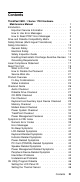
Hard Disk Drive Replacement Strategy: Always try to run a low-level format before replacing a hard disk drive. Attention The drive startup sequence in the computer you are servicing might have been changed. Be extremely careful during write operations such as copying, saving, or formatting. Data or programs can be overwritten if you select an incorrect drive. How to Use Error Messages Use the error codes displayed on the screen to diagnose failures.
Drive and Diskette Compatibility Matrix The following table provides identification information for 3.5-inch drives. Diskette Drive Identifying Mark 3.5-Inch - 1.44MB 3.5-Inch - 2.88MB 1.44 on the eject button 2.88 on the eject button The following table provides compatibility information for 3.5-inch diskettes and 3.5-inch diskette drives. Diskette Capacity 1.44MB Drive 2.88MB Drive 1.0MB 2.0MB 4.
Safety Notices (Multi-lingual Translations) In this manual, safety notices appear in English with a page number reference to the appropriate multi-lingual, translated safety notice found in this section. The following safety notices are provided in English, French, German, Italian, and Spanish languages. Safety Notice 1 Before the computer is powered-on after FRU replacement, make sure all screws, springs, or other small parts are in place and are not left loose inside the computer.
Safety Notice 2 Some standby batteries contain a small amount of nickel and cadmium. Do not disassemble it, recharge it, throw it into fire or water, or short-circuit it. Dispose of the battery as required by local ordinances or regulations. Use only the battery in the appropriate parts listing. Use of an incorrect battery can result in ignition or explosion of the battery. Certaines batteries de secours contiennent du nickel et du cadmium.
Safety Notice 3 The battery pack contains small amounts of nickel. Do not disassemble it, throw it into fire or water, or shortcircuit it. Dispose of the battery pack as required by local ordinances or regulations. Use only the battery in the appropriate parts listing when replacing the battery pack. Use of an incorrect battery can result in ignition or explosion of the battery. La batterie contient du nickel. Ne la démontez pas, ne l'exposez ni au feu ni à l'eau. Ne la mettez pas en court-circuit.
Safety Notice 4 The lithium battery can cause a fire, explosion, or severe burn. Do not recharge it, remove its polarized connector, disassemble it, heat it above 100°C (212°F), incinerate it, or expose its cell contents to water. Dispose of the battery as required by local ordinances or regulations. Use only the battery in the appropriate parts listing. Use of an incorrect battery can result in ignition or explosion of the battery. La pile de sauvegarde contient du lithium.
Safety Notice 5 If the LCD breaks and the fluid from inside the LCD gets into your eyes or on your hands, immediately wash the affected areas with water for at least 15 minutes. Seek medical care if any symptoms from the fluid are present after washing. Si le panneau d'affichage à cristaux liquides se brise et que vous recevez dans les yeux ou sur les mains une partie du fluide, rincez-les abondamment pendant au moins quinze minutes. Consultez un médecin si des symptômes persistent après le lavage.
Safety Notice 6 To avoid shock, do not remove the plastic cover that surrounds the lower portion of the inverter card. Afin d'éviter tout risque de choc électrique, ne retirez pas le cache en plastique protégeant la partie inférieure de la carte d'alimentation. Aus Sicherheitsgründen die Kunststoffabdeckung, die den unteren Teil der Spannungswandlerplatine umgibt, nicht entfernen. Per evitare scosse elettriche, non rimuovere la copertura in plastica che avvolge la parte inferiore della scheda invertitore.
Safety Notice 8 Before removing any FRU, power-off the computer, unplug all power cords from electrical outlets, remove the battery pack, then disconnect any interconnecting cables. Avant de retirer une unitˆ rempla†able en clientèle, mettez le système hors tension, débranchez tous les cordons d'alimentation des socles de prise de courant, retirez la batterie et déconnectez tous les cordons d'interface.
Safety Information The following section contains the safety information that you need to be familiar with before servicing an IBM mobile computer. General Safety Follow these rules to ensure general safety: Observe good housekeeping in the area of the machines during and after maintenance. When lifting any heavy object: 1. Ensure you can stand safely without slipping. 2. Distribute the weight of the object equally between your feet. 3. Use a slow lifting force.
Reinstall all covers correctly before returning the machine to the customer. Electrical Safety Observe the following rules when working on electrical equipment. Important Use only approved tools and test equipment. Some hand tools have handles covered with a soft material that does not insulate you when working with live electrical currents. Many customers have, near their equipment, rubber floor mats that contain small conductive fibers to decrease electrostatic discharges.
Observe the special safety precautions when you work with very high voltages; these instructions are in the safety sections of maintenance information. Use extreme care when measuring high voltages. Regularly inspect and maintain your electrical hand tools for safe operational condition. Do not use worn or broken tools and testers. Never assume that power has been disconnected from a circuit. First, check that it has been powered-off. Always look carefully for possible hazards in your work area.
Explosive hazards, such as a damaged CRT face or bulging capacitor. Mechanical hazards, such as loose or missing hardware. The guide consists of a series of steps presented in a checklist. Begin the checks with the power off, and the power cord disconnected. Checklist: 1. Check exterior covers for damage (loose, broken, or sharp edges). 2. Power-off the computer. Disconnect the power cord. 3. Check the power cord for: a. A third-wire ground connector in good condition.
Wear a grounded wrist strap against your skin to eliminate static on your body. Prevent the part from touching your clothing. Most clothing is insulative and retains a charge even when you are wearing a wrist strap. Use the black side of a grounded work mat to provide a static-free work surface. The mat is especially useful when handling ESD-sensitive devices. Select a grounding system, such as those listed below, to provide protection that meets the specific service requirement.
Laser Compliance Statement Some IBM Personal Computer models are equipped from the factory with a CD-ROM drive. CD-ROM drives are also sold separately as options. The CD-ROM drive is a laser product. The CD-ROM drive is certified in the U.S. to conform to the requirements of the Department of Health and Human Services 21 Code of Federal Regulations (DHHS 21 CFR) Subchapter J for Class 1 laser products.
puede provocar la exposición a radiaciones peligrosas. Opening the CD-ROM drive could result in exposure to hazardous laser radiation. There are no serviceable parts inside the CD-ROM drive. Do not open. Some CD-ROM drives contain an embedded Class 3A or Class 3B laser diode. Note the following. DANGER: Laser radiation when open. Do not stare into the beam, do not view directly with optical instruments, and avoid direct exposure to the beam. Radiação por raio laser ao abrir.
Read This First Before you go to the checkout guide, be sure to read this section. Important Notes Only certified trained personnel should service the computer. Read the entire FRU service procedures before replacing any FRUs. Use new nylon-coated screws when you replace FRUs. Be extremely careful during write operations such as copying, saving, or formatting. Drives in the computer that you are servicing might have been rearranged or the drive startup sequence might have been altered.
Before checking problems with the computer, determine whether or not the damage applies to the warranty by referring to the following: Note for Warranty: During the warranty period, the customer may be responsible for repair costs if the computer damage was caused by misuse, accident, modification, unsuitable physical or operating environment, or improper maintenance by the customer.
3. Remove the backup battery (RTC) for 20 minutes or use a screwdriver to touch the backup battery (RTC) for 1 second. 4. Put back the backup battery (RTC). 5. Power on the computer and wait until POST ends. 6. Verify that the password prompt does not appear. Supervisor and HDD passwords: The Supervisor password and Hard Disk password (Hard Disk1 and Hard Disk2) are security features that are used to protect the system and the hard disk drive data from unauthorized access.
Product Overview The following shows an overview of the system features of the ThinkPad 390X / i Series 1700 computer. Feature Processor Description Intel Mobile Pentium III processor 500 MHz, L2 cache Intel Mobile Pentium III processor 450 MHz, L2 cache Intel Mobile Pentium II processor 400 MHz, L2 cache Intel Mobile Celeron processor 400 MHz, L2 cache Bus architecture PCI Bus Memory 2 DIMM slots, no memory on the system board 32 MB, 64 MB, 128 MB, or 256 MB DIMM card (max.
Feature Description PC Card (PCMCIA) One Type III or two Type II AC Adapter 56–Watt type CardBus, ZV port support Fn Key Combinations The following table shows the Fn key and function key combinations and their corresponding functions. The Fn key works independently of the operating system. The operating system obtains the status through the system management interface to control the system.
Status Indicators The system status LED indicators show the current computer status. The following shows the location of each indicator symbol and the meaning of each indicator. Symbol Color Meaning (1) Battery status Green Enough battery power remains for operation. Blinking orange The battery pack needs to be charged Orange The battery pack is being charged. Green The computer is in suspend mode. Blinking green The computer is entering suspend mode.
Symbol Color Meaning (5) Caps lock Green Caps Lock mode is enabled. All alphabetic characters (A-Z) are entered in capital letters without the Shift key being pressed. You enable or disable the Caps Lock mode by pressing the Caps Lock key. (6) Scroll lock Green Scroll Lock mode is enabled. The Arrow keys can be used as screen-scroll function keys. The cursor cannot be moved with the Arrow keys. Not all application programs support this function.
Checkout Guide Use the following procedure as a guide for computer problems. Besides the checkout tests described in this section, there are other items you can test for using the PC-Doctor DOS diagnostics program. See “PC-Doctor DOS System Diagnostics” on page 48 for details. Note: The diagnostic tests are intended to test only IBM products. Non-IBM products, prototype cards, or modified options can give false errors and invalid system responses. 1.
Audio Checkout Do as follows: 1. Boot from and start PC-Doctor DOS. (See “PC-Doctor DOS System Diagnostics” on page 48 for details.) 2. Select Interactive Tests. 3. Select Internal Speaker. If no sound is played, replace the speaker or the system board. 4. Select Stereo Speaker. If no music is played, replace the speaker or the system board. Diskette Drive Checkout Do the following to isolate the problem to a controller, drive, or diskette.
CD-ROM Checkout Do the following to isolate the problem to a controller, drive, or CD-ROM. Make sure that the CD-ROM disc does not have any label attached to it. The label can cause damage to the drive or can cause the drive to fail. Do the following to select the test device: 1. Boot from and start PC-Doctor DOS. (See “PC-Doctor DOS System Diagnostics” on page 48 for details.) 2. Select Interactive Tests. 3. Select CD-ROM/DVD Test. 4. Follow the instructions in the message window.
Keyboard and Auxiliary Input Device Checkout Note: Remove the external keyboard if the internal keyboard is to be tested. If the internal keyboard does not work or an unexpected character appears, make sure that the flexible cable extending from the keyboard is correctly seated in the connector. If the keyboard cable connection is correct, run the Keyboard Test. 1. Boot from and start PC-Doctor DOS. (See “PC-Doctor DOS System Diagnostics” on page 48 for details.) 2. Select Interactive Tests. 3.
Memory Checkout DIMM are available for increasing memory capacity. Slot 1 (MB) Slot 2 (MB) Total Memory (MB) 32 0 32 0 32 32 32 32 64 64 0 64 0 64 64 64 32 96 32 64 96 64 64 128 128 0 128 0 128 128 128 32 160 32 128 160 128 64 192 64 128 192 128 128 256 Memory errors might stop system operation, show error messages on the screen, or hang the system. Use the following procedure to isolate memory problems: 1. Boot from and start PC-Doctor DOS.
Modem Board Checkout Do the following to isolate the problem to the system internal modem: 1. Boot from and start PC-Doctor DOS. (See “PC-Doctor DOS System Diagnostics” on page 48 for details.) 2. Select Diagnostics. 3. Select Other Devices. 4. Run Modem Loopback Test and Modem Dialtone/DTMF Test. 5. Follow the instructions in the message window. 6. If the test detects a modem problem, replace the modem card.
Power System Checkout To verify the symptom of the problem power on the computer using each of the following power sources: 1. Remove the battery. 2. Connect the AC Adapter and check that power is supplied. 3. Disconnect the AC Adapter and install the charged battery; then check that power is supplied by the battery.
Checking the Operational Charging: To check operational charging, use a discharged battery pack or a Battery that has less than 50% of the total power remaining when installed in the computer. Perform operational charging. If the battery status indicator does not turn on, remove the Battery and let it return to room temperature. Reinstall the Battery. If the charge indicator still does not turn on, replace the Battery.
TrackPoint Checkout If the external mouse is connected, the TrackPoint does not work. In this case, please detach the external mouse to check the TrackPoint. If this does not correct the TrackPoint problem, continue with the following. After you use the TrackPoint, the pointer drifts on the screen for a short time. This self-acting pointer movement can occur when a slight, steady pressure is applied to the TrackPoint pointer. This symptom is not a hardware problem.
Power Management Features Three power management modes are available in the computer system to reduce power consumption and to prolong battery life. Standby Mode: In standby mode, the following occurs: The LCD backlight turns off. The audio amplifier turns off. (Fn+F3) Events that cause the computer to enter standby mode: Standby mode requested by the Fn key (Fn+F3). The computer exits standby and resumes operation when any key is pressed.
The computer also exits suspend mode when timer conditions are satisfied for entering hibernation mode. Hibernation Mode: For Windows NT or OS/2 user: A Windows NT or OS/2 user cannot create a hibernation file in a Windows NT or OS/2 system that uses the NTFS/HPFS format system. If you want to use hibernation mode, you should reinstall Windows NT with a FAT format system. Also, if boot manager is installed, the computer cannot enter hibernation mode.
How to Create the Hibernation Function: Do as follows: Start the ThinkPad Configuration program. Click on the Power Management icon. Click on the Hibernation Options tab. Click on Enable Hibernation. Click on OK. Note: If you change the memory size, you need to recreate the hibernation file or partition. For partition-based hibernation, use the hibernation utility to delete the partition first before creating a new one.
Symptom-to-FRU Index The Symptom-to-FRU Index lists the symptoms and errors and the possible causes. The most likely cause is listed first. Note: Perform the FRU replacement or actions in the sequence shown in the FRU/Action columns. If a FRU replacement does not solve the problem, put the original part back in the computer. Do not replace a non-defective FRU. This index can also be used to help you decide the next possible FRUs to be replaced when servicing a computer.
Numeric Error Codes The following is a list of the message that the BIOS can display. Most of them occur during POST. Some of them display information about a hardware device, e.g., the amount of memory installed. Others may indicate a problem with a device, such as the way it has been configured. Following the list are explanations of the messages and remedies for reported problems.
Symptom/Error 0281 Memory size found by POST differed from CMOS 02Bx Diskette drive A error FRU/Action in Sequence 1. Load Setup Defaults in the BIOS Setup Utility. 2. DIMM 3. System board 1. Check that the drive is defined with the proper diskette type in BIOS Setup Utility. 2. Go to “Diskette Drive Checkout” on page 27. 02D0 1. CPU card System cache error — Cache disabled 2.
Error Messages Symptom/Error Device Address Conflict FRU/Action in Sequence 1. Load Setup Defaults in BIOS Setup Utility. 2. Backup battery (RTC) 3. System board Allocation Error for: device 1. Load Setup Defaults in BIOS Setup Utility. 2. Backup battery (RTC) 3. System board Failing Bits: nnnn 1. DIMM 2. BIOS ROM 3. System board Invalid System Configuration Data 1. Load Setup Defaults in BIOS Setup Utility. 2. BIOS ROM 3. System board I/O device IRQ conflict 1.
Symptom/Error No beep, power-on indicator off, LCD blank during POST No beep, power-on indicator on, LCD blank during POST No beep during POST but system runs correctly. FRU/Action in Sequence Battery AC Adapter DC-DC & BATT board System board Reseat DIMM. CPU card System board Speaker LCD-Related Symptoms Symptom/Error FRU/Action in Sequence LCD backlight not working 1. Reseat the LCD connector. LCD too dark 3. LCD FPC LCD brightness cannot be adjusted 4.
Power-Related Symptoms Symptom/Error Power shuts down during operation. FRU/Action in Sequence 1. Battery 2. AC Adapter 3. DC/DC & Charger board 4. System board The system will not power on. 1. Battery 2. AC Adapter 3. DC/DC & Charger board 4. System board The system will not power off. 1. Press and hold the power switch for more than 4 seconds 2. DC/DC & Charger board 3. System board Battery can't be charged.
Symptom/Error The system will not wake up from hibernation mode. FRU/Action in Sequence 1. Keyboard (if control is from the keyboard) 2. Hard disk drive 3. System board The system will not enter suspend mode after closing the LCD. 1. Lid switch Battery fuel-gauge does not go higher than 90%. 1. Remove Battery and let it cool for 2 hours. 2. System board 2. Refresh battery (continue using battery in BIOS Setup mode until power off, then charge battery). 3. Battery 4. DC/DC & Charger board 5.
When analyzing an intermittent problem, do the following: 1. Run the advanced diagnostic test for the system board in loop mode at least 10 times. 2. If no error is detected, do not replace any FRUs. 3. If any error is detected, replace the FRU shown by the FRU code.. Rerun the test to verify that no more errors exist.
CE Utility Program Diskette Note: You can download the CE Utility Program Diskette from the IBM website. Setting the LCD Panel ID There is an EEPROM in the inverter which stores its supported LCD type ID code. If you replace a LCD with one of a different brand or use a new inverter, the ID information in the inverter EEPROM should be updated. Follow the steps below to set the LCD Panel ID: 1. Boot from the Utility Program Diskette. 2. Select LCD Panel ID Utility from PC DOS 7.0 Startup Menu. 3.
Writing the RFID Data The EEPROM on the system board contains the system unit serial number and the system board serial number. When you replace the system board, restore the system unit serial number using the RFID Utility in the ThinkPad CE Utility Diskette. The serial number label is attached to the computer.
Running the Diagnostics PC-Doctor DOS is used to perform diagnostics on the ThinkPad 390X / i Series 1700.
To use PC-Doctor DOS: 1. Press the left and right arrow keys to move around the main menu. Press Enter to enable the highlighted option. The main options are: Diagnostics Interactive Tests Hardware Info Utility Quit 2. Press the up and down arrow keys to move in a selected menu. Press Enter to enable the highlighted option. Note: You can press F1 for help. The Diagnostics and Interactive Tests menus contain test items you perform on the computer.
PC-Doctor DOS Diagnostics Error Codes and Messages: The following table does not include user-initiated aborts, which display the error type 195.
Error Code 5-16 to 15-36 Error Code Test(s) Message 5-16 Video Memory pattern failed 5-24 Video Video page test failed 5-26 Video Register failed 5-199 Video Could not initialize mode 13H for register test 11-2 COM Timeout sending 11-13 COM LCR/MCR fail 11-14 COM Internal loopback 11-15 COM External loopback 11-40 COM No interrupt detected 11-197 COM No FIFO part (can't run FIFO test) IR mode enabled (can't run serial test) No external loopback adapter (if prompt times out)
Error Code 18-1 to 18-27 Error Code Test(s) Message 18-1 PCMCIA No PCMCIA detected 18-5 PCMCIA Incorrect PCMCIA version 18-9 PCMCIA Incorrect number of sockets 18-24 PCMCIA Index register failed 18-27 PCMCIA Socket configuration read error FRU/Action in Sequence: PCMCIA holder System board Error Code 20-1 to 71-41 Error Code Test(s) Message 20-1 PCI No PCI detected 20-5 PCI Incorrect PCI BIOS version 20-27 PCI Problem reading PCI configuration 20-196 PCI Too many PCI
Error Code 75-1 Error Code Test(s) Message 75-1 AC CHARGER AC Charger not supported FRU/Action in Sequence: DC-DC & BATT board System board Error Code 89-250 to 89-294 Error Code Test(s) Message 89-250 CPU Math coprocessor 89-266 CPU Registers 89-278 CPU Arithmetics 89-282 CPU Logical ops 89-286 CPU String ops 89-294 CPU Exceptions MMX FRU/Action in Sequence: Reload BIOS default setting CPU card System board Error Code 170-1 to 175-198 Error Code Test(s) Mes
Error Code 175-199 Error Code Test(s) Message 175-199 FAN Fan test failed FRU/Action in Sequence: Fan System board Error Code 175-250 to 185-262 Error Code Test(s) Message 175-250 LM75/ Max1617 Interrupt condition detected 185-1 RFID/ ALERTPACK Asset ID not supported SMBUS not detected (if not required) AlertPack not supported AlertPack not detected (if not required) 185-2 ALERTPACK Transmission timeout 185-5 ALERTPACK Invalid revision 185-9 RFID/ ALERTPACK SMBUS not detected
Error Code 201-1 to 201-198 Error Code Test(s) Message 201-1 DIMM No SMBus detected (iFailNoSmbus=1) No DIMMs detected (iFailNoDimms=1) 201-13 DIMM EEPROM write protect failed (iFailEpWr=1) 201-25 DIMM Bad EEPROM checksum 201-198 DIMM No SMBus detected (iFailNoSmbus=0) FRU/Action in Sequence: DIMM System board Error Code 202-1 to 202-18 Error Code Test(s) Message 202-1 CACHE CPU not in correct mode for test 202-3 CACHE NMI detected during cache test 202-18 CACHE Cache faile
Error Code 215-1 to 215-254 Error Code Test(s) Message 215-1 CDROM No drive or MSCDEX driver detected 215-196 CDROM Too many errors 215-254 CDROM Sector read failed FRU/Action in Sequence: Reseat CD-ROM cable CD-ROM drive System board Error Code 217-14 to 217-262 Error Code Test(s) Message 217-14 HD Controller data loop 217-32 HD Inquiry data change between reads 217-195 HD User abort 217-198 HD No drive parameters readable Testing parameters out of range 217-250 HD
Error Code 304-1 to 304-199 Error Code Test(s) Message 304–1 BATTERY No battery installed No battery detected 304–199 BATTERY General battery failure FRU/Action in Sequence: Battery pack DC-DC & BATT board System board Error Code 415-1 to 415-250 Error Code Test(s) Message 415-1 MODEM PnP ISA modem detected but not enabled PCI modem detected but not enabled Modem not detected 415-250 COM/Modem Modem ATZ No dialtone detected FRU/Action in Sequence: Reseat Modem card Modem
FRU Removals and Replacements This section contains information about removals and replacements. Do not damage any parts. Only certified and trained personnel should service the computer. The arrows in this section show the direction of movement to remove a FRU, or to turn a screw to release the FRU. The arrows are marked in numeric order, in square callout, to show the correct sequence of removal.
FRU Service Procedures Review the following procedures before replacing any FRU. LCD FRU Replacement Notice: The TFT LCD for the notebook computer contains over 2,359,296 thinfilm transistors (TFTs). A small number of missing, discolored, or lighted dots (on all the time) is characteristic of TFT LCD technology, but excessive pixel problems can cause viewing concerns. The LCD should be replaced if the number of missing, discolored, or lighted dots in any background is: SVGA (12.
Torque driver If you have a torque driver, refer to the "Torque" column with each step. Make sure you use the correct screw, and tighten all screws firmly to the torque shown in the table if you have a torque screwdriver. Never use a screw that you removed. Use a new one. Make sure the screws are tightened firmly. Important Notice This computer uses special nylon-coated screws with the following characteristics: They maintain tight connections.
Battery To remove the Battery, press the latch to release, then pull out the Battery. 1 2 3 Reverse the steps described above when installing a new battery pack.
Hard Disk Drive Warning Do not drop or apply any shock to the hard disk drive. The hard disk drive is sensitive to physical shock. Incorrect handling can cause damage and permanent loss of data on the drive. Before removing the drive, have the user make a backup copy of all the information on the drive if possible. Never remove the drive while the system is operating or is in suspend mode. To remove the hard disk drive: 1. Use a coin to unscrew the hard disk drive screw.
Combo Bay To remove the Combo Bay, press and hold the lock to release, then slide out the Combo Bay module to remove.
Diskette Drive To remove the Diskette Drive: 1. Remove the four screws securing the Diskette Drive as shown. 2. Disconnect the Diskette Drive cable from the connector. Note: Lift both sides of the connector. 3. Slide out the Diskette Drive to remove. Step 1 Size (Quantity) Head & Color M2.5 x 3.5L (3) Flat head, black Torque 1.6 kgf-cm Note: Make sure you use the correct screw for replacement.
CD-ROM To remove the CD-ROM: 1. Remove the four screws securing the CD-ROM. 2. Carefully slide out the CD-ROM to remove. Note: Watch out for the sharp edges on the CD-ROM. Step Size (Quantity) Head & Color 1 M2.5x 4L (4) Flat head, silver Torque 1.6 kgf-cm Note: Make sure you use the correct screw for replacement.
Combo Bay FPC To remove the Combo Bay FPC: 1. Remove the two screws securing the Combo Bay FPC. 2. Carefully disconnect the Combo Bay FPC from the connector. 2 1 Step 1 Size (Quantity) Head & Color M2.5x 3.5L (2) Flat head, black Torque 1.6 kgf-cm Note: Make sure you use the correct screw for replacement.
Hard Disk Adapter Combo Bay To remove the second hard disk drive from the hard disk drive adapter: 1. Remove the two screws of the Combo Bay adapter. 2. Slide the hard disk drive out and up to remove. Step Size (Quantity) Head & Color 1 M3 x 5L (2) Pan head, black Torque 1.6 kgf-cm Note: Make sure you use the correct screw for replacement.
Modem Card “Battery” on page 61 Note: Never remove or attach the card before removing the Battery. To remove the modem card: 1. Use a flat-bladed screwdriver to remove the screw on the modem door. 1 2. Carefully release the latches on both sides of the modem card. 3. Gently pull out the cable from the connector to remove the modem card. Step Size (Quantity) Head & Color 1 M2.5 x 5L (1) Flat head, black Torque 2.0kgf-cm Note: The screws do not separate from the modem board cover.
Backup Battery (RTC) “Battery” on page 61 “Modem Card” on page 68 Safety Notice 4: Translation on page 8 The lithium battery can cause a fire, explosion, or severe burn. Do not recharge it, remove its polarized connector, disassemble it, heat it above 100°C (212°F), incinerate it, or expose its cell contents to water. Dispose the battery as required by local ordinances or regulations. Use only the battery in the appropriate parts listing.
Keyboard “Battery” on page 61 “Hard Disk Drive” on page 62 To remove the keyboard: 1. Use a 1/8" alignment tool to release the latches to lift the middle cover away. 2. Remove the two screws securing the keyboard. Step Size (Quantity) Head & Color 3 M2 x 4L (2) Flat head, silver Torque 1.6 kgf-cm Note: Make sure you use the correct screw for replacement. 3. Carefully lift the keyboard up to expose the keyboard connector. Note: Be careful of the keyboard cable as it is fragile.
4. Use a flat-bladed screwdriver to release the cable from the connector. 5. Remove the keyboard from the lower case.
LED Board “Battery” on page 61 “Hard Disk Drive” on page 62 “Keyboard” on page 70 To remove the LED board: 1. Remove the screw securing the LED board then disconnect the LED cable from the connector. 2. Lift the LED board. 2 3 1 Step Size (Quantity) Head & Color 2 M2 x 4L (1) Flat head, silver Torque 1.6 kgf-cm Note: Make sure you use the correct screw for replacement.
Upper Heatsink “Battery” on page 61 “Hard Disk Drive” on page 62 “Keyboard” on page 70 1 2 3 Size (Quantity) Head & Color 1 M2.5 x 18L (3) Pan head, black 2.0 kgf-cm 2 M2 x 18L (3) Pan head, black 2.0 kgf-cm 3 M2 x 4L (4) Flat head, silver 1.6 kgf-cm Step Torque Note: Make sure you use the correct screw for replacement.
PCMCIA Slots “Battery” on page 61 “Hard Disk Drive” on page 62 “Keyboard” on page 70 “Upper Heatsink” on page 73 To remove the PCMCIA slots: 1. Remove the three screws securing the PCMCIA slot board. 2 1 Step Size (Quantity) Head & Color 1 M2 x 18L (2) Pan head, black 2.0 kgf-cm 2 M2 x 14L (2) Flat head, silver 2.0 kgf-cm Torque Note: Make sure you use the correct screw for replacement. 2. Use a flat-bladed screwdriver to disconnect the PCMCIA card from the connector.
CAUTION: When reassembling this section of the machine, the upper heatsink must be reassembled first before the PCMCIA slots.
CPU Board “Battery” on page 61 “Hard Disk Drive” on page 62 “Keyboard” on page 70 Use the special tool to remove the CPU board. Note: The CPU tool is for depot use only. 2 1 To install the CPU board. Note: When you replace the CPU board, press only on the places indicated in the figure. Press both sides at the same time. Do not press only one side or any other part of the board.
LCD Panel “Battery” on page 61 “Hard Disk Drive” on page 62 “Keyboard” on page 70 To remove the LCD Panel: 1. Remove the two screws securing the LCD FPC cable. 2. Remove the LCD FPC cable. Then: Disconnect the LCD FPC cable from the lower case (12.1"). Disconnect the LCD FPC cable and LVDS board (15.0" and 14.1"). 3. Turn the notebook over; then remove four screws securing the LCD Panel as shown. 4. Pull out the LCD Panel. 12.1” 4 1 2 15.0”/14.
Step 2 3 Size (Quantity) Head & Color Torque M2.5 x 18L (1) Pan head, black 15.1" and 14.1" M2 x 10L (1) Pan head, silver L:1.6 kgf-cm Flat head, black 4.0 kgf-cm M2.5 x 6L (4) R:1.6 kgf-cm Note: Make sure you use the correct screw for replacement.
Upper Cover “Battery” on page 61 “Hard Disk Drive” on page 62 “Combo Bay” on page 63 “Keyboard” on page 70 “LED Board” on page 72 “Upper Heatsink” on page 73 “LCD Panel” on page 77 To remove the upper case: 1. Remove the screws from the upper cover. 2 1 Step Size (Quantity) Head & Color 1 M2 x 4L (1) Flat head, silver 1.6 kgf-cm 2 M2 x 18L (3) Pan head, black 1.6 kgf-cm Torque Note: Make sure you use the correct screw for replacement. 2. Turn the notebook over.
Step 3 Size (Quantity) Head & Color M2.5 x 18L (3) Pan head, black Torque 2.0 kgf-cm Note: Make sure you use the correct screw for replacement. 3. Use a flat-bladed screwdriver to remove the latch. 4. Disconnect the cable from the main unit. Now you can remove the upper cover from the base cover.
IMM Lower Heatsink “Battery” on page 61 “Hard Disk Drive” on page 62 “Combo Bay” on page 63 “Keyboard” on page 70 “LED Board” on page 72 “Upper Heatsink” on page 73 “CPU Board” on page 76 “LCD Panel” on page 77 “Upper Cover” on page 79 To remove the IMM lower heatsink: 1. Disconnect the fan cable from the connector. 2. Remove the screw securing the IMM lower heatsink. Lift the IMM lower heatsink up to remove.
Fan “Battery” on page 61 “Hard Disk Drive” on page 62 “Combo Bay” on page 63 “Keyboard” on page 70 “LED Board” on page 72 “Upper Heatsink” on page 73 “CPU Board” on page 76 “LCD Panel” on page 77 “Upper Cover” on page 79 “IMM Lower Heatsink” on page 81 Remove the screw securing the fan. Lift the fan up to remove. 1 Step Size (Quantity) Head & Color 1 M2 x 4L (1) Flat head, silver Torque 1.6 kgf-cm Note: Make sure you use the correct screw for replacement.
Speakers Note: This section is only for 15.0–inch LCD models.
Step Size (Quantity) Head & Color 1 M2.5 x 6L (4) Flat head, black Torque 2.0 kgf-cm Note: Make sure you use the correct screw for replacement.
Power Latch, IR Board, and DC-DC & BATT Board “Battery” on page 61 “Hard Disk Drive” on page 62 “Combo Bay” on page 63 “Keyboard” on page 70 “LED Board” on page 72 “Upper Heatsink” on page 73 “CPU Board” on page 76 “LCD Panel” on page 77 “Upper Cover” on page 79 “IMM Lower Heatsink” on page 81 “Fan” on page 82 To remove these boards and latch: 1. Remove the power latch. 2. Remove the IR board. 3.
System Board “Battery” on page 61 “Hard Disk Drive” on page 62 “Combo Bay” on page 63 “Keyboard” on page 70 “LED Board” on page 72 “Upper Heatsink” on page 73 “CPU Board” on page 76 “LCD Panel” on page 77 “Upper Cover” on page 79 “IMM Lower Heatsink” on page 81 “Fan” on page 82 “Speakers” on page 83 Note: Only for 15.0–inch LCD models. “Power Latch, IR Board, and DC-DC & BATT Board” on page 85 Note: See “Replacing the System Board” on page 59 before proceeding.
Combo Bay Interposer Board “Battery” on page 61 “Hard Disk Drive” on page 62 “Combo Bay” on page 63 “Keyboard” on page 70 “LED Board” on page 72 “Upper Heatsink” on page 73 “CPU Board” on page 76 “LCD Panel” on page 77 “Upper Cover” on page 79 “IMM Lower Heatsink” on page 81 “Fan” on page 82 “Power Latch, IR Board, and DC-DC & BATT Board” on page 85 “System Board” on page 86 Disconnect the Combo Bay Interposer Board from the system board.
LCD Bezel 15.0" “Battery” on page 61 “Hard Disk Drive” on page 62 “Combo Bay” on page 63 “Keyboard” on page 70 Step Size (Quantity) Head & Color 1 M2.5 x 6L (3) Flat head, black Torque 2.0 kgf-cm Note: Make sure you use the correct screw for replacement.
LCD Inverter 15.0" “Battery” on page 61 “Hard Disk Drive” on page 62 “Combo Bay” on page 63 “Keyboard” on page 70 “LCD Bezel 15.0"” on page 88 Note: See “Setting the LCD Panel ID” on page 46. Step Size (Quantity) Head & Color 1 M2 x 4L (1) Flat head, silver Torque 1.6 kgf-cm Note: Make sure you use the correct screw for replacement.
Microphone 15.0" “Battery” on page 61 “Hard Disk Drive” on page 62 “Combo Bay” on page 63 “Keyboard” on page 70 “LCD Bezel 15.0"” on page 88 “LCD Inverter 15.
LCD Panel 15.0" “Battery” on page 61 “Hard Disk Drive” on page 62 “Combo Bay” on page 63 “Keyboard” on page 70 “LCD Bezel 15.0"” on page 88 “LCD Inverter 15.0"” on page 89 “Microphone 15.0"” on page 90 1 Step Size (Quantity) Head & Color M2.5 x 4L (4) Flat head, black Torque 2.0 kgf-cm Note: Make sure you use the correct screw for replacement.
Step Size (Quantity) Head & Color M2 x 4L (6) Flat head, silver Torque 1.6 kgf-cm Note: Make sure you use the correct screw for replacement.
LCD Bezel 14.1" “Battery” on page 61 “Hard Disk Drive” on page 62 “Combo Bay” on page 63 “Keyboard” on page 70 Remove the three screws securing the LCD bezel. Step Size (Quantity) Head & Color 2 M2.5 x 6L (3) Pan head, black Torque 2.0 kgf-cm Note: Make sure you use the correct screw for replacement.
Speaker 14.1" “Battery” on page 61 “Hard Disk Drive” on page 62 “Combo Bay” on page 63 “Keyboard” on page 70 “LCD Bezel 14.1"” on page 93 To remove the speaker: 1. Carefully disconnect the speaker cable from the connector. 2. Remove the five screws securing the speaker. 3. Gently lift the speaker away from the display panel. Step Size (Quantity) Head & Color 2 M2 x 4L (5) Flat head, silver Torque 1.6 kgf-cm Note: Make sure you use the correct screw for replacement.
VR Board 14.1" “Battery” on page 61 “Hard Disk Drive” on page 62 “Combo Bay” on page 63 “Keyboard” on page 70 “LCD Bezel 14.1"” on page 93 “Speaker 14.1"” on page 94 To remove the VR board: 1. Disconnect the power cable from the VR board. 2. Carefully remove the VR board from the display panel.
Microphone 14.1" “Battery” on page 61 “Hard Disk Drive” on page 62 “Combo Bay” on page 63 “Keyboard” on page 70 “LCD Bezel 14.1"” on page 93 “Speaker 14.1"” on page 94 “VR Board 14.1"” on page 95 To remove the microphone: 1. Disconnect the power cable from the microphone. 2. Lift the LCD away from the display panel.
LCD Panel 14.1" “Battery” on page 61 “Hard Disk Drive” on page 62 “Combo Bay” on page 63 “Keyboard” on page 70 “LCD Bezel 14.1"” on page 93 “Speaker 14.1"” on page 94 “VR Board 14.1"” on page 95 “Microphone 14.1"” on page 96 Remove the screw covers and screws. Step Size (Quantity) Head & Color M2 x 4L (2) Flat head, silver Torque 1.6 kgf-cm Note: Make sure you use the correct screw for replacement.
LCD Inverter 14.1" “Battery” on page 61 “Hard Disk Drive” on page 62 “Combo Bay” on page 63 “Keyboard” on page 70 “LCD Bezel 14.1"” on page 93 “Speaker 14.1"” on page 94 “VR Board 14.1"” on page 95 “Microphone 14.1"” on page 96 “LCD Panel 14.1"” on page 97 Note: See “Setting the LCD Panel ID” on page 46. To remove the LCD inverter: 1. Disconnect the cable from the inverter board. 2. Lift the inverter board away from the display panel.
LCD FPC 14.1" “Battery” on page 61 “Hard Disk Drive” on page 62 “Combo Bay” on page 63 “Keyboard” on page 70 “LCD Bezel 14.1"” on page 93 “Speaker 14.1"” on page 94 “VR Board 14.1"” on page 95 “Microphone 14.1"” on page 96 “LCD Panel 14.1"” on page 97 Disconnect the LCD FPC cable from the LCD. Note: The LCD FPC cable has a double-sided adhesive tape attached on its back side. Two current black tapes (LCD FPC Stopper Tape) must be applied to this cable.
LCD Bezel 12.1" “Battery” on page 61 “Hard Disk Drive” on page 62 “Combo Bay” on page 63 “Keyboard” on page 70 Remove the three screws securing the LCD bezel. Step Size (Quantity) Head & Color 2 M2.5 x 6L (3) Flat head, black Torque 2.0 kgf-cm Note: Make sure you use the correct screw for replacement.
Speaker 12.1" “Battery” on page 61 “Hard Disk Drive” on page 62 “Combo Bay” on page 63 “Keyboard” on page 70 “LCD Bezel 12.1"” on page 100 To remove the speaker: 1. Carefully disconnect the speaker cable from the connector. 2. Remove the five screws securing the speaker. 3. Gently lift the speaker away from the display panel. Step Size (Quantity) Head & Color 2 M2 x 4L (5) Flat head, silver Torque 1.6 kgf-cm Note: Make sure you use the correct screw for replacement.
VR Board 12.1" “Battery” on page 61 “Hard Disk Drive” on page 62 “Combo Bay” on page 63 “Keyboard” on page 70 “LCD Bezel 12.1"” on page 100 “Speaker 12.1"” on page 101 To remove the VR board: 1. Disconnect the power cable from the VR board. 2. Carefully remove the VR board from the display panel. Step Size (Quantity) Head & Color 2 M2 x 4L (1) Flat head, silver Torque 1.6 kgf-cm Note: Make sure you use the correct screw for replacement.
LCD Inverter 12.1" “Battery” on page 61 “Hard Disk Drive” on page 62 “Combo Bay” on page 63 “Keyboard” on page 70 “LCD Bezel 12.1"” on page 100 “Speaker 12.1"” on page 101 “VR Board 12.1"” on page 102 Note: See “Setting the LCD Panel ID” on page 46. To remove the LCD inverter: 1. Disconnect the cable from the inverter board. 2. Lift the inverter board away from the display panel.
Microphone 12.1" “Battery” on page 61 “Hard Disk Drive” on page 62 “Combo Bay” on page 63 “Keyboard” on page 70 “LCD Bezel 12.1"” on page 100 “Speaker 12.1"” on page 101 “VR Board 12.1"” on page 102 “LCD Inverter 12.1"” on page 103 To remove the microphone: 1. Disconnect the power cable from the microphone. 2. Lift the LCD away from the display panel.
LCD Panel 12.1" “Battery” on page 61 “Hard Disk Drive” on page 62 “Combo Bay” on page 63 “Keyboard” on page 70 “LCD Bezel 12.1"” on page 100 “Speaker 12.1"” on page 101 “VR Board 12.1"” on page 102 “LCD Inverter 12.1"” on page 103 “Microphone 12.1"” on page 104 Step Size (Quantity) Head & Color 2 M3 x 5L (4) Flat head, silver Torque 3.2 kgf-cm Note: Make sure you use the correct screw for replacement.
LCD FPC 12.1" “Battery” on page 61 “Hard Disk Drive” on page 62 “Combo Bay” on page 63 “Keyboard” on page 70 “LCD Bezel 12.1"” on page 100 “Speaker 12.1"” on page 101 “VR Board 12.1"” on page 102 “LCD Inverter 12.1"” on page 103 “Microphone 12.1"” on page 104 “LCD Panel 12.1"” on page 105 Disconnect the LCD FPC cable from the LCD.
System Unit Parts Listing 1 2 6 3 8 4 5 10 7 11 9 5 12 13 14 15 26 16 27 17 18 28 29 30 31 19-1 19 25 24 23 20 20-1 21 22 ThinkPad 390X / i 1700 HMM 107
Index Description FRU Number 1 Middle Cover 05K5481 2 LED Board W/ Cable 10L1154 3 See Keyboard list 4 Upper Heatsink For Celeron And Pentium II 10L1930 5 CPU Card (MMC-II, Celeron-400) 10L1439 CPU Card (MMC-II, Pentium II–400) 10L1440 CPU Card (MMC-II, Pentium III–450) 10L1354 CPU Card (MMC-II, Pentium III–500) 10L1355 6 PCMCIA Holder 05K5476 7 Upper Cover 12.1" 05K5478 Upper Cover 14.1" 05K5946 Upper Cover 15.
Index Description FRU Number Battery (NiMH) (Panasonic) 02K6521 20-1 Battery Slider Cover 05K5942 21 32MB DIMM SDRAM (PC-100) 08K3408 64MB DIMM SDRAM (PC-100) 08K3409 22 DIMM Door 05K5484 23 RTC 11J8591 24 PCI Modem Card 10L1296 Ethernet Card 10L1437 25 Modem Door 08K5836 26 Combo CD-ROM + FDD 05K9248 27 Diskette Drive 27L3529 28 CD-ROM (Toshiba) 05K9191 CD-ROM (LG) 05K9249 DVD Module 08K9163 29 Combo Bay Bracket 05K6155 30 Combo Bay FPC Kit 05K2819 31 Speaker
Index Description FRU Number KBD Turkish 02K4721 KBD Arabic 02K4722 KBD Russian 02K4723 KBD Slovakian 02K4724 KBD Slovenian 02K4725 KBD Hungarian 02K4726 KBD Czech 02K4727 KBD Japanese 02K4728 KBD Traditional Chinese 02K4729 KBD Korean 02K4730 KBD LA Spanish 02K4731 Miscellaneous Misc Name Plate Label Pack 05K5921 Rubber Kit 05K6176 FPC Stopper Tape 05K5914 Mylar Pack 05K5982 Screw Pack 05K5489 Screw M2*4 Wafer NI Screw M2*3E Stainless BT Screw M2*18 Pan B-ZN
Index Description FRU Number Power cord (Bahamas, Barbados, Bermuda, Bolivia, Canada, Cayman Islands, Colombia, Costa Rica, Dominican Republic, Ecuador, El Salvador, Guatemala, Guyana, Haiti, Honduras,Jamaica, Korea (South), Mexico, Netherlands, Antilles, Nicaragua, Panama, Peru, Philippines, Saudi Arabia, Suriname, Taiwan, Trinidad (West Indies), U.S.A.
LCD Unit Parts Listing 112 ThinkPad 390X / i 1700 HMM
12.1" LCD Parts Listing 1 2 3 4 5 6 7 8 9 10 11 Index System Unit FRU Number 1 LCD Bezel (12.1" TFT) 05K5469 2 Microphone W/ Holder 05K5477 3 Cable For Spk/Mic/VR Board 05K2818 4 Speaker (12.1"/13.3") 05K5467 5 VR Board (12.1"/13.3") 30L2576 6 LCD Inverter (12.1" TFT) 10L1645 7 LCD Panel (12.1" TFT) 08K5844 8 LCD FPC (12.1" TFT) 27L0493 9 LCD Rear Cover (12.1" TFT) 08K5845 10 Hinge Cap L,R (12.1"/13.3") 05K5466 11 Hinge L,R (12.1"/13.
Index 114 System Unit FRU Number LG/IBM Logo Kit 05K6044 ThinkPad 390X / i 1700 HMM
14.1" LCD Parts Listing 1 2 3 4 5 6 7 8 12 9 10 11 Index System Unit FRU Number 1 LCD Bezel (14.1" TFT) 05K5945 2 Microphone W/ Holder 05K5477 3 Cable For Spk/Mic/VR Board 05K2818 4 Speaker (14.1") 02K4869 5 LCD Panel (14.1" TFT) 05K9538 6 Hinge L,R (14.1") 05K5947 7 Hinge Cap L,R (14.1") 05K5948 8 LCD FPC (14.1" TFT) 10L2112 9 LCD Inverter (14.1" TFT) 10L1751 10 VR Board (14.1") 10L1310 11 LCD Rear Cover (14.1" TFT) 05K6208 12 LVDS Board (14.
Index System Unit FRU Number LCD Misc Parts 05K5488 (LCD latch (L,R), Spring, Brightness/Contrast knob for 12.1", Brightness/Contrast knob for 14.1", LCD bracket for 13.
15.0" LCD Parts Listing 1 2 9 8 3 7 4 5 6 Index System Unit FRU Number 1 LCD Bezel (15.0" TFT) 27L0491 2 LCD Panel (15.0" TFT) 08K5828 3 Hinge Bracket (L,R) 15.0" 08K5831 4 LCD FPC (15.0" TFT) 27L0491 5 LCD Inverter (15.0" TFT) 10L1432 6 LCD Rear Cover (15.
Service Tools Description FRU No. Tri-Connector Wrap Plug 72X8546 PC Test Card 35G4703 Audio Wrap Cable 66G5180 Screwdriver Kit 95F3598 USB Parallel Test Cable 05K2580 CPU removal tool 08K5880 5.5mm socket 73G5354 5.0mm socket 73G1466 ESD Kit (wrist strap and mat) 73G5518 ESD Wrist Strap 6405959 ESD Mat 93F2649 Note: The CPU tool is for depot use only. 118 ThinkPad 390X / i 1700 HMM Qty.
Notices References in this publication to IBM products, programs, or services do not imply that IBM intends to make these available in all countries in which IBM operates. Any reference to an IBM product, program, or service is not intended to state or imply that only IBM product, program, or service may be used.