IBM Netfinity EXP300 - Type 3531 Hardware Maintenance Manual IBM
IBM Netfinity EXP300 - Type 3531 Hardware Maintenance Manual IBM
Note: Before using this information and the product it supports, be sure to read the general information under “Notices” on page 81. First Edition (March 2000) INTERNATIONAL BUSINESS MACHINES CORPORATION PROVIDES THIS PUBLICATION "AS IS" WITHOUT WARRANTY OF ANY KIND, EITHER EXPRESS OR IMPLIED, INCLUDING, BUT NOT LIMITED TO, THE IMPLIED WARRANTIES OF MERCHANTABILITY OR FITNESS FOR A PARTICULAR PURPOSE.
About this manual This manual contains diagnostic information, a Symptom-to-FRU index, service information, error indications, and configuration information for the Netfinity EXP300 – Type 3531 storage expansion unit. Important: This manual is intended for trained servicers who are familiar with IBM PC Server products. Important safety information Be sure to read all caution and danger statements in this book before performing any of the instructions.
Lea atentamente todas las declaraciones de precaución y peligro ante de llevar a cabo cualquier operación. Online support Use the World Wide Web (WWW) to download Diagnostic, BIOS Flash, and Device Driver files, and Documents. The Web address is: http://www.ibm.
Contents About this manual . . . . . . . . . . . . . . . . . . . iii Important safety information . . . . . . . . . . . . . . . . . . . . . . iii Online support. . . . . . . . . . . . . . . . . . . . . . . . . . . . . . . . . . . iv © Copyright IBM Corp. 2000 v Chapter 1.Netfinity EXP300 Type 3531 . . . 1 Chapter 2.Related service information . .
vi IBM Netfintiy EXP300 - Type 3531 Hardware Maintenance Manual
Chapter 1. Netfinity EXP300 Type 3531 Features. . . . . . . . . . . . . . . . . . . . . . . . . . . . . . . . . . . . . 1 Clustering support . . . . . . . . . . . . . . . . . . . . . . . . . . . 2 Diagnostics and Test Information . . . . . . . . . . . . . . . 3 Additional Service Information . . . . . . . . . . . . . . . . 3 Turning the expansion unit on and off. . . . . . . . . . . 3 Turning on the expansion unit . . . . . . . . . . . . . . . . . 3 Turning off the expansion unit . . . . . . . . . . . . . .
• General • Modular components: — High-capacity disk drives — Power supplies with built-in fans — Supports clustering — SCSI (Ultra160) host interface — Built-in power, activity, and fault indicators • — Easy-to-replace drives, power supplies, ESM boards, and fans Technology: — Supports disk array technology ESM boards — Identification labeling on customer replaceable units (CRUs) rear indicator lights, switches, and connectors — Environmental services monitor (ESM) boards • User interface: Te
Diagnostics and Test Information Note: The service procedures are designed to help you isolate problems. They are written with the assumption that you have model-specific training on all computers, or that you are familiar with the computers, functions, terminology, and service-related information provided in this manual and the appropriate IBM PC/Netfinity Server Hardware Maintenance Manual. The following is a list of problems and references for diagnosing the IBM Netfinity EXP300 - Type 3531.
2. Check the system documentation for all the hardware devices you intend to turn on and determine the proper power-on sequence. Note: Be sure to turn on the IBM Netfinity EXP300 expansion unit before or at the same time as you turn on the server. 3. Turn on each device, based on this power-on sequence. 4. Turn on both power supplies on the back of the unit. The expansion unit might take a few seconds to turn on.
2. Make sure that all amber fault LEDs are off. If any fault LEDs are lit (drives, power supplies, or ESM boards), correct the problem before you turn off the power. For guidance, refer to “Symptom-to-FRU index” on page 7. 3. Turn off both power supplies. Turning off the expansion unit in an emergency Attention: Emergency situations might include fire, flood, extreme weather conditions, or other hazardous circumstances.
Electrical input Environment • Sine-wave input (50 to 60 Hz) is required • • Input voltage: — Low range: – Minimum: 90 V ac – Maximum: 127 V ac — High range – Minimum: 198 V ac Air temperature: Acoustical noise emissions values — Expansion unit on: 10° to 35° C (50° to 95° F) Altitude: 0 to 914 m (3000 ft) For open bay (no drives installed) and maximum system configurations (14 hard disk drives installed). — Expansion unit on: 10° to 32° C (50° to 90° F) Altitude: 914 m (3000 ft.
You must use ServeRAID version 4.10 or later for your ServeRAID controller to report status and alerts properly. To download the latest ServeRAID family software, visit the following IBM web site at: http://www.ibm.com/pc/support. For up-to-date information about the IBM Netfinity Manager and Netfinity Director software support available for your EXP300, visit the following IBM Web site at: http://www.ibm.com/pc/us/netfinity For Netfinity Manager users, download Netfinity Manager version 5.20.
Problem indicator FRU/Action Amber LED on and green ac power LED off on power supply 1. Make sure AC power is good at the source. 2. Power Cord 3. Power supply Green LED on (Drive CRU ID=6) 1. If not currently cluster configured, power cycle the Netfinity EXP300 to re-enable ID=6. One or more green LEDs off (one or two drive CRUs) ( No activity to the drive. No action is required.) One or more green LEDs off (all drive CRUs or those on one bus) ( No activity to the drive. No action is required.) 1.
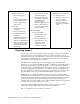
You will need a flat-blade screwdriver and a Phillips-head screwdriver to install your expansion unit. Each type of enclosure comes with general installation instructions for installing optional devices. Before you begin, review the following assumptions: • If you are installing the expansion unit in a rack, you have already installed the other components in the rack and moved the rack to its permanent operating location.
Setting the interface options and ID settings When you install a drive CRU in the expansion unit, the drive tray plugs into a printed circuit board called the midplane. The midplane sets the SCSI bus number and ID automatically. The switch card located on the back of the expansion unit has five external option switches, four internal option switches, and a unit ID switch. It is easier to set these switches before you install the expansion unit in a rack or tower enclosure.
Attention: A loss of data can occur if you change the position of internal option switch 1 or internal option switch 3 after storing data on the drives. Refer to “Conversion of EXP300 to a tower or from a tower” on page 25 if you want to change the configuration of your expansion unit from a rack (internal switch 1 Off) to a tower (internal switch 1 On) or from a tower to a rack orientation. SCSI buses and IDs There are two SCSI buses (bus 1 and bus 2) in the expansion unit.
Important information for IBM ServeRAID: If you are using a ServeRAID software version earlier than the Version 3.50, the View Configuration screens might show SCSI IDs or bay numbers. If the data shown on the View Configuration screen begins with 0, it denotes SCSI IDs. If the data shown on the View Configuration screen begins with 1, it denotes bay numbers.
Attention: Never remove the bridge card while the expansion unit is turned on. Refer to “Turning the expansion unit on and off” on page 3. ESM and power supply bays The following illustration shows the location of the environmental services monitor (ESM) bays (for the hot-swap ESM boards) and the power supply bays where the hotswap power supplies are located.
System-management software, such as IBM Netfinity Manager™, uses the ID when it provides data and alerts for the expansion unit. For more information on option switch settings, see “Setting the interface options and ID settings” on page 10. The following illustration shows the location of the switch card on the expansion unit.
General-system-error LED (amber) When lit, this amber LED indicates that the unit has a fault, such as in a power supply, ESM board, or hard disk drive. Bridge card bay This is the location of the bridge card CRU. Filler panel Expansion units shipped without a full set of drives (14) contain filler panels in the unused drive bays. Before installing new drives, you must remove the filler panels and save them for later use. Each of the 14 bays must always contain either a filler panel or a drive CRU.
AC power connector The power cord for the power supply connects here. Power-supply/Fan CRU The two hot-swap power supplies with built-in fans are located on the back of the expansion unit. Attention: The EXP300 comes with two power-supply/fan units installed. When one power supply fails, the power-supply unit must be replaced to reestablish redundancy. When replacing the failed unit with the new power supply unit, ensure that this operation is performed in less than 10 minutes to prevent any overheating.
Fault LED (amber) When lit, this amber LED indicates an ESM board failure. SCSI reset LED When lit, this green LED indicates a SCSI bus reset. Push pins Each ESM board has an orange push pin to the bottom left of the board. Use the orange push pin and lever to remove and insert the ESM board. Termination-power LED (green) When lit, this green LED indicates that termination power is present.
Attention: If you re-install a drive in the wrong bay, you could lose data. Drive LEDs Each drive bezel has two LEDs, which indicate the status for that particular drive.
3. Determine the bay into which you want to install the drive. 4. Remove the filler panel. a. Insert a finger into the square hole at the top of the filler panel to grip and pull the panel out of the drive bay. b. Save the filler panel for later use. 5. Install the drive CRU: Note: The hard disk drive comes with a tray already attached. Do not attempt to detach the drive Þ4Ýfrom the trayÞ3Ý. a. Release the blue latch Þ1Ýon the drive CRU by pressing on the inside of the bottom of the tray handle Þ2Ý. b.
Replacing hot-swap drives Drive problems include any malfunctions that delay, interrupt, or prevent successful I/O activity between the hosts and the hard disk drives in the expansion unit. This includes transmission problems between the host controllers, the ESM boards, and the drives. This section explains how to replace a failed drive. Attention: Failure to replace the drives in their correct bays might result in loss of data.
4. Check the drive LEDs. a. When a drive is ready for use, the green activity LED and the amber fault LED are off. b. If the amber fault LED is on, remove the drive from the unit and wait 10 seconds; then, reinstall the drive. ServeRAID information In some cases, the ServeRAID controller will automatically reset the drive to the Hot Spare or Rebuild state.
2 3 7 8 901 456 Installing a hot-swap power supply / fan unit Complete the following steps to install a hot-swap power supply: 1. Ensure that the power supply you are installing is turned off. 2. Grasp the handlesÞ2Ýand slide the power supply into the expansion unit. 3. Tighten the power supply thumbscrews Þ1Ý. 4. Connect the power cord to the power supply. 5. Plug the supply power cord into a properly grounded electrical outlet.
Removing a bridge card: Attention: Before removing the EXP300 bridge card, you must turn off the expansion unit. Refer to “Turning the expansion unit on and off” on page 3 for detailed instructions. Complete the following steps to remove the EXP300 bridge card: 1. Turn off the expansion unit. Refer to “Turning the expansion unit on and off” on page 3. 2. Remove the drive CRUs or blank filler panels from the left and right of the bridge card bay. Refer to “Replacing hot-swap drives” on page 20. 3.
There is one switch card located between the two power supply/fan units at the back of the unit. Complete the following steps to remove the switch card: 1. Turn off the expansion unit. 2. Locate the blue push pin Þ2Ý at the bottom of the switch card tray. 3. Pull out the blue push pin Þ2Ý. 4. Pull up on the switch-card tray handle Þ1Ý. 5. Slide the tray that contains the switch card out of the switch card bay.
5. Holding the pin, pull the tray handle Þ3Ý out and to the right. 6. Slide the ESM boardÞ2Ýout of the expansion unit. Installing an ESM board: There are two hot-swap ESM boards at the back of the unit. You can install the ESM board and SCSI cable without turning off power to the EXP300. Complete the following steps to install an EXP300 ESM board: 1. Hold the board so the tray handle Þ3Ý is attached to the bottom of the tray, and the tray handle Þ3Ý is fully extended. 2.
• ID1 - ID13, • ID2 - ID12, • ID3 - ID11, • ID4 - ID10, • ID5 - ID9, • ID6 - ID8. 7. Remove the Netfinity EXP300 from its current rack, Netbay or tower. 8. Place the Netfinity EXP300 into its new home, rack, Netbay or tower. 9. If internal switch 3 on the switch card of your Netfinity EXP300 is set on (split bus or dual bus mode), then ensure that the SCSI cable, if plugged into the left side of the Netfinity EXP300, is now plugged into the right side and vice versa.
Note: Use clip nuts if your rack has round holes. If your rack has square holes, you can use the rack-insertion tool or a flat-blade screwdriver to install cage nuts.
2. On the rail marked R, loosen the four screwsÞ2Ýand adjust the rail. 3. Hold the rail against the outside of the right rack-mounting flange, and loosely insert the two front M6 hex screws Þ1Ý. 4. Extend the rail outside of the rear rack-mounting flange; then, install and tighten two rear M6 hex screws Þ3Ý. 5. Tighten the two front screws Þ1Ý; then, tighten the four screws Þ2Ý. Repeat step 2 through step 5 to install the rail marked L on the left side of the rack. 6.
Statement 4 ≥18 kg (37 lbs) ≥32 kg (70.5 lbs) ≥55 kg (121.2 lbs) CAUTION: Use safe practices when lifting. 7. Slide the expansion unit into the rack, and insert the M6 screws Þ1Ý. Do not overtighten the M6 Þ1Ý screws. 8. Tighten the rear screws Þ2Ý. 9. Verify that option switches 1 and 2 (inside the switch card) are set to off (see “Setting the interface options and ID settings” on page 10 for more information). 10.
• Review the Safety Information that comes with your EXP300 • Refer to “Locations” on page 8 for removing the switch card, environmental services monitor (ESM) boards, fan and power supply assemblies, and hard drives to reduce the weight of your EXP300 Note: The illustrations in this documentation might be slightly different from your hardware. Statement 4 ≥18 kg (37 lbs) ≥32 kg (70.5 lbs) ≥55 kg (121.2 lbs) CAUTION: Use safe practices when lifting. 1.
3. Unlock the door Þ3Ý and hold it at a 90 degree angle to the front of the enclosure; then, lower the top of the door over the tab Þ1Ý on the top of the enclosure. 4. Push the bottom of the door until it snaps into place over the tab Þ2Ý on the bottom of the enclosure. 5. Verify the settings for internal Option Switch 1 and internal Option Switch 2 on the switch card. Internal Option Switch 1 defines hard drive enumeration as either left-to-right (Off) or top-to-bottom (On).
8, 9, 10, 11, 12, 13, and 14; and the seven internal Bus-2 bays to SCSI IDs 0, 1, 2, 3, 4, 5, and 6 Attention: A loss of data can occur if you change the position of internal Option Switch 1 or internal Option Switch 3 after storing data on the hard drives. Refer to “Conversion of EXP300 to a tower or from a tower” on page 25 if you previously stored data on the drives and you now want to change the configuration of your expansion unit from a rack to a tower orientation. a.
a. Verify the setting of the unit ID switch (sometimes referred to as a box ID or a tray ID). b. Locate the expansion unit ID labels that come with this kit; then, apply the label that matches the setting for the unit ID in the blank label area directly below the SCSI ID label. 3. Refer to “Turning the expansion unit on and off” on page 3 for information about turning on the expansion unit.
Front Rear 3. On the rail marked L, loosen the four screws Þ3Ý. 4. Hold the rail against the outside of the left enclosure-mounting flange, and loosely insert the two M6 hex screws Þ4Ý. 5. Extend the rail outside of the rear enclosure mounting flange; then, install and tighten the two rear M6 hex screws Þ5Ý. 6. Tighten the two front hex screws Þ4Ý; then, tighten the four screws Þ3Ý. Repeat step 3 through step 5 to install the rail marked R on the right side of the enclosure. 7.
Completing the installation After you install the hard disk drives and power supplies, follow the instructions in this section to complete the installation. Instructions for installing the identification labels and cabling the expansion unit are included. Installing identification labels Your expansion unit comes with one sheet of 10 labels (0-9) and one sheet of 4 labels (SCSI ID) labels.
2. Install the expansion unit ID label. a. Verify the setting of the expansion unit number switch (0-9). b. Apply the expansion unit ID label that matches the setting for the unit ID switch in the blank label area directly to the left of the SCSI ID label. 3. Continue with “Cabling the expansion unit”. Cabling the expansion unit This section provides the SCSI and power cabling information.
SCSI cable restriction: The SCSI controller inside your server must have a dedicated SCSI channel for the expansion unit. If an external channel is being used for the expansion unit, its corresponding internal channel must not be used for other devices. Power cabling: The expansion unit uses two or four power cords, depending on your country.
Index System (Netfinity EXP300 – Type 3531) FRU No.
Index System (Netfinity EXP300 – Type 3531) FRU No. 18.2 GB 10K rpm Ultra160 SCSI Hard Disk Drive 19K0614 36.
40 IBM Netfinity EXP300 - Type 3531 Hardware Maintenance Manual
Chapter 2. Related service information Note: The service procedures are designed to help you isolate problems. They are written with the assumption that you have model-specific training on all computers, or that are familiar with the computers, functions, terminology, and service information provided in this manual. Safety information The following section contains the safety information that you need to be familiar with before servicing an IBM computer.
• After service, reinstall all safety shields, guards, labels, and ground wires. Replace any safety device that is worn or defective. • Reinstall all covers correctly before returning the machine to the customer. Electrical safety CAUTION: Electrical current from power, telephone, and communication cables can be hazardous.
Observe the special safety precautions when you work with very high voltages; these instructions are in the safety sections of maintenance information. Use extreme care when measuring high voltages. • Regularly inspect and maintain your electrical hand tools for safe operational condition. • Do not use worn or broken tools and testers. • Never assume that power has been disconnected from a circuit. First, check that it has been powered-off.
1. Check exterior covers for damage (loose, broken, or sharp edges). 2. Power-off the computer. Disconnect the power cord. 3. Check the power cord for: a. A third-wire ground connector in good condition. Use a meter to measure third-wire ground continuity for 0.1 ohm or less between the external ground pin and frame ground. b. The power cord should be the appropriate type as specified in the parts listings. c. Insulation must not be frayed or worn. 4. Remove the cover. 5.
— Use the round ground-prong of the ac plug on ac-operated computers. Grounding requirements Electrical grounding of the computer is required for operator safety and correct system function. Proper grounding of the electrical outlet can be verified by a certified electrician.
• Disconnect the attached power cords, telecommunications systems, networks, and modems before you open the device covers, unless instructed otherwise in the installation and configuration procedures. • Connect and disconnect cables as described in the following table when installing, moving, or opening covers on this product or attached devices. To Connect 1. Turn everything OFF. 1. Turn everything OFF. 2. First, attach all cables to devices. 2. First, remove power cords from outlet. 3.
DANGER Some laser products contain an embedded Class 3A or Class 3B laser diode. Note the following: Laser radiation when open. Do not stare into the beam, do not view directly with optical instruments, and avoid direct exposure to the beam. • Statement 4 ≥18 kg (37 lbs) ≥32 kg (70.5 lbs) ≥55 kg (121.2 lbs) CAUTION: Use safe practices when lifting.
Do not place any object weighing more than 82 kg (180 lbs.) on top of rack-mounted devices.
Importante: Todas as instruções de cuidado e perigo da Netfinity Server Library começam com um número. Este número é utilizado para fazer referência cruzada de uma instrução de cuidado ou perigo no idioma inglês com as versões traduzidas das instruções de cuidado ou perigo encontradas nesta seção. Por exemplo, se uma instrução de cuidado é iniciada com o número 1, as traduções para aquela instrução de cuidado aparecem nesta seção sob a instrução 1.
Para Conectar: Para Desconectar: 1. DESLIGUE Tudo. 1. DESLIGUE Tudo. 2. Primeiramente, conecte todos os cabos aos dispositivos. 2. Primeiramente, remova os cabos de alimentação das tomadas. 3. Conecte os cabos de sinal aos conectores. 3. Remova os cabos de sinal dos conectores. 4. Conecte os cabos de alimentação às tomadas. 4. Remova todos os cabos dos dispositivos. 5. LIGUE os dispositivos.
PERIGO Alguns produtos a laser contêm um diodo laser da Classe 3A ou Classe 3B embutido. Observe o seguinte: Radiação de laser quando aberto. Não olhe diretamente para o raio a olho nu ou com instrumentos íticos, e evite exposição direta ao raio. Instrução 4 ≥18 kg (37 lbs) ≥32 kg (70,5 lbs) ≥55 kg (121,2 lbs) CUIDADO: Ao levantar a máquina, faça-o com segurança.
Não coloque nenhum objeto com peso superior a 82 kg (180 lbs.) sobre dispositivos montados em rack.
Chapter 2.
54 IBM Netfinity EXP300 - Type 3531 Hardware Maintenance Manual
Chapter 2.
56 IBM Netfinity EXP300 - Type 3531 Hardware Maintenance Manual
Chapter 2.
58 IBM Netfinity EXP300 - Type 3531 Hardware Maintenance Manual
Chapter 2.
60 IBM Netfinity EXP300 - Type 3531 Hardware Maintenance Manual
Important: Toutes les consignes Attention et Danger indiquées dans la bibliothèque Netfinity Server sont précédées d'un numéro. Ce dernier permet de mettre en correspondance la consigne en anglais avec ses versions traduites dans la présente section. Par exemple, si une consigne de type Attention est précédée du chiffre 1, ses traductions sont également précédées du chiffre 1 dans la présente section.
Connexion Déconnexion 1. Mettez les unités hors tension. 1. Mettez les unités hors tension. 2. Commencez par brancher tous les cordons sur les unités. 2. Débranchez les cordons d'alimentation des prises. 3. Branchez les câbles d'interface sur des connecteurs. 3. Débranchez les câbles d'interface des connecteurs. 4. Branchez les cordons d'alimentation sur des prises. 4. Débranchez tous les câbles des unités. 5. Mettez les unités sous tension.
DANGER Certains produits laser contiennent une diode laser de classe 3A ou 3B. Prenez connaissance des informations suivantes: Rayonnement laser lorsque le carter est ouvert. évitez de regarder fixement le faisceau ou de l'observer à l'aide d'instruments optiques. évitez une exposition directe au rayon. Notice n° 4 ≥18 kg ≥32 kg ≥55 kg ATTENTION: Faites-vous aider pour soulever ce produit.
ATTENTION: Ne posez pas d'objet dont le poids dépasse 82 kg sur les unités montées en armoire.
Wichtig: Alle Sicherheitshinweise in dieser Netfinity Server-Bibliothek beginnen mit einer Nummer. Diese Nummer verweist auf einen englischen Sicherheitshinweis mit den übersetzten Versionen dieses Hinweises in diesem Abschnitt. Wenn z. B. ein Sicherheitshinweis mit der Nummer 1 beginnt, so erscheint die übersetzung für diesen Sicherheitshinweis in diesem Abschnitt unter dem Hinweis 1. Lesen Sie alle Sicherheitshinweise, bevor Sie eine Anweisung ausführen.
Kabel anschlieβen: 1. Alle Geräte ausschalten und Netzstecker ziehen. 2. Zuerst alle Kabel an Einheiten anschließen. 3. Signalkabel an Anschlußbuchse n anschließen. Kabel lösen: 1. Alle Geräte ausschalten. 2. Zuerst Netzstecker von Steckdose lösen. 3. Signalkabel von Anschlußbuchsen lösen. 4. Alle Kabel von Einheiten lösen. 4. Netzstecker an Steckdose anschließen. 5. Gerät einschalten.
• Steuer- und Einstellelemente sowie Verfahren nur entsprechend den Anweisungen im vorliegenden Handbuch einsetzen. Andernfalls kann gefährliche Laserstrahlung auftreten. VORSICHT Manche CD-ROM-Laufwerke enthalten eine eingebaute Laserdiode der Klasse 3A oder 3B. Die nachfolgend aufgeführten Punkte beachten. Laserstrahlung bei geöffneter Tür. Niemals direkt in den Laserstrahl sehen, nicht direkt mit optischen Instrumenten betrachten und den Strahlungsbereich meiden.
ACHTUNG: Keine Gegenstände, die mehr als 82 kg wiegen, auf Rack-Einheiten ablegen.
Importante: Tutti gli avvisi di attenzione e di pericolo riportati nella pubblicazione Netfinity Server Library iniziano con un numero. Questo numero viene utilizzato per confrontare avvisi di attenzione o di pericolo in inglese con le versioni tradotte riportate in questa sezione. Ad esempio, se un avviso di attenzione inizia con il numero 1, la relativa versione tradotta è presente in questa sezione con la stessa numerazione.
Per collegare: Per scollegare: 1. SPEGNERE tutti i dispositivi. 1. SPEGNERE tutti i dispositivi. 2. Collegare prima tutti i cavi alle unità. 2. Rimuovere prima i cavi di alimentazione dalle prese elettriche. 3. Collegare i cavi di segnale ai connettori. 4. Collegare i cavi di alimentazione alle prese elettriche. 3. Rimuovere i cavi di segnale dai connettori. 4. Rimuovere tutti i cavi dalle unità. 5. ACCENDERE le unità.
PERICOLO Alcuni prodotti laser contengono all’interno un diodo laser di Classe 3A o Classe 3B. Prestare attenzione a quanto segue: Aprendo l'unità vengono emesse radiazioni laser. Non fissare il fascio, non guardarlo direttamente con strumenti ottici ed evitare l'esposizione diretta al fascio. Avviso 4 ≥18 kg ≥32 kg ≥55 kg ATTENZIONE: Durante il sollevamento della macchina seguire delle norme di sicurezza.
ATTENZIONE: Non poggiare oggetti che pesano più di 82 kg sulla parte superiore delle unità montate in rack.
Chapter 2.
74 IBM Netfinity EXP300 - Type 3531 Hardware Maintenance Manual
Chapter 2.
Importante: Todas las declaraciones de precauciín de esta Biblioteca del servidor Netfinity empiezan con un número. Dicho número se emplea para establecer una referencia cruzada de una declaraciín de precauciín o peligro en inglés con las versiones traducidas que de dichas declaraciones pueden encontrarse en esta secciín. Por ejemplo, si una declaraciín de peligro empieza con el número 1, las traducciones de esta declaraciín de precauciín aparecen en esta secciín bajo Declaraciín 1.
Para la conexin 1. APÁGUELO todo. 2. En primer lugar, conecte los cables a los dispositivos. 3. Conecte los cables de señal a los conectores. 4. Conecte cada cable de alimentaciín a la toma de alimentaciín. Para la desconexiín 1. APÁGUELO todo. 2. En primer lugar, retire cada cable de alimentaciín de la toma de alimentaciín. 3. Retire los cables de señal de los conectores. 4. Retire los cables de los dispositivos. 5. ENCIENDA el dispositivo.
• El uso de controles o ajustes o la realizaciín de procedimientos que no sean los que se han especificado aquí pueden dar como resultado una exposiciín perjudicial a las radiaciones. PELIGRO Algunos productos láser contienen un diodo de láser incorporado de Clase 3A o de Clase 3B. Tenga en cuenta la advertencia siguiente. Cuando se abre, hay radiaciín láser. No mire fijamente el rayo ni lleve a cabo ningún examen directamente con instrumentos ípticos; evite la exposiciín directa al rayo.
PRECAUCIÓN: No coloque ningún objeto que pese más de 82 kg (180 libras) encima de los dispositivos montados en bastidor. Chapter 2.
Send us your comments! We want to know your opinion about this manual (part number 06P8514). Your input will help us to improve our publications. Please photocopy this survey, complete it, and then fax it to IBM HMM Survey at 919-543-8167 (USA). Name: _________________________________________ Phone number: __________________________________ 1. Do you like this manual? ❑ Yes ❑ No _________________________________________ _________________________________________ 2.
• Machine type and model • Processor or hard disk upgrades • Failure symptom — Do diagnostics fail? — What, when, where, single, or multiple systems? — Is the failure repeatable? — Has this configuration ever worked? — If it has been working, what changes were made prior to it failing? — Is this the original reported failure? • Reference/Diagnostics version — Type and version level • Hardware configuration — Print (print screen) configuration currently in use — BIOS level • Operating system softw
IBM Netfintiy Director NetBAY Netfinity Netfinity Manager ThinkPad SystemXtra ServeRAID The following terms are trademarks of other companies: Notes Lotus Development Corporation MMX and Pentium are trademarks or registered trademarks of Intel Corporation. UNIX is a trademark or registered trademark of The Open Group in the United States and other countries. Windows NT is a trademark or registered trademark of Microsoft Corporation.
IBM Part Number: 06P8514 06P8514 Printed in the United States of America on recycled paper containing 10& recovered post-consumer fiber.
IBM