iSeries 270 and 820 30xx Memory Card Installation Version 5 SENG-3002-01
iSeries 270 and 820 30xx Memory Card Installation Version 5 SENG-3002-01
Note Before using this information and the product it supports, be sure to read the “Safety and Environmental Notices” on page iii and the “Notices” on page 19. Second Edition (May 2001) This edition applies only to reduced instructions set computer (RISC) systems. © Copyright International Business Machines Corporation 2000, 2001. All rights reserved. US Government Users Restricted Rights – Use, duplication or disclosure restricted by GSA ADP Schedule Contract with IBM Corp.
Safety and Environmental Notices Danger Notices A danger notice calls attention to a situation that is potentially lethal or extremely hazardous to people. DANGER To prevent a possible electrical shock during an electrical storm, do not connect or disconnect cables or station protectors for communications lines, display stations, printers, or telephones.
Product Recycling and Disposal Components of the system, such as structural parts and circuit cards, can be recycled where recycling facilities exist. IBM does not currently collect and recycle used IBM products from customers in the United States other than those products that are involved in trade-in programs. Companies are available to disassemble, reutilize, recycle, or dispose of electronic products. Contact an IBM account representative for more information.
Installation Instructions Before you begin __ 1. Take a minute to become familiar with these instructions. Note that you may not complete every step in this instruction. __ 2. These instructions contain steps on how to install memory (main storage cards), including adding another 2884 card assembly, into the system unit. __ 3. This feature is customer installed. The installation of this feature is intended for an experienced user who understands industry terminology and who has some system experience.
__ 9. If you encounter difficulties during the installation, contact your authorized dealer or service provider. Powering off the system unit __ 1. Set the System performance adjustment to a value other than option 0. __ a. On an iSeries command line, type WRKSYSVAL (QPFRADJ) and press Enter. __ b. Select the Change option on the Work with System Values display and press Enter. __ c. If you have a Performance adjustment value of option 1, option 2, or option 3 you do not need to change the value.
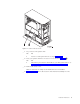
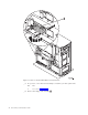
Figure 1. Location of Access Cover __ 1. Do you have a 270 system unit? Yes No ↓ You have a 820 system unit. Go to step 5 on page 4. __ 2. Does your system unit have an access cover as shown in Figure 1 A ? Yes No ↓ The memory is located on the inside of your 270 system unit. Go to “Installing memory cards inside your system unit” on page 7. __ 3. Remove the access cover. Note: A customer can safely use all latches that are colored blue. __ 4.
Figure 2. Location of card assembly 2884 in a 270 system unit __ 5. Do you have a new 2884 card assembly to install in your 820 system unit? Yes No ↓ Go to step 7 on page 5. __ 6. Remove the empty card assembly C .
Figure 3. Location of Card Assembly 2884 in 820 Unit __ 7. Remove the 2884 card assembly B or C from the system unit by doing the following: __ a. Unlatch the two blue latches on the 2884 until the card assembly slightly “pops” out. __ b. Pull on both latches at the same time to remove the card assembly from the system unit. __ c. Turn the card assembly over and lay it on the static protective bag provided. Adding memory to the card assembly __ 1.
Figure 4. Memory Locations on Card Assembly __ 2. Remove the blank filler cards from the next available positions by doing the following: __ a. Push outward on the latches A that are located at each end of the filler card, Figure 5 on page 7. __ b. Remove the filler card from the card socket and discard it. __ 3. Find the package that contains the new memory cards. __ 4. Attention: Memory cards are fragile. Handle with care. Remove a memory card, one at a time, from the static protective package. __ 5.
Figure 5. Install Memory Cards __ 6. Install the remaining memory cards. __ 7. When you finish installing all the memory cards, turn the card assembly over, and slide it into the system unit. Push on both card latches at the same time. Close the latches when you cannot push the card assembly any further into the system unit. __ 8. Reinstall the access cover. __ 9. You have completed the installation of the memory cards in your system. Go to “Installing system unit covers” on page 10.
Figure 6.
Figure 7. Memory Connectors View 2 __ 2. Refer to the figure that matches your system unit to place the memory in the correct order. __ 3. Place memory cards as follows on the processor: v In pairs, beginning with C and D, then E and F, and so on. v Each pair of storage cards must be either 128MB, 256MB, or 512MB. __ 4. Remove the blank filler cards from the next available positions by doing the following: __ a.
__ 8. Install the second memory card. __ 9. Do you have any other adapter cards or devices to install? No Yes ↓ If you have another device such as an adapter card, a tape unit, or disk units to install, go to the instructions that came with that device. Go to “Installing system unit covers”. Installing system unit covers __ 1. Remove the wrist strap. __ 2. Figure 8 shows how to install the system unit side cover by aligning the tabs on the top and bottom edge.
__ 4. DANGER An electrical outlet that is not correctly wired could place hazardous voltage on metal parts of the system or the products that attach to the system. It is the customer’s responsibility to ensure that the outlet is correctly wired and grounded to prevent an electrical shock. (RSFTD201) Plug the following power cords into an electrical outlet. v System unit Note: Do not power on your system unit at this time. v System unit console __ 5.
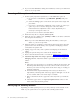
__ a. Press the Mode Select button until the Manual mode indicator (a small hand) lights up. __ b. Press the Increment/Decrement push button until 02 appears in the Function/Data display. __ c. Press the Enter push button on the control panel. __ d. Press the Increment/Decrement push button until B appears in the Function/Data display. __ e. Press the Enter push button on the control panel. __ f. Press the Increment/Decrement push button until S appears in the Function/Data display. __ g.
Note: If the status is not Operational, check the memory cards. __ g. If you have a printer, print the configuration list. Note: To print the hardware resources list, press F12 one time. When the Logical Hardware Resources menu appears, press F6. __ h. To return to the Main Menu, press F3 three times and then press Enter. __ 10. If you changed the System performance adjustment option value in step 1 on page 2, do the following to return to what you had prior to your upgrade: __ a.
14 30xx Memory Card Installation V5R1
Unit Covers Locate the diagram of the unit you are working on. If you have a 270 system unit in a rack, go to “270 unit in a rack” on page 16. 270 and 820 System Units To access the PCI card location, you need to remove the back cover and the side cover: __ 1. Place your hand near the bottom of the back cover and lift up and out. __ 2. Attention: If removing side cover while powered on, errors may occur due to electromagnetic interference.
270 unit in a rack 1. Press latches B and pull the server out using the handle C . 2. Refer to previous unit diagram to remove the side cover.
System unit control panel Go to the front of your system unit. Open the control panel door. Your control panel looks like either Figure 9 or Figure 10 on page 18. Refer to the control panel for your unit. Figure 9. Control panel without Electronic Keystick A Power On Light v A blinking light indicates power to the unit. v A constant light indicates that the unit is up and working.
If your control panel looks like this, before you can use F Increment/Decrement buttons and G Enter push button, you need to press H Mode Selects to select Manual mode N . Figure 10. Control panel with Electronic Keystick 18 A Power On Light v A blinking light indicates power to the unit. v A constant light indicates that the unit is up and working.
Notices This information was developed for products and services offered in the U.S.A. IBM may not offer the products, services, or features discussed in this document in other countries. Consult your local IBM representative for information on the products and services currently available in your area. Any reference to an IBM product, program, or service is not intended to state or imply that only that IBM product, program, or service may be used.
Trademarks The following terms are trademarks of the IBM Corporation in the United States or other countries or both: AS/400 AS/400e series Client Access Client Access/400 IBM NetFinity Operating System/400 OS/400 400 800-IBM-CALL Microsoft, Windows, Windows NT, and the Windows 95 logo are trademarks or registered trademarks of Microsoft Corporation. Other company, product, and service names, which may be denoted by a double asterisk (**), may be trademarks or service marks of others.
Readers’ Comments — We’d Like to Hear from You iSeries 270 and 820 30xx Memory Card Installation Version 5 Publication No.
SENG-3002-01 ___________________________________________________________________________________________________ Readers’ Comments — We’d Like to Hear from You Cut or Fold Along Line _ _ _ _ _ _ _Fold _ _ _and _ _ _Tape _ _ _ _ _ _ _ _ _ _ _ _ _ _ _ _ _ _ _ _ _ _ _ _ _ _ _Please _ _ _ _ _do _ _not _ _ staple _ _ _ _ _ _ _ _ _ _ _ _ _ _ _ _ _ _ _ _ _ _ _ _ _ _ _ _ _Fold _ _ _and _ _ Tape ______ NO POSTAGE NECESSARY IF MAILED IN THE UNITED STATES BUSINESS REPLY MAIL FIRST-CLASS MAIL PERMIT NO.
Printed in the United States of America on recycled paper containing 10% recovered post-consumer fiber.