IBM NetVista Hardware Maintenance Manual A40 Type 6830/6831 A40i Type 2251
IBM NetVista Hardware Maintenance Manual A40 Type 6830/6831 A40i Type 2251
Note: Before using this information and the product it supports, be sure to read the general information under “Notices” on page 141.
About this manual This manual contains service and reference information for the IBM« NetVistaTM Series computer type 2251/6830/6831. This manual is divided into product service sections (by machine chassis) and a related service section, as follows: v The product service sections include procedures for isolating problems to a FRU, a Symptom-to-FRU Index, additional service information and an illustrated parts catalog.
Leia todas as instruções de cuidado e perigo antes de executar qualquer operação. Lea atentamente todas las declaraciones de precaución y peligro ante de llevar a cabo cualquier operación.
Contents About this manual . . . . . . . . . . iii Important Safety Information . . . . . . . . iii Chapter 1. General Checkout. . . . . . 1 Chapter 2. General Information . . . . . 3 Features . . . Specifications . . . . . . . . . . . . . . . . . . . . . . . . . . 3 . 5 Chapter 3. Diagnostics . . . . . . . . 7 Setup Utility program . . . . . . . . . . . 8 Product Recovery Program menu . . . . . . . 9 Diagnostics . . . . . . . . . . . . . . 10 Diagnostics download . . . . . . . . . .
Chapter 9. Related Service Information . . . . . . . . . . . . 103 Safety notices (multi-lingual translations) . Safety Information. . . . . . . . . General Safety . . . . . . . . . Grounding requirements . . . . . Electrical safety. . . . . . . . . Handling electrostatic discharge-sensitive devices . . . . . . . . . . . Safety inspection guide . . . . . . Problem determination tips. . . . . . File updates . . . . . . . . . . vi Hardware Maintenance Manual . . . . . . . . . . . . . . .
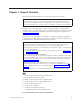
Chapter 1. General Checkout This general checkout procedure is for type 2251/6830/6831 computers. Attention: The drives in the computer you are servicing might have been rearranged or the drive startup sequence changed. Be extremely careful during write operations such as copying, saving or formatting. Data or programs can be overwritten if you select an incorrect drive. Diagnostic error messages appear when a test program finds a problem with a hardware option.
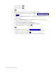
If NO, continue to 002 . If YES, proceed to 003 . 002 If the Power Management feature is enabled, do the following: 1. Start the Configuration/Setup Utility program (see “Setup Utility program” on page 8) 2. Select Power Management from the Configuration/Setup Utility program menu. 3. Select APM. 4. Be sure APM BIOS Mode is set to Disabled. If it is not, press Left Arrow (}) or Right Arrow (Æ) to change the setting. 5. Select Automatic Hardware Power Management. 6.
Chapter 2. General Information Features The NetVista type 2251/6830/6831 computers are available in 4 x 4 (three I/O adapter slots, plus one AGP slot, and four drive bays). Not all models come with all features summarized here. Microprocessor Intel« Pentium¬ III microprocessor with 256 KB of internal L2 cache memory Memory v Support for dual inline memory modules (DIMMs) – 3.
v v v v v Standard mouse port Standard keyboard port 15-pin monitor port Three audio connectors (line/headphone out, line in, and microphone) Joystick/MIDI connectors (some models) Expansion v Drive bays: 4 v PCI expansion slots: 3 v One AGP expansion slot Power v 155 W power supply with manual voltage selection switch v Automatic 50/60 Hz input frequency switching v Advanced Power Management support v Advance Configuration and Power Interface (ACPI) support Security features v Power-on and administrator
Specifications Dimensions Height: 425 mm (16.7 in.) Width: 140 mm (5.5 in.) Depth: 425 mm (16.7 in.) Weight Minimum configuration as shipped: 9.4 kg (20 lb) Maximum configuration: 11.3 kg (25.0 lb) Environment Air temperature: System on: 10° to 35°C (50° to 95° F) System off: 10° to 43° C (50° to 110° F) Maximum altitude: 2134 m (7000 ft) Note: The maximum altitude, 2134 m (7000 ft), is the maximum altitude at which the specified air temperatures apply.
6 Hardware Maintenance Manual
Chapter 3. Diagnostics Setup Utility program . . . . . . . . . . . 8 Product Recovery Program menu . . . . . . . 9 Diagnostics . . . . . . . . . . . . . . 10 Diagnostics download . . . . . . . . . . 10 Navigating through the diagnostic programs . . 10 Running diagnostic tests . . . . . . . . . 10 Test selection . . . . . . . . . . . . . 10 Module test menu/hardware configuration report 11 Memory Diagnostic tests . . . . . . . . . 11 Alert-On LAN¬ test. . . . . . . . . . . 12 Asset ID¬ test . . . . . . . .
Setup Utility program Attention: A customized setup configuration (other than default settings) might exist on the computer you are servicing. Running the Setup Utility program might alter those settings. Note the current configuration settings and verify that the settings are in place when service is complete. The Setup Utility (configuration) program is stored in the permanent memory of the computer.
Product Recovery Program menu Type 2251/6830/6831 machines have recovery and diagnostics programs on a separate hard drive partition. The Diagnostics diskette is not shipped with the machine or the HMM. To download the diagnostics program, see “Diagnostics download” on page 10.
Diagnostics The diagnostic programs use a full range of diagnostic utilities to determine the operating condition of the computer’s hardware components. For a complete list of error codes and messages, see ″Symptom-to-FRU Index″ on page 39. Diagnostics download To download the diagnostic programs, do the following: v Go to http://www.ibm.com/. v Select Support. v Select Desktop computing from the ″Search by Category″ pull-down menu. v Select NetVista from the ″Product Family″ list.
A selected test is marked by >>. Pressing the space bar again de-selects a test and removes the chevron. 4. Repeat steps 2 and 3 above to select all desired tests. Module test menu/hardware configuration report Depending on the diagnostic version level you are using, the installed devices in the computer are verified in one of two ways. 1. At the start of the diagnostic tests, the Module Test Menu is displayed. Normally, all installed devices in the computer are highlighted on the menu. 2.
v Memory Test-Quick The quick memory test will take about 20 seconds per MB of memory and will detect solid (stuck) memory failures only. Notes: Either level of memory testing can be performed on all memory or a single SIMM or DIMM socket. Only sockets containing a SIMM or DIMM can be selected for testing. Unpopulated sockets are noted by ........ beside the test description. Alert-On LAN¬ test The Alert On LAN test does the following: v Determines if Alert On LAN is supported on the system.
v ChkDigits: Contains a 2-digit check-digit value to ensure the following: – Diagnostics were run on the specified date. – Diagnostics were run on the specified IBM computer. – The diagnostic error code is recorded correctly. v Text: Description of the error. Note: See “Diagnostic error codes” on page 42 for error code listings. Hard file Smart test Use the Hard File Smart Test when the system management tool has detected a hard file SMART alert.
v Destroys all copies of the FAT Table on all partitions (both the master and backup). v Destroys the partition table. v Provides messages that warn the user that this is a non-recoverable process. The Full Erase Hard Drive provides a DOS utility that performs the following steps. v Performs all the steps in Quick Erase. v Provides a DOS utility that writes random data to all sectors of the hard drive. v Provide an estimate of time to completion along with a visual representation of completion status.
When to use the Low-Level Format program Notes: 1. The low-level format is not available on all diagnostic diskettes. 2. Before formatting the hard disk drive, make a backup copy of the files on the drive to be formatted. Use the Low-Level Format program in the following situations: v When you are installing software that requires a low-level format. v When you get recurring messages from the test programs directing you to run the Low-Level Format program on the hard disk.
16 Hardware Maintenance Manual
Chapter 4. Installing Options Input/Output connectors . . . Removing the cover . . . . Installing adapters . . . . . AGP adapter . . . . . . Audio adapter . . . . . ADSL modem . . . . . Home PNA network adapter © Copyright IBM Corp. 2000 . . . . . . . . . . . . . . . . . . . . . . . . . . . . . . . . . . . . . . . . . . . . . . . . . 18 19 20 20 21 21 21 Installing internal drives . . . . . Installing drives in bays 1, 2 and 3 CD-ROM drive jumper settings. Installing a hard drive in bay 4 . .
Input/Output connectors 2 1 1 2 1 2 3 4 5 6 7 18 Mouse connector Keyboard connector USB connector 2 USB connector 1 Serial connector 1 Parallel connector Monitor connector Hardware Maintenance Manual 8 Microphone connector 9 Audio in connector 10 Audio out connector 11 Serial connector 2 12 SVGA Monitor connector 13 DVI Monitor connector
Removing the cover To remove the cover, do the following: 1. Remove the thumbscrews from the rear of the computer and slide the cover toward the rear of the computer. Chapter 4.
Installing adapters To install an adapter, do the following: 1. Remove the cover (see “Removing the cover” on page 19). 2. Remove the slot cover for the appropriate expansion slot. 3. Remove the adapter from its static-protective package. 4. Install the adapter into the appropriate slot on the system board. 5. Install the screw that secures the adapter.
1 Connector Digital video interface (DVI) connector 2 S-Video connector 3 SVGA monitor converter 4 SVGA monitor converter Description Used to attach a digital monitor. This connector provides the signals necessary to support the Display Power Management Signaling (DPMS) standard. Used to attach a television set that has a S-Video connector. The S-Video cable (required to connect the television set to the adapter) is a separately purchased item.
Installing internal drives 1 Bay 1 - Max Height: 2 Bay 2 - Max Height: 3 Bay 3 - Max Height: 4 Bay 4 - Max Height: 41.3 mm (1.6 in.) CD-ROM drive (standard in some models) 5.25-inch hard disk drive 41.3 mm (1.6 in.) 5.25-inch hard disk drive 3.5-inch hard disk drive (requires a mounting bracket) CD-ROM drive DVD-ROM drive 25.4 mm (1.0 in.) 3.5-inch diskette drive (preinstalled) 25.4 mm (1.0 in.
gently pry the static shield loose from the drive bay. 3. Install the drive into the bay. Align the screw holes and insert the two screws. 4. Connect the power and signal cables to the drive. CD-ROM drive jumper settings CD-ROM and PC/CD-ROM drives use jumpers or tabs to set the drives as primary (master) or secondary (slave). Refer to the drive connector labels or the figures Chapter 4.
below for the drive settings. AUDIO RGGL IDE INTERFACE DC INPUT 39 40 1 2 5V G G 12V See Jumper Settings Below CD-ROM Primary (Master) Secondary (Slave) 40X : : : : 48X : : : : Installing a hard drive in bay 4 To install a hard drive in bay 4, do the following: 1. Remove the cover (see “Removing the cover” on page 19). 2. From the bottom of the machine, remove the two screws that retain the hard drive mounting bracket.
3. Slide the bracket up and remove it from the machine. Hard disk drive jumper settings IDE hard disk drives for the NetVista series computers use jumpers to set the drives as primary (master) or secondary (slave). Note: For drives not shown below, refer to the label on the hard disk drive for the hard disk drive settings. 1 Primary (Master) Hard Disk Drive 2 Secondary (Slave) Hard Disk Drive Chapter 4.
26 Hardware Maintenance Manual
Installing a security U-bolt To help prevent hardware theft, you can add a security U-bolt and cable to your computer. After you add the security cable, make sure that it does not interfere with other cables that are connected to the computer. To 1. 2. 3. install a U-bolt: Remove the cover (see “Removing the cover” on page 19). Use a tool, such as a screwdriver, to remove the two metal knockouts.
Replacing the cover To replace the cover, do the following: 1. Ensure that all components have been reassembled correctly and that no tools or loose screws are left inside your computer. 2. Clear any cables that might impede the replacement of the cover. 3. Position the cover over the chassis so that the front edge is approximately one inch away from the front bezel. 4. Lower the cover down over the chassis so that the rail guides engage the rails. 5. Slide the cover forward.
Chapter 5. FRU Replacements Computer exploded view. . . . . . . . A40/A40P/A40i system board layout . . . System board locations . . . . . . . System board jumper settings . . . . . Clear CMOS/Flash Boot Block Recovery. Processor Speed Settings . . . . . . System board memory. . . . . . . . Installing memory . . . . . . . . © Copyright IBM Corp. 2000 . . . . . . . . . . . . . . . . 30 31 31 32 32 32 32 32 Replacing a system board . Replacing a processor . . . Replacing the speaker . . .
Computer exploded view 30 Hardware Maintenance Manual
A40/A40P/A40i system board layout 32 31 System board locations 1 CPU fan connector 2 Microprocessor 3 DIMM 0 4 DIMM 1 5 Power LED connector 6 RFID connector 7 Front USB connector 8 Secondary IDE connector 9 Diskette connector 10 Primary IDE connector 11 Power connector 12 CMOS clear/recovery jumper 13 Fan connector 14 Battery 15 SCSI adapter LED connector 16 Alert on LAN 17 Wake on LAN 18 PCI slot 3 19 PCI slot 2 20 PCI slot 1 21 AGP slot 22 CD-ROM audio 23 Speaker connector
System board jumper settings The following table contains the jumper setting information. (D) indicates the default setting. Clear CMOS/Flash Boot Block Recovery Use the recovery jumper setting to Clear CMOS or to Flash Boot Block Recover. Jumper Setting Description CMOS Reset 2-3 CMOS Reset/Flash Recovery Mode 1-2 (D) Normal Mode Note: The A40/A40P/A40i CMOS clear/recovery jumper pins are numbered as follows: v Pin 1 is the farthest from the battery.
To install a memory module, do the following: 1. Locate the DIMM connectors. 2. If the retaining clips are not already open, open them. 3. Install the DIMM straight down into the connector until the retaining clips close. Make sure the notches in the DIMM align with the tabs on the connector. Notches Chapter 5.
Replacing a system board Important: Before replacing a system board, back up Asset information by using the “Asset EEPROM backup” on page 14. Notes: 1. The BIOS and Vital Product Data (VPD) for the computer you are servicing must be installed on the new system board (FRU) after it is installed in the computer. To do this, you must run the Flash Update program using the Flash Update diskette. See “BIOS levels” on page 97, “Vital product data” on page 95, and “Flash (BIOS/VPD) update procedure” on page 98.
v Memory modules 6. Ensure that the new system board jumper settings match the old system board jumper settings. Replacing a processor Make sure the processor is fully seated in its socket and that the goal post latches are engaged. Important: 1. 2. Make sure the air baffle is installed to prevent processor overheating. If the processor is not installed correctly, the system board and the processor can be damaged. Replacing the speaker To replace the speaker, do the following: 1.
20-pin main power supply connection See “A40/A40P/A40i system board layout” on page 31 for connector locations. Attention: These voltages must be checked with the power supply cables connected to the system board Pin Signal Function 1 3.3 V +3.3 V dc 2 3.3 V +3.3 V dc 3 COM Ground 4 5V +5 V dc 5 COM Ground 6 5V +5 V dc 7 COM Ground 8 POK Power Good 9 5VSB Standby Voltage 10 12 V +12 V dc 11 3.3 V +3.
4. Slide the power supply unit up toward the top of the chassis. 5. Rotate the power supply outward as shown. Chapter 5.
6. Pull the power supply forward and carefully rotate it toward the front of the chassis.
Chapter 6. Symptom-to-FRU Index SIMM/DIMM/RIMM memory Hard disk drive boot error . Diagnostic error codes . . . Beep symptoms . . . . . errors. . . . . . . . . . . . . . . . . . . . . . . . . . . . . . 40 41 42 60 No-beep symptoms . . . . POST error codes . . . . Miscellaneous error messages Undetermined problems . . . . . . . . . . . . . . . . . . . . . . . . . . . . . . . . . . 62 63 77 79 The Symptom-to-FRU index lists error symptoms and possible causes.
SIMM/DIMM/RIMM memory errors The following SIMM/DIMM/RIMM error messages are issued by the diagnostic programs. Error FRU/Action 2xx-1y Replace the SIMM in the socket identified by the last digit of the error code. A memory error was detected in SIMM socket Y. Re-run the test. If the same error code occurs again, replace the system board. 2xx-2y A memory error was detected in DIMM/RIMM socket Y Replace the DIMM/RIMM in the socket identified by the last digit of the error code. Re-run the test.
Hard disk drive boot error A hard disk drive boot error (error codes 1962 and I999030X) can have the following causes. Error FRU/Action The start-up drive is not in the boot sequence in configuration. Check the configuration and ensure the start-up drive is in the boot sequence. No operating system installed on the boot drive. Install an operating system on the boot drive. The boot sector on the start-up drive is corrupted. The drive must be formatted, do the following: 1.
Diagnostic error codes Refer to the following diagnostic error codes when using the diagnostic tests. See ″Diagnostics″ on page 7 for the specific type for information about the diagnostic programs. In the following index, X can represent any number. Diagnostic Error Code FRU/Action 000-000-XXX BIOS Test Passed 1. No action 000-002-XXX BIOS Timeout 1. Flash the system 000-024-XXX BIOS Addressing test failure 1. Flash the system 000-025-XXX BIOS Checksum Value error 1. Flash the system 2.
Diagnostic Error Code FRU/Action 000-197-XXX BIOS test warning 1. Make sure the component that is called out is connected and/or enabled 2. Re-run test 3. Component that is called out in warning statement 4. Component under test 000-198-XXX BIOS test aborted 1. If a component is called out, make sure it is connected and/or enabled 2. Flash the system and re-test 3. Go to the ″Undetermined problems″ section 000-199-XXX BIOS test failed, cause unknown 1. Go to the ″Undetermined problems″ section 2.
Diagnostic Error Code FRU/Action 001-038-XXX System Extension failure 1. Adapter card 001-039-XXX System DMI data structure error 1. Flash the system 001-040-XXX System IRQ failure 1. Power-off/on system and re-test 001-041-XXX System DMA failure 1. Power-off/on system and re-test 001-195-XXX System Test aborted by user 1. Information 001-196-XXX System test halt, error threshold exceeded 1. Press F3 to review the log file 001-197-XXX System test warning 1.
Diagnostic Error Code FRU/Action 001-271-XXX System IRQ4 failure 1. Device on IRQ4 001-272-XXX System IRQ5 failure 1. Device on IRQ5 001-273-XXX System IRQ6 (diskette drive) failure 1. Diskette Cable 001-274-XXX System IRQ7 failure 1. Device on IRQ7 001-275-XXX System IRQ8 failure 1. Device on IRQ8 001-276-XXX System IRQ9 failure 1. Device on IRQ9 001-277-XXX System IRQ10 failure 1. Device on IRQ10 001-278-XXX System IRQ11 failure 1. Device on IRQ11 001-279-XXX System IRQ12 failure 1.
Diagnostic Error Code FRU/Action 001-301-XXX System RTC Century byte error 1. Flash the system 005-000-XXX Video Test Passed 1. No action 005-00X-XXX Video error 1. Video card, if installed 005-010-XXX 005-011-XXX 005-012-XXX 005-013-XXX Video Signal failure 1. Video card, if installed 005-016-XXX Video Simple Pattern test failure 1. Video Ram 005-024-XXX Video Addressing test failure 1. Video card, if installed 005-025-XXX Video Checksum Value error 1.
Diagnostic Error Code FRU/Action 005-197-XXX Video test warning 1. Make sure the component that is called out is connected and/or enabled 2. Re-run test 3. Component that is called out in warning statement 4. Component under test 005-198-XXX Video test aborted 1. If a component is called out, make sure it is connected and/or enabled 2. Flash the system and re-test 3. Go to the ″Undetermined problems″ section 005-199-XXX Video test failed, cause unknown 1. Go to the ″Undetermined problems″ section 2.
Diagnostic Error Code FRU/Action 011-000-XXX Serial port Interface Test Passed 1. No action 011-001-XXX Serial port Presence 1. Remove external serial device, if present 2. Run setup, enable port 3. System board 011-002-XXX 011-003-XXX Serial port Timeout/Parity error 1. System board 011-013-XXX 011-014-XXX Serial port Control Signal/Loopback test failure 1. System board 011-015-XXX Serial port External Loopback failure 1. Wrap plug 011-027-XXX Serial port Configuration/Setup error 1.
Diagnostic Error Code FRU/Action 014-001-XXX Parallel port Presence 1. Remove external parallel device, if present 2. Run setup, enable port 3. System board 014-002-XXX 014-003-XXX Parallel port Timeout/Parity error 1. System board 014-013-XXX 014-014-XXX Parallel port Control Signal/Loopback test failure 1. System board 014-015-XXX Parallel port External Loopback failure 1. Wrap plug 014-027-XXX Parallel port Configuration/Setup error 1. Run Setup, enable port 2. System board 2.
Diagnostic Error Code FRU/Action 015-002-XXX USB port Timeout 1. Remove USB device(s) and re-test 015-015-XXX USB port External Loopback failure 1. Remove USB device(s) and re-test 015-027-XXX USB port Configuration/Setup error 1. Flash the system 015-032-XXX USB port Device Controller failure 1. System board 015-034-XXX USB port buffer allocation failure 1. Reboot the system 2. System board 2. System board 2. System board 2. Flash the system 3. Run memory test 4.
Diagnostic Error Code FRU/Action 018-195-XXX PCI Card Test aborted by user 1. PCI card 2. Information 3. Re-start the test, if necessary 018-196-XXX PCI Card test halt, error threshold exceeded 1. Press F3 to review the log file 018-197-XXX PCI Card test warning 1. Make sure the component that is called out is connected and/or enabled 2. Re-start the test to reset the log file 2. Re-run test 3. Component that is called out in warning statement 4.
Diagnostic Error Code FRU/Action 020-199-XXX PCI test failed, cause unknown 1. Go to the ″Undetermined problems″ section 2. Flash the system and re-test 3. Replace component under function test 020-262-XXX PCI system error 1. PCI card 2. Riser card, if installed 3. System board 025-000-XXX IDE interface Test Passed 1. No action 025-00X-XXX 025-01X-XXX IDE interface failure 1. IDE signal cable 2. Check power supply 3. IDE device 4.
Diagnostic Error Code FRU/Action 030-00X-XXX 030-01X-XXX SCSI interface failure 1. SCSI signal cable 2. Check power supply 3. SCSI device 4. SCSI adapter card, if installed 5. System board 030-027-XXX SCSI interface Configuration/Setup error 1. SCSI signal cable 2. Flash the system 3. SCSI device 4. SCSI adapter card, if installed 5. System board 030-03X-XXX 030-04X-XXX SCSI interface error 1. SCSI signal cable 2. Check power supply 3. SCSI device 4. SCSI adapter card, if installed 5.
Diagnostic Error Code FRU/Action 035-196-XXX RAID interface test halt, error threshold exceeded 1. Press F3 to review the log file 035-197-XXX RAID interface test warning 1. Make sure the component that is called out is connected and/or enabled 2. Re-start the test to reset the log file 2. Re-run test 3. Component that is called out in warning statement 4. Component under test 035-198-XXX RAID interface test aborted 1. If a component is called out, make sure it is connected and/or enabled 2.
Diagnostic Error Code FRU/Action 071-199-XXX Audio port test failed, cause unknown 1. Go to the ″Undetermined problems″ section 2. Flash the system and re-test 3. Replace component under function test 071-25X-XXX Audio port failure 1. Speakers 2. Audio card, if installed 3. System board 080-000-XXX Game Port interface Test Passed 1. No action 080-XXX-XXX Game Port interface Error 1. Remove the game port device and re-test the system 080-195-XXX Game Port interface Test aborted by user 1.
Diagnostic Error Code FRU/Action 086-196-XXX Mouse Port interface test halt, error threshold exceeded 1. Press F3 to review the log file 086-197-XXX Mouse Port interface test warning 1. Make sure the component that is called out is connected and/or enabled 2. Re-start the test to reset the log file 2. Re-run test 3. Component that is called out in warning statement 4. Component under test 086-198-XXX Mouse Port interface test aborted 1.
Diagnostic Error Code FRU/Action 170-195-XXX Voltage Sensor(s) Test aborted by user 1. Information 170-196-XXX Voltage Sensor(s) test halt, error threshold exceeded 1. Press F3 to review the log file 170-197-XXX Voltage Sensor(s) test warning 1. Make sure the component that is called out is connected and/or enabled 2. Re-start the test, if necessary 2. Re-start the test to reset the log file 2. Re-run test 3. Component that is called out in warning statement 4.
Diagnostic Error Code FRU/Action 175-199-XXX Thermal Sensor(s) test failed, cause unknown 1. Go to the ″Undetermined problems″ section 2. Flash the system and re-test 3. Replace component under function test 175-250-XXX 175-251-XXX Thermal Sensor(s) limit error 1. Check fans 2. Check Power supply 3. Microprocessor 4. System board 185-000-XXX Asset Security Test Passed 1. No action 185-XXX-XXX Asset Security failure 1. Flash system 185-278-XXX Asset Security Chassis Intrusion 1.
Diagnostic Error Code FRU/Action 217-28X-XXX 217-29X-XXX Hard Disk Drive (SCSI) error 1. Hard Disk Drive Cable 2. Check power supply voltages 3. Hard Disk drive (SCSI) 4. SCSI adapter card 5. System board 220-000-XXX Hi-Capacity Cartridge Drive Test Passed 1. No action 220-XXX-XXX Hi-Capacity Cartridge Drive error 1. Remove the Hi-Capacity Cartridge Drive and re-test the system 301-XXX-XXX Keyboard error 1. Keyboard 2. Check and test mouse 3. System board 301-000-XXX Keyboard Test Passed 1.
Beep symptoms Beep symptoms are short tones or a series of short tones separated by pauses (intervals without sound). See the following examples. Beeps Description 1-2-X v One beep v A pause (or break) v Two beeps v A pause (or break) v Any number of breaks 4 Four continuous beeps Use the following table to diagnose beep symptoms. Beep Symptom FRU/Action 1-1-3 CMOS read-write error 1. Run Setup 1-1-4 ROM BIOS check error 1. System Board 1-2-X DMA error 1. System Board 1-3-X 1.
Beep Symptom FRU/Action 3-2-4 Keyboard controller failed 1. System Board 3-3-4 Screen initialization failed 1. Video Adapter (if installed) 3-4-1 Screen retrace test detected an error 1. Video Adapter (if installed) 2. Keyboard 2. System Board Display 2. System Board 3. Display 3-4-2 POST is searching for video ROM 1. Video Adapter (if installed) 4 1. Video Adapter (if installed) 2. System Board 2. System Board All other beep code sequences 1.
No-beep symptoms Important: Type 2271/6840/6841 computers default to come up quiet (no beep and no memory count and checkpoint code display) when no errors are detected by POST. To enable beep and memory count and checkpoint code display when a successful POST occurs, do the following: 1. Select Start Options in the Configuration/Setup Utility program (see “Setup Utility program” on page 8). 2. Set Power-On Self-Test to Enhanced. Symptom/Error FRU/Action No beep during POST but computer works correctly.
POST error codes Each time you power-on the system, it performs a series of tests that check the operation of the system and some options. This series of tests is called the Power-On Self-Test, or POST. POST does the following operations.
POST Error Code FRU/Action 111 I/O channel parity error 1. Reseat adapters 2. Any adapter 3. Riser card 4. System Board 114 Adapter ROM error 1. Adapter Memory 2. System Board 3. Riser card 129 Internal cache test error 1. Processor 2. L2 Cache Memory 3. System Board 151 Real-time clock failure 1. System Board 161 Bad CMOS battery 1. Run Setup 2. CMOS Backup Battery (see “Safety Information” on page 128) 3. System Board 162 Configuration mismatch 1. Run Setup and verify Configuration 2.
POST Error Code FRU/Action 167 Microprocessor installed that is not supported by the current POST/BIOS 1. Run Setup. Check Stepping level for the BIOS level needed, then perform the flash update. 2. Processor 168 Alert on LAN error 1. Run Setup. Check to see that Ethernet and Alert on LAN are enabled. 2. System Board 3. Riser card 17X, 18X 1. C2 Security 175 1. Run Configuration. See “Setup Utility program” on page 8. 2. System Board 176 1.
POST Error Code FRU/Action 262 POST detected a base memory or extended memory type error 1. Run Setup. Check System Summary menu for memory. (See “Setup Utility program” on page 8.) 2. Run the Extended Memory Diagnostic tests. 301 1. Keyboard 2. Keyboard Cable 3. System Board 303 With an 8603 error 1. Mouse 2. Keyboard 3. Keyboard Cable 4. System Board 303 With no 8603 error 1. Keyboard 2. Keyboard Cable 3. System Board 3XX Not listed above 1. Keyboard 2. Keyboard Cable 3. System Board 5XX 1.
POST Error Code FRU/Action 6XX Not listed above 1. Diskette Drive 2. System Board 3. Riser card 4. External Drive Adapter 5. Diskette Drive Cable 6. Power Supply 762 Math coprocessor configuration error 1. Run Setup 2. Processor 3. System Board 7XX Not listed above 1. Processor 962 Parallel port configuration error 1. Run Configuration 2. System Board 2. Parallel Adapter (if installed) 3. System Board 9XX 1. Printer 2. System Board 1047 1.
POST Error Code FRU/Action 1117 Failed baud rate test 1. Run diagnostics 1162 Serial port configuration error 1. Run Configuration 2. Serial Adapter (if installed) 3. System Board 11XX Not listed above 1. System Board 1201 1. System Board 2. Any Serial Device 1202, 1206, 1208, 1209, 12XX 1. Dual Async Adapter/A 2. System Board 3. Any Serial Device 1207 1. Communications Cable 2. Dual Async Adapter/A 13XX 1.
POST Error Code FRU/Action 180X, 188X PCI configuration or resource error 1. Run Setup and verify PCI/ISA configuration settings. 2. If necessary, set ISA adapters to Not available to allow PCI adapters to properly configure. 3. Remove any suspect ISA adapters. 4. Rerun diagnostics. 5. PCI Adapter 1962 Boot sequence error 1. Possible hard disk drive problem; see “Hard disk drive boot error” on page 41. 209X 1. Diskette Drive 2. Diskette Cable 20XX Not listed above 1. BSC Adapter 21XX 1.
POST Error Code FRU/Action 5962 An IDE device (other than hard drive) configuration error 1. Run Configuration 2. CD-ROM Drive 3. CD-ROM Adapter 4. Zip or other ATAPI device 5. System Board 6. Riser card 62XX 1. 1st Store Loop Adapter 2. Adapter Cable 63XX 1. 2nd Store Loop Adapter 2. Adapter Cable 64XX 1. Network Adapter 71XX 1. Voice Adapter 74XX 1. Video Adapter (if installed) 76XX 1. Page Printer Adapter 78XX 1. High Speed Adapter 79XX 1. 3117 Adapter 80XX 1.
POST Error Code FRU/Action 10103, 10110, 101171 1. System Board 2. Data/Fax Modem 3. Riser card 10117 Not listed above 1. Check system speaker 2. Check PSTN cable 3. External DAA (if installed) 4. Modem 10118 1. Run diagnostics and verify the correct operation of the modem slot 2. Modem 10119 1. Diagnostics detected a non-IBM modem 2. Modem 10120 1. Check PSTN Cable 2. External DAA (if installed) 3.
POST Error Code FRU/Action 10461 Drive format error 1. Run diagnostics 10462 Controller seek error 1. Run diagnostics 10464 Hard Drive read error 1. Run diagnostics 10467 Drive non-fatal seek error 1. Run diagnostics 10468 Drive fatal seek error 1. Run diagnostics 10469 Drive soft error count exceeded 1. Run diagnostics 10470, 10471, 10472 Controller wrap error 1. Run diagnostics 10473 Corrupt data. Low level format might be required Information only 10480 1. Hard Disk Drive (ESDI) 2.
POST Error Code FRU/Action 119XX 1. 3119 Adapter 121XX 1. Modem Adapter 2. Any Serial Device 3. System Board 4. Riser card 136XX 1. ISDN Primary Rate Adapter 2. System Board 3. Riser card 137XX 1. System Board 141XX 1. Realtime Interface Coprocessor Portmaster Adapter/A 143XX 1. Japanese Display Adapter 2. System Board 3. Riser card 14710, 14711 1. System Board Video Adapter 2. Adapter Video Memory 148XX 1. Video Adapter 14901, 14902, 1491X, 14922 1. Video Adapter (if installed) 2.
POST Error Code FRU/Action 185XXXX 1. DBCS Japanese Display Adapter/A 2. System Board 3. Riser card 20001 to 20003 1. Image Adapter/A Image-I Adapter/A 2. Memory Module DRAM, VRAM 20004 1. Memory Module DRAM, VRAM 2. Image Adapter/A Image-I Adapter/A 20005 to 20010 1. Image Adapter/A Image-I Adapter/A 2. Memory Module DRAM, VRAM 200XX Not listed above 1. Image Adapter/A 2. Image-I Adapter/A 3. Memory Module DRAM, VRAM 4. System Board 5. Riser card 20101 to 20103 1. Printer/Scanner Option 2.
POST Error Code FRU/Action Tape Drive green ″in use″ LED fails to come on 1. Tape Drive 2. SCSI Adapter or System Board 3. SCSI Cable (internal) 4. SCSI Cable (external) Tape automatically ejected from drive 1. Tape Cassette Drive SCSI ID on rotary switch does not match SCSI ID set in configuration. Verify drive switches inside cover are set to zero 1. Rotary Switch Circuit Board Tape sticks or breaks in drive. Verify that the tapes used meet ANSI standard X3B5 1. Tape Cassette 212XX 1.
POST Error Code FRU/Action 27512 1. WMSELF.DGS diagnostics file is missing 2. WMSELF.DGS diagnostics file is incorrect 27535 1. 3V Lithium Backup Battery 2. ServerGuard Adapter 27554 1. Internal Temperature out of range 2. ServerGuard Adapter 27555, 27556 1. ServerGuard Adapter 2. Power Supply 27557 1. 7.2V NiCad Main Battery Pack 2. ServerGuard Adapter 27558, 27559, 27560, 27561 1. PCMCIA Type II Modem 2. ServerGuard Adapter 27562 1. External Power Control not connected 2.
Miscellaneous error messages Message/Symptom FRU/Action CMOS Backup Battery inaccurate 1. CMOS Backup Battery (see “Safety Information” on page 128) 2. System Board Changing colors 1. Display Computer will not power-off. See “Power supply” on page 35. 1. Power Switch 2. System Board 3. Riser card Computer will not RPL from server 1. Ensure that network is in startup sequence as first device or first device after diskette 2. Ensure that network adapter is enabled for RPL 3.
Message/Symptom ″Insert a Diskette″ icon appears with a known-good diagnostics diskette in the first 3.5-inch diskette drive. FRU/Action 1. System Board 2. Diskette Drive Cable 3. Riser card 4. Network Adapter Intensity or color varies from left to right of characters and color bars 1. Display No power or fan not running 1. See “Power supply” on page 35. Non-system disk or disk error-type message with a known-good diagnostic diskette. 1. Diskette Drive 2. System Board 2. System Board 3.
Message/Symptom FRU/Action Some or all keys on the keyboard do not work 1. Keyboard 2. Keyboard Cable 3. System Board Undetermined problems Check the power supply voltages (see “Power supply” on page 35). If the voltages are correct, return here and continue with the following steps. 1. Power-off the computer. 2. Remove or disconnect the following components (if installed) one at a time. a. Non-IBM devices b. External devices (modem, printer, or mouse) c. Any adapters d. Riser card e.
80 Hardware Maintenance Manual
Chapter 7. Parts © Copyright IBM Corp.
82 Hardware Maintenance Manual
Chapter 7.
Parts listing The parts listing supports the following models: xxG, xxF, xxA, xxC, xxT, xxD, xxM, xxV, xxU.
Index 13 13 13 14 15 15 15 15 15 15 15 15 15 System (types 2251/6830/6831) 20GB HARDFILE EIDE 5400 RPM (2251 - EAx, EBx, ECx) (6830 - CBx, EAx, EBx, GAx, GBx, TAx, TBx, TCx, KAG, KBG,VCG,VAU,VAF, GDG, GEG, TEG, TFG) (6831 - EAx, EBx,TAU,TAF,TAA,TAG) 30GB HARDFILE EIDE 7200 RPM (2251 - GAx, GBx, GCx, GDx, TAx, TBx, TCx, TDx, TEx, THA,TAU,TEU,VAU,VAA) (6830 - none) (6831 - GAx, GBx) 40GB HARDFILE EIDE 7200 RPM (2251 - VBC,VBM,VBV) (6831 - VAU, VAF, VAA, VBU, VBF, VBA, VBG) DASD RAIL KIT (all) PIII
Index 16 17 18 18 18 19 19 19 20 21 21 21 86 Hardware Maintenance Manual System (types 2251/6830/6831) (6831- GAx, GBx, G2U, T2U, TAU, TAF, TAA, VAU, VAF, VAA, VBU, VBF, VBA, TAG, VBG) LITHIUM BATTERY (all) SYST BD W/O MEM/PROC MERLOT W/O POV Card (all) MEMORY 64MB SDRAM (2251/6831 - none) (6830 - CAx, KBG, GDG, GEG) MEMORY 128MB SDRAM (2251/6831 - all) (6830 -CBx, EAx, EBx, GAx, GBx, P2U, R2U, TAx, TBx, TCx, T2U, KAG, VCG, VAU, VAF, TEG, TFG) MEMORY 256MB SDRAM (2251 / 6830 - none) (6831-VBU,VBF
Index System (types 2251/6830/6831) SPEAKER BRICK - ANZ (2251 - EAA, EBA, GAA, GBA, TBA, TCA, TDA,TEA, THA,VAA) (6830/6831 - none) SPEAKER BRICK - EMEA (2251 - TAG) (6830/6831 - none) VIDEO CARD 4xAGP DONGLE (2251 - EAx, EBx, ECx) (6830 - EBx, GAx, GBx, TAx, TBx,VCG) (6831 - GAx, GBx) ATI RADEON 32Mb VIDEO CARD (2251 - TAG) ATI RADEON 32Mb VIDEO CARD (2251 - TAU) CABLE HARDFILE - ATA (all) CABLE DISKETTE DRIVE (all) MOUSE - Scrollpoint (Black) (6831 - EAx,EBx,GAx,GBx) MOUSE - 2 Button (Black) (2251 - T2U)
Index 88 Hardware Maintenance Manual System (types 2251/6830/6831) 8x4x32x CDRW BLACK OPTIONAL (2251-EAx, ECx, GBx, GCx, GDx, TBx, TCx, TDx, TEx, TAx, THA, VAU, VAA,VBC, VBM, VBV) CD-RW BLACK 8X4X32 (OPTIONAL) (2251 - EAx, ECx, GBx, GCx, GDx, TBx, TCx, TDx, TEx, TAx, THA, VAU, VAA,VBC, VBM, VBV) (6831 -EAx, EBx, GAx, GBx, TAU, TAF, TAA, VAU, VAF, VAA, VBU, VBF, VBA, TAG, VBG) CD-RW BLACK 8X4X32 (OPTIONAL) (2251 - EAx, ECx, GBx, GCx, GDx, TBx, TCx, TDx, TEx, TAx, THA, VAU, VAA,VBC, VBM, VBV) IEEE 1394 PCI
Keyboards (RAK 2 Black) US ENGLISH FRENCH CANADIAN 058 FRENCH CANADIAN 044 LA/SPANISH BRAZIL - PORTUGUESE ARABIC BELGIUM - FRENCH BELGIUM - ENGLISH BULGARIAN DANISH DUTCH FRENCH GERMAN GREEK ITALIAN NORWEGIAN POLISH PORTUGUESE SPANISH SWEDISH/FINNISH SWISS - FRENCH/GERMAN UK ENGLISH UK ENGLISH (ISO) JAPANESE CHINESE KOREAN THAI 37L2514 37L0912 37L2515 37L2516 28L1826 37L2518 37L2519 37L2520 37L2521 37L2523 37L2524 37L2525 37L2526 37L2527 37L2531 37L2532 37L2533 37L2534 37L2539 37L2540 37L2541 37L2544 37L25
Computer Power Cords ARABIC AUSTRALIAN BELGIAN BULGARIAN CANADIAN CZECH DENMARK FINLAND FRANCE GERMAN HUNGARIAN ISRAEL ITALIAN LATIN AMERICAN NETHERLANDS NEW ZEALAND NORWEGIAN POLISH PORTUGUESE SERBIAN SLOVAKIAN SOUTH AFRICAN SPANISH SWISS SWISS - FRENCH/GERMAN US ENGLISH UK - IRELAND YUGOSLAVIAN CHILE ARGENTINA, PARAGUAY, & URUGUAY 90 Hardware Maintenance Manual 14F0033 93F2365 1339520 1339520 93F2364 1339520 13F9997 1339520 1339520 1339520 1339520 14F0087 14F0069 6952301 1339520 93F2365 1339520 1339520
Special tools The following tools are required to service the computer models/types listed in this section of the service manual v Volt-ohm meter, IBM P/N 73G5404 v Wrap Plug, IBM P/N 72X8546 Chapter 7.
92 Hardware Maintenance Manual
Chapter 8. Additional Service Information Security features . . . . . . . . . Passwords . . . . . . . . . . Power-on password . . . . . Removing a power-on password . Administrator password . . . . Administrator password control . Operating system password . . . Vital product data . . . . . . . Management Information Format (MIF) Alert on LAN . . . . . . . . BIOS levels . . . . . . . . . . Flash (BIOS/VPD) update procedure . . Flash recovery boot block jumper . . . © Copyright IBM Corp. 2000 . . . . . . .
Security features Security features in this section include the following: v Passwords v Vital Product Data v Management Information Format (MIF) v Alert on LAN Passwords The following section provides information about computer hardware and software-related passwords. v Power-on Password v Administrator Password v Operating System Password Power-on and Administrator passwords are set in the Setup Utility program. See “Setup Utility program” on page 8 for information about running the Setup Utility.
Administrator password The administrator password is used to restrict access to the Configuration/Setup Utility program. If the administrator password is activated, and you do not enter the administrator password, the configuration can be viewed but not changed. Note: Type 2251/6830/6831 has Enhanced Security Mode. If Enhanced Security mode is enabled and there is no password given, the computer will act as if Enhanced Security is disabled.
To 1. 2. 3. 4. update the EPROM using the DMI MIF Browser, use the following procedure. Click Start from the desktop, then Programs. Select IBM SystemView Agent Select the Serial Number Information icon Click the plus sign to expand. 5. Select the component you want to view or edit. 6. Double click on the component you want to change. 7. Enter new data in the Value field, then click Apply.
BIOS levels An incorrect level of BIOS can cause false error and unnecessary FRU replacement. Use the following information to determine the current level of BIOS installed in the computer, the latest BIOS available for the computer, and where to obtain the latest level of BIOS. v Current Level BIOS information – Run the Configuration Utility to determine the level of BIOS installed. v Sources for determining the latest level BIOS available 1. IBM PC Company Home Page http://www.ibm.com/pc/us/ 2.
Flash (BIOS/VPD) update procedure Attention: Refer to the information label located inside the system unit cover for any model-specific information. Power-off the computer. Insert the flash update diskette into drive A. Power-on the computer. When the Update Utility appears; select the country/keyboard, then press Enter. 5. If the computer serial number was previously recorded, the number is displayed with an option to update it. Press Y to update the serial number. 6.
Power management Power management reduces the power consumption of certain components of the computer such as the system power supply, processor, hard disk drives, and some monitors. Advanced Power Management and Rapid Resume¬ Manager are features of some personal computers.
Automatic Hardware Power Management features Automatic Hardware Power Management can reduce the power states of the computer, processor, and monitor (if the monitor supports DPMS) if they are inactive for a predetermined length of time. There are three levels of specified time that the computer must be inactive before the power management options that are selected take effect. Select the amount of time that is offered within each level. Level 1 Level 2 Level 3 Set time from 5 minutes to 4 hours.
9. Before you exit from the program, select Save Settings from the Configuration/Setup Utility program menu. 10. To exit from the Configuration/Setup Utility program, press Esc and follow the instructions on the screen. Automatic Power-On features The Automatic Power-On features within the Power Management menu allow you to enable and disable features that turn on the computer automatically.
Flash over LAN (update POST/BIOS over network) Note: For local Flash (BIOS/VPD) update, see “Flash (BIOS/VPD) update procedure” on page 98. This setting is used to enable or disable the Flash over LAN feature. When the feature is enabled, the system programs, in the computer, can be updated remotely from a network server. If the administrator password is set in the computer, it does not have to be entered by the server. To access the Flash over LAN setting, use the following procedure. 1.
Chapter 9. Related Service Information Safety notices (multi-lingual translations) . Safety Information. . . . . . . . . General Safety . . . . . . . . . Grounding requirements . . . . . Electrical safety. . . . . . . . . Handling electrostatic discharge-sensitive devices . . . . . . . . . . . Safety inspection guide . . . . . . Problem determination tips. . . . . . File updates . . . . . . . . . . Adding adapters to the system . . . . . . . . . . . . . . . . . . 103 128 128 128 128 . . . . . . . . .
To Connect To Disconnect 1. Turn Everything OFF. 1. Turn Everything OFF. 2. First, attach all cables to devices. 2. First, remove power cord(s) from outlet. 3. Attach signal cables to receptacles 3. Remove signal cables from receptacles. 4. Attach power cord(s) to outlet. 4. Remove all cables from devices. 5. Turn device ON. Note: In the UK, by law, the telephone cable Note: In the UK, the power cord must be must be connected after the power cord. disconnected after the telephone cable.
≥ 32 kg (70.5 lbs) ≥ 55 kg (121.2 lbs) CAUTION: Use safe lifting practices when lifting your machine. CAUTION: Electrical current from power, telephone, and communication cables can be hazardous. To avoid personal injury or equipment damage, disconnect the attached power cords, telecommunications systems, networks, and modems before you open the server covers, unless instructed otherwise in the installation and configuration procedures. Chapter 9.
PERIGO Para evitar choques elétricos, não conecte ou desconecte nenhum cabo, nem efetue instalação, manutenção ou reconfiguração deste produto durante uma tempestade com raios. Para evitar choques elétricos: v O cabo de alimentação deve ser conectado a um receptáculo corretamente instalado e aterrado. v Todos os equipamentos aos quais este produto será conectado devem também ser conectados a receptáculos corretamente instalados.
Cuidado: Ao substituir a bateria, utilize apenas o Número de Peça IBM 33F8354 ou um tipo de bateria equivalente recomendado pelo fabricante. Se seu sistema possuir um módulo com uma bateria de lítio, substitua-o apenas pelo mesmo tipo de módulo, produzido pelo mesmo fabricante. A bateria contém lítio e pode explodir se não for utilizada, manuseada e descartada de forma adequada. Não: v Jogue ou coloque na água v Aqueça a mais de 100 C (212 F) v Conserte nem desmonte.
≥ 32 kg (70.5 lbs) ≥ 55 kg (121.2 lbs) Cuidado: Utilize práticas seguras para levantamento de peso ao levantar sua máquina. Cuidado: A corrente elétrica proveniente de cabos de alimentação, de telefone e de comunicação é perigosa. Para evitar ferimentos pessoais ou danos aos equipamentos, desconecte os cabos de alimentação, sistemas de telecomunicação, redes e modems antes de abrir as tampas do servidor, a menos que receba outras instruções nos procedimentos de instalação e configuração.
Chapter 9.
110 Hardware Maintenance Manual
Chapter 9.
112 Hardware Maintenance Manual
Chapter 9.
DANGER Pour éviter tout risque de choc électrique, ne manipulez aucun câble et n’effectuez aucune opération d’installation, d’entretien ou de reconfiguration de ce produit au cours d’un orage. Pour éviter tout risque de choc électrique: v Les cordons d’alimentation du présent produit et de tous les appareils qui lui sont connectés doivent être branchés sur des socles de prise de courant correctement câblés et mis à la terre.
Attention: Remplacez la pile usagée par une pile de référence identique exclusivement - voir la référence IBM - ou par une pile équivalente recommandée par le fabricant. Si votre système est doté d’un module contenant une pile au lithium, vous devez le remplacer uniquement par un module identique, produit par le même fabricant. La pile contient du lithium et présente donc un risque d’explosion en cas de mauvaise manipulation ou utilisation. v Ne la jetez pas à l’eau.
≥ 32 kg (70.5 lbs) ≥ 55 kg (121.2 lbs) Attention: Ce produit pèse un poids considérable. Faites-vous aider pour le soulever. Attention: Le courant électrique circulant dans les câbles de communication et les cordons téléphoniques et d’alimentation peut être dangereux.
VORSICHT Aus Sicherheitsgründen bei Gewitter an diesem Gerät keine Kabel anschließen oder lösen. Ferner keine Installations-, Wartungs- oder Rekonfigurationsarbeiten durchführen. Aus Sicherheitsgründen: v Gerät nur an eine Schutzkontaktsteckdose mit ordnungsgemäß geerdetem Schutzkontakt anschließen. v Alle angeschlossenen Geräte ebenfalls an Schutzkontaktsteckdosen mit ordnungsgemäß geerdetem Schutzkontakt anschließen.
Achtung: Eine verbrauchte Batterie nur durch eine Batterie mit der IBM Teilenummer 33F8354 oder durch eine vom Hersteller empfohlene Batterie ersetzen. Wenn Ihr System ein Modul mit einer Lithium-Batterie enthält, ersetzen Sie es immer mit dem selben Modultyp vom selben Hersteller.Die Batterie enthält Lithium und kann bei unsachgemäßer Verwendung, Handhabung oder Entsorgung explodieren. Die Batterie nicht v mit Wasser in Berührung bringen. v über 100 C erhitzen. v reparieren oder zerlegen.
≥ 32 kg (70.5 lbs) ≥ 55 kg (121.2 lbs) Achtung: Beim Anheben der Maschine die vorgeschriebenen Sicherheitsbestimmungen beachten. Achtung: An Netz-, Telefon- und Datenleitungen können gefährliche elektrische Spannungen anliegen. Um eine Gefährdung des Benutzers oder Beschädigung des Geräts zu vermeiden, ist der Server auszuschalten.
PERICOLO Per evitare il pericolo di scosse elettriche durante i temporali, non collegare o scollegare cavi, non effettuare l’installazione, la manutenzione o la riconfigurazione di questo prodotto. Per evitare il pericolo di scosse elettriche: v collegare il cavo di alimentazione ad una presa elettrica correttamente cablata e munita di terra di sicurezza; v collegare qualsiasi apparecchiatura collegata a questo prodotto ad una presa elettrica correttamente cablata e munita di terra di sicurezza.
Attenzione: Quando si sostituisce la batteria, utilizzare solo una batteria IBM o batterie dello stesso tipo o di tipo equivalente consigliate dal produttore. Se il sistema di cui si dispone è provvisto di un modulo contenente una batteria al litio, sostituire tale batteria solo con un tipo di modulo uguale a quello fornito dal produttore. La batteria contiene litio e può esplodere se utilizzata, maneggiata o smaltita impropriamente.
Attenzione: La corrente circolante nei cavi di alimentazione, del telefono e di segnale è pericolosa. Per evitare situazioni pericolose per le persone o danneggiamenti all’apparecchiatura, scollegare i cavi di alimentazione, i sistemi di telecomunicazioni, le reti e ed i modem prima di aprire i coperchi del servente se non diversamente indicato nelle procedure di installazione e configurazione.
Chapter 9.
124 Hardware Maintenance Manual
PELIGRO Para evitar una posible descarga eléctrica, no conecte ni desconecte los cables ni lleve a cabo ninguna operación de instalación, de mantenimiento o de reconfiguración de este producto durante una tormenta eléctrica. Para evitar una posible descarga: v El cable de alimentación debe conectarse a un receptáculo con una instalación eléctrica correcta y con toma de tierra. v Los aparatos a los que se conecte este producto también deben estar conectados a receptáculos con la debida instalación eléctrica.
Percaución: Al cambiar la batería, utilice únicamente la batería IBM Número de pieza 33F8354 o un tipo de batería equivalente recomendado por el fabricante. Si el sistema tiene un módulo que contiene una batería de litio, sustitúyalo únicamente por el mismo tipo de módulo del mismo fabricante. La batería contiene litio y puede explotar si no se utiliza, manipula o desecha correctamente. Lo que no debe hacer v Tirar o sumergir el producto en agua. v Exponer el producto a una temperatura superior a 100 C.
≥ 32 kg (70.5 lbs) ≥ 55 kg (121.2 lbs) Percaución:: Alce la máquina con cuidado; el sobrepeso podría causar alguna lesión. Percaución: La corriente eléctrica de los cables de comunicaciones, de teléfono y de alimentación puede resultar peligrosa.
Safety Information This section contains the safety information with which you need to be familiar, before you service an IBM computer. General Safety Follow these rules to ensure general safety: v Observe good housekeeping in the area of the machines during and after maintenance. v When lifting any heavy object: 1. Ensure you can stand safely without slipping. 2. Distribute the weight of the object equally between your feet. 3. Use a slow lifting force.
Observe the following rules when working on electrical equipment. v Find the room emergency power-off (EPO) switch, disconnecting switch, or electrical outlet. If an electrical accident occurs, you can then operate the switch or unplug the power cord quickly. v Do not work alone under hazardous conditions or near equipment that has hazardous voltages.
v Do not service the following parts (or similar units) with the power on when they are removed from their normal operating places in a machine. This practice ensures correct grounding of the units.) – Power supply units – Pumps – Blowers and fans – Motor generators v If an electrical accident occurs: – Use caution; do not become a victim yourself. – Switch off power. – Send another person to get medical aid.
Safety inspection guide The intent of this inspection guide is to assist you in identifying potentially unsafe conditions on these products. Each machine, as it was designed and built, had required safety items installed to protect users and service personnel from injury. This guide addresses only those items. However, good judgment should be used to identify potential safety hazards due to attachment of non-IBM features or options not covered by this inspection guide.
Problem determination tips Because there is a large variety of hardware and software combinations that can be encountered, use the following information to assist you in problem determination. v Verify any recent hardware changes. See “Hardware considerations” on page 134. v Verify any recent software changes. See “Software considerations” on page 133. v Verify that the BIOS is at the latest level. See “BIOS” on page 133. v Verify that the drivers are at the latest levels. See “Drivers” on page 133.
Adding adapters to the system When adapters are added to the system, an area in memory has to be allocated to run its programs. This can be done with either hardware switches or software mapping. If there is a conflict in software mapping, then the following may be true. v The first device to attach to an IRQ, DMA, I/O Address, or RAM location will probably function. The second device will not be found.
Not all device drivers are found in the CONFIG.SYS file. Advanced operating systems use .INI files to set up and start devices. Device drivers can access the hardware in five ways. v Operating system direct to hardware using a direct driver Direct drivers, which bypass BIOS, have the advantage of faster throughput, but the disadvantage of limited error-handling capability and reduced software and hardware compatibility and flexibility. This method is not used in the IBM PC Series systems.
v POST Beep codes are sounds emitted from the speaker if the POST finds a problem. One beep indicates that the POST completed successfully. Multiple beeps indicate a problem was found. v Diagnostic error messages are displayed when a test program finds a problem with a hardware component. v Software-generated error messages are displayed if a problem or conflict is found by an application program, the operating system, or both.
ROM and RAM Addresses Adapter cards with processors can contain RAM and ROM. If the adapter cards have onboard memory, then the following are true. v ROM contains operating instructions for the adapter I/O. v RAM is used for buffering. Two adapters using the same memory area will cause a failure. This failure might appear as a hardware failure. The IRQ levels, DMA channels, I/O address, and ROM and RAM addresses all become potential conflicts and system problems.
Miscellaneous Information Acronyms, Abbreviations, and Terms Term ACPA/A ADP AGP Alt ANSI ARTIC ASCII AT AVC BIOS bps BPS CCITT CCS CCSB CCSB CD CDPD CD-ROM CGA CRC CRT CSA CSD DASD DMA DRAM ECA ECC EGA ESD ESDI EEPROM EWS FRU GPIB GSA Ht IDE IC IEEE IEC IML IPL ISA ISO ISDN LAN LBA LTB Information Audio Capture and Playback Adapter Automatic Data Processing Advanced Graphics Port Alternate American National Standards Institute A Real Time Interface Coprocessor American National Standard Code for Interface
Term LUN MAP MCGA MCA MHz MIDI MM N/A NDD NDIS NMI NSC NVRAM OEM PCI PCMCIA POS PUN RAID RAM RGB RIPL ROM SASD SCB SCSI SCSI ID SPD SR SRAM SVGA STN T/A TDD TFT TPF TSR UL VCA VESA VGA VPD VRAM WORM XGA Y/C 138 Hardware Maintenance Manual Information Logical Unit Number (refer to SCSI) Maintenance Analysis Procedure Modified Color Graphics Adapter Micro Channel Architecture (bus structure) Mega Hertz (million cycles per second) Musical Instrument Digital Interface Multimedia Not Available or Not Applicab
Send Us Your Comments! We want to know your opinion about this manual (part number __________________). Your input will help us to improve our publications. Please photocopy this survey, complete it, and then fax it to IBM HMM Survey at 919-543-8167 (USA). Name: _____________________________________________________________________ Phone number: _____________________________________________________________ 1. Do you like this manual? Please comment.
4.
Notices References in this publication to IBM products, programs, or services do not imply that IBM intends to make these available in all countries in which IBM operates. Any reference to an IBM product, program, or service is not intended to state or imply that only that IBM product, program, or service may be used.
Trademarks The following terms are trademarks of the IBM Corporation in the United States or other countries or both.
Part Number: 22P2896 (1P) P/N: 22P2896