IBM Technical Information Manual PC 300GL Types 6563, 6564, 6574 PC 300PL Type 6565
IBM Technical Information Manual PC 300GL Types 6563, 6564, 6574 PC 300PL Type 6565
Note: Before using this information and the product it supports, be sure to read the general infromation under “Appendix E. Notices and Trademarks,” on page 57. Technical Information Manual IBM PC 300GL Types 6563, 6564, 6574 and PC300PL Type 6565 Second Edition (March 2000) © COPYRIGHT INTERNATIONAL BUSINESS MACHINES CORPORATION, 2000. All rights reserved. Note to U.S.
Contents Preface . . . . . . . . . . . . . . . . . . . . . . . . . . . vii Related publications . . . . . . . . . . . . . . . . . . . . . . . . . . . . . vii Terminology . . . . . . . . . . . . . . . . . . . . . . . . . . . . . . . . . . . viii Chapter 1.System Overview . . . . . . . . . . . . 1 Features. . . . . . . . . . . . . . . . . . . . . . . . . . . . . . . . . . . . . . . . . CD-RW . . . . . . . . . . . . . . . . . . . . . . . . . . . . . . . . . . . . . . . . . DVD-ROM . . . . . . . . . . . . . .
vi
Preface This Technical Information Manual provides information for the IBM PC 300GL personal computer types 6563, 6564, 6574 and PC 300PL personal computer type 6565. The Manual is intended for developers who want to provide hardware and software products to operate with these IBM computers and provides an in-depth view of how these IBM computers work. Users of this publication should have an understanding of computer architecture and programming concepts.
Terminology Attention: The term reserved describes certain signals, bits, and registers that should not be changed. Use of reserved areas can cause compatibility problems, loss of data, or permanent damage to the hardware. If you change the contents of a register, preserve the state of the reserved bits. When possible, read the register first and change only the bits that must be changed. In this manual, some signals are represented in an all-capital-letter format (-ACK).
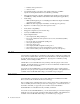
Chapter 1. System Overview IBM® PC 300® GL personal computer types 6563, 6564, and 6574 and PC 300PL personal computer type 6565 are computer systems that provide state-of-the-art computer power with room for future growth.
— Diskette write-protection™ — Alert on LAN • Accelerated graphics port (AGP) video adapter with up to 16 MB of Synchronous Graphics Random Access Memory (SGRAM) • Integrated 16-bit audio controller and built-in high-quality speaker (supports SoundBlaster, Adlib, and Microsoft® Windows® Sound System applications) • Networking — IBM 10/100 megabits-per-second (Mbps) PCI Ethernet adapter with Wake on LAN in some models — IBM PCI token-ring adapter with Wake on LAN support (optional) • Expansion: four d
ADSL modems ADSL modems, available on some models, enable simultaneous internet connectivity and telephone service. Contact your local telephone service provider and ask if your premises need any additional telephony equipment, such as a splitter or a filter. Also contact your Internet service provider (ISP) to determine if they provide service to customers with ADSL. ADSL modems work by using separately the individual four or six wires in the standard RJ-11 telephone jack.
4 PC 300 GL and 300 PL
Chapter 2. System board features This section includes information about system board features. For an illustration of the system board, see “Physical layout” on page 14. Intel Pentium III microprocessor with MMX technology PC 300 GL personal computer types 6563, 6564, and 6574 and PC 300 PL personal computer type 6565 come with an Intel Pentium III microprocessor. The microprocessor has an attached heat sink which plugs directly into a connector on the system board.
For memory expansion, the system board provides two dual inline memory module (DIMM) connectors and supports 133 MHz DIMMs in sizes of 64 MB, 125 MB, and 512 MB. 100 MHz DIMMs may be used in systems with a 100 MHz FSB. The following information applies to system memory: • Synchronous dynamic random access memory (SDRAM) is standard. • The maximum height of memory modules is 6.35 cm (2.5 in.). • Only PC 100 and PC 133 industry-standard, gold-lead DIMMs are supported.
PCI Bus The PCI bus originates in the chip set.
• Support for up to five-meter cable length from host to hub or hub to hub • Guaranteed bandwidth and low latencies appropriate for specific devices • Wide range of packet sizes • Limited power to hubs For information on the connector pin assignment for the USB interface, see “USB port connectors” on page 44. Video Subsystem The PC 300GL personal computer types 6563, 6564, and 6574 ad PC 300PL personal computer type 6565 come with one of the following graphic solutions: 1.
The integrated video subsystem supports all video graphics array (VGA) modes and is compliant with super video graphics array (SVGA) modes and Video Electronics Standards Association (VESA) 1.2.
The PC 300GL personal computer types 6563, 6564, and 6574 and the PC 300PL type 6565 support the following video subsystem modes. Table 3. Supported VGA video modes Sweep Refresh rate rate (kHz) (Hz) Display mode Screen resolution 00 Text 40 x 25 characters 2 B8000 28.322 31.5 70 01 Text 40 x 25 characters 16 B8000 28.322 31.5 70 02 Text 80 x 25 characters Black/white B8000 28.322 31.5 70 03 Text 80 x 25 characters 16 B8000 28.322 31.
These speakers must be powered with a built in amplifier. In general, any powered speakers designed for use with personal computers can be used with the audio adapter. These speakers are available with a wide range of features and power outputs. • Line In port for connecting musical devices, such as a portable CD-ROM player or stereo. • Microphone for connecting a microphone.
The following figure shows the serial port assignments in the configuration. Table 4. Serial port assignments Port assignment Address range (hex) IRQ level Serial 1 03F8–03FF IRQ4 Serial 2 02F8–02FF IRQ3 Serial 3 03E8–03FF IRQ4 Serial 4 O2E8–027F IRQ13 The default setting for the serial port is COM1. Parallel port Integrated in the system board is support for extended capabilities port (ECP), enhanced parallel port (EPP), and standard parallel port (SPP) modes.
Network connection Some PC 300 GL and PC 300 PL models are equipped with an Ethernet or token-ring adapter that supports the Wake on LAN feature.
For information on the connector pin assignments, see “PCI connectors” on page 40. Note: PC 300GL computers do not support ISA expansion adapters or the IBM PCMCIA adapter for PCI. Physical layout The system board might look slightly different from the one shown. Note: 14 PC 300 GL and 300 PL A diagram of the system board, including switch and jumper settings, is attached to the underside of the computer cover.
Þ1ÝMicroprocessor Þ2ÝDIMM 0 Þ3ÝDIMM 1 Þ4ÝFan connector Þ5ÝPower connector Þ6ÝSwitch/LED connector Þ7ÝRFID connector (some models) Þ8ÝPrimary EIDE connector Þ9ÝSecondary EIDE connector Þ10ÝDiskette drive connector Þ11ÝFan connector Þ12ÝLarge rocker switch (some models) Þ13ÝSmall rocker switch Þ14ÝBattery Þ15ÝChassis intrusion detection connector Þ16ÝWake on LAN connector Þ17ÝAlert on LAN connector Þ18ÝCD-ROM, CD-RW, or DVD drive connector Þ19ÝPCI adapter slot 1 Þ20ÝPCI adapter slot 2 Þ21ÝPCI adapter slot 3
Table 6.
Table 6. Large rocker switch settings Microprocessor speed 466 1 2 3 4 5 6 7 8 Off On Off On Off Off Off Off Off On Off Off Off Off Off Off Off Off On On Off Off Off Off Off Off Off On Off Off Off Off 700 933 500 750 1000 533 800 1066 Reserved The small rocker switch has three functions. By moving switch 1 to the On position, you activate the diskette write-protect feature. By moving switch 2 to the On position, you clear the CMOS.
The following illustration shows the connector panel for the desktop model.
The following illustration shows the connector panel for the tower model. Serial 2 Serial 1 2 1 Mouse Keyboard USB 2 2 1 USB 1 Line In Headphone/ Line Out Microphone Parallel SVGA Monitor DVI Monitor Chapter 2.
20 PC 300 GL and 300 PL
Chapter 3. Physical specifications This chapter lists the physical specifications for the PC 300GL personal computer types 6563, 6564, and 6574 and PC 300 PL personal computer type 6565. The PC 300GL ad PC300PL have four expansion slots and four drive bays. Note: The PC 300GL and PC 300PL computers comply with FCC Class B specifications. PC 300 GL and PL desktop Dimensions • • • Height: 138 mm (5.4 in.) Width: 400 mm (15.75 in.) Depth: 429 mm (16.9 in.) Weight • • Minimum configuration as shipped: 9.
Note: Power consumption and heat output vary depending on the number and type of optional features installed and the power-management optional features in use. Heat output • Approximate heat output in British thermal units (Btu) per hour: — Minimum configuration: 256 Btu/hr (75 watts) — Maximum configuration: 706 Btu/hr (207 watts) Airflow • Approximately 0.
– Minimum: 90 V ac – Maximum: 137 V ac – Input frequency range: 57 – 63 Hz – Voltage switch setting: 115 V ac — High Range: – Minimum: 180 V ac – Maximum: 265 V ac – Input frequency range: 47 – 53 Hz – Voltage switch setting: 230 V ac — Input kilovolt-amperes (kVA) (approximately): – – Note: Minimum configuration as shipped: 0.08 kVA Maximum configuration: 0.
24 PC 300 GL and 300 PL
Chapter 4. Power supply A 145-watt power supply drives your computer. The power supply provides 3.3-volt power for the Pentium III microprocessor, core chip set, and 5-volt power for PCI adapters. Also included is an auxiliary 5-volt (AUX 5) power supply to provide power to power-management circuitry and a Wake on LAN adapter.
Component outputs The power supply provides separate voltage sources for the system board and internal storage devices. The following figures show the approximate power that is provided for specific system components. Many components draw less current than the maximum shown. Table 10. System board Supply voltage Maximum current Tolerance +3.3 V dc 5000 mA +5.0% to -5.0% +5.0 V dc 6000 mA +5.0 to -4.0% +12.0 V dc 25.0 mA +5.0% to -5.0% -12.0 V dc 25.0 mA +10.0% to -9.
Table 15. Internal DASD Supply voltage Maximum current Tolerance +12.0 V dc 1500 mA at startup, 400 mA when active +5.0% to -5.0% Table 16. Video port pin 9 Supply voltage Maximum current Tolerance +5.0 V dc 1100 mA +5.0% to -5.0% Note: Some adapters and hard disk drives draw more current than the rated maximums. These adapters and drives can be installed in the system; however, the power supply will shut down if the total power used exceeds the maximum power that is available.
28 PC 300 GL and 300 PL
Chapter 5. System software This section briefly describes some of the system software included with your computer. BIOS Your personal computer uses the IBM basic input/output system (BIOS), which is stored in flash electrically erasable programmable read-only memory (EEPROM). Some features of the BIOS are: • • • • • • • • • • • • • • • • • PCI support according to PCI BIOS Specification 2.2 Microsoft PCI IRQ Routing Table Plug and Play support according to Plug and Play BIOS Specification 1.
Configuration/Setup Utility program The Configuration/Setup Utility program provides menu choices for devices, I/O ports, date and time, system security, start options, advanced setup, and power management. More detailed information on using the Configuration/Setup Utility program is in the PC 300GL and PC 300PL User Guide. Advanced Power Management (APM) The PC 300GL computers have built-in energy-saving capabilities.
Chapter 6. System compatibility This chapter discusses some of the hardware, software, and BIOS compatibility issues for the computer. See the Compatibility Report under, “Related publications” on page vii for a list of compatible hardware and software options. Hardware compatibility This section discusses hardware, software, and BIOS compatibility that must be considered when designing application programs.
3. Sends the EOI 4. Waits one I/O delay 5. Enables the interrupt through the Set Interrupt Enable Flag command Hardware interrupt IRQ9 is defined as the replacement interrupt level for the cascade level IRQ2. Program interrupt sharing is implemented on IRQ2, interrupt hex 0A. The following processing occurs to maintain compatibility with the IRQ2 used by IBM Personal Computer products: 1. A device drives the interrupt request active on IRQ2 of the channel. 2.
Appendix A. Connector pin assignments The following figures show the pin assignments for various system board connectors. SVGA monitor connector 5 1 10 6 15 11 Table 17.
DVI-I monitor connector C1 1 C2 C3 C4 C5 Table 18.
Table 20.
Table 20.
Table 20.
Table 21.
Table 21.
PCI connectors A1 A62 A2 B1 B62 B2 Table 22.
Table 22. PCI connector pin assignments Pin Signal I/O Pin Signal I/O A28 Address/data 22 I/O B28 Ground N/A A29 Address/data 20 I/O B29 Address/data 21 I/O A30 Ground I/O B30 Address/data 19 N/A A31 Address/data 18 I/O B31 +3.3 V dc N/A A32 Address/data 16 I/O B32 Address/data 17 I/O A33 +3.3 V dc N/A B33 C/BE2# I/O A34 FRAME# I/O B34 Ground N/A A35 Ground N/A B35 IRDY# I/O A36 TRDY# I/O B36 +3.
IDE connectors 2 40 1 39 Table 23.
Diskette drive connector 2 34 1 33 Table 24.
Power supply connector Table 25. Power supply connector pin assignments Pin Signal Function Pin Signal Function 1 3.3 V dc +3.3 V dc 11 3.3 V dc +3.3 V dc 2 3.3 V dc +3.
Mouse and keyboard port connectors 6 5 4 3 1 2 Table 28. Mouse port connector pin assignments Pin Signal I/O Pin Signal I/O 1 Data I/O 4 +5 V dc N/A 2 Reserved I/O 5 Clock I/O 3 Ground N/A 6 Reserved N/A Pin Signal I/O Table 29. Keyboard port connector pin assignments Pin Signal I/O 1 Keyboard data I/O 4 +5 V dc N/A 2 Mouse data I/O 5 Keyboard Clock I/O 3 Ground N/A 6 Mouse clock N/A Serial port connector 5 1 6 9 Table 30.
Parallel port connector 1 13 25 14 Table 31.
Appendix B. System address maps The following charts represent how the hard disk stores different types of information. Address ranges and byte sizes are approximate. System memory map The first 640 KB of system board RAM is mapped starting at address hex 0000000. A 256 byte area and a 1 KB area of this RAM are reserved for BIOS data areas. Memory can be mapped differently if POST detects an error. Table 32.
Input/output address map The following lists resource assignments for the I/O address map. Any addresses that are not shown are reserved. Table 33.
Table 33.
DMA I/O address map Table 34.
Table 34.
52 PC 300 GL and 300 PL
Appendix C. IRQ and DMA channel assignments The following tables list the interrupt request (IRQ) and direct memory access (DMA channel assignments. Table 36.
Table 37.
Appendix D. Error codes Complete lists of POST and beep error codes are provided in the PC300GL and PC 300PL User Guide and in the Hardware Maintenance Manual. POST error codes POST error messages appear when, during startup, POST finds problems with the hardware or a change in the hardware configuration. POST error messages are 3-, 4-, 5-, 8-, or 12-character alphanumeric messages. Beep codes Beep codes are a series of tones in sets of two or three that sound when there are POST errors.
56 PC 300 GL and 300 PL
Appendix E. Notices and Trademarks This publication was developed for products and services offered in the U.S.A. IBM may not offer the products, services, or features discussed in this document in other countries. Consult your local IBM representative for information on the products and services currently available in your area. Any reference to an IBM product, program, or service is not intended to state or imply that only that IBM product, program, or service may be used.
Other company, product, and service names may be trademarks or service marks of others.
Bibliography • PCI BIOS Specification 2.0, Source: PCI Special Interest Group • Plug and Play BIOS Specification 1.1, Source: Microsoft Corporation; http://www.microsoft.com/hwdev/ • Advanced Power Management (APM) BIOS Interface Specification 1.
60 PC 300 GL and 300 PL
Index A D K Accelerated Graphics Port 8 ACPI 30 address maps DMA I/O 50 input/output 48 PCI configuration 51 system memory 47 Adlib 10 ADSL modems 3 Advanced Configuration and Power Interface 30 Advanced Power Management 30 AGP 8 APM 30 audio connectors 10 controller 10 device drivers 10 subsystem 10 DDC 9 DIMM 6 direct memory access 7 diskette drive connector 43 interface 11 DMA 7 DMA I/O address map 50 dual inline memory module 6 DVD-ROM 2 DVI-I connector 34 interface 8 keyboard port connector 45 kil
Rocker Switches 15 S serial port connector 45 Serial ports 11 shutdown 27 SMID 1 software CDs 30 compatibility 32 diagnostic program 30 system 29 SoundBlaster 10 specifications desktop 21 tower 22 SPP 12 standard parallel port 12 SVGA monitor connector 33 system board 5, 14 system memory map 47 T terminology viii token ring 13 U UART 11 Universal Serial Bus 7 USB interface 7 port connectors 44 V VGA 9 video DVI-I 34 frames per second 8 graphic solutions 8 graphics array 9 modes 10 SVGA 33 Video Electron