SAGP-845EV User Manual Version 2.0 SOCKET 478 PENTIUM 4/4-M with 10/100 Ethernet LAN & AGP4X VGA SBC March 1, 2004 ©Copyright 2004 by ICP Electronics Inc. All rights Reserved.
Copyright Notice The information in this document is subjected to change without prior notice in order to improve reliability, design and function and does not represent a commitment on the part of the manufacturer. In no event will the manufacturer be liable for direct, indirect, special, incidental, or consequential damages arising out of the use or inability to use the product or documentation, even if advised of the possibility of such damages.
Table of Contents Chapter 1 1.1 1.2 Specifications ....................................................................................4 Package Contents ..............................................................................6 Chapter 2 2.1 2.2 2.3 2.4 2.5 Connection ......................................................... 9 Floppy Disk Drive Connector.............................................................. 10 Ultra ATA33/66/100 IDE Disk Drive Connector ....................................
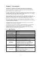
Chapter 1 Introduction SAGP-845EV is a PSB form factor board to work with a high performance processor. It is equipped with advanced multi-mode I/O, and designed for system manufacturers, integrators, or VARs who want to provide reliable and quality performance at a reasonable price. In addition, SAGP-845EV’s onboard Intel 845G MGCH chip features built-in AGP4X capability which provides 3D graphics of up to 2048x1536x16-bit-color resolution. The onboard VGA shares 8MB system DDR-SDRAM.
Configurable to LPT1, LPT2, LPT3 or disabled Supports EPP/ECP/SPP Hardware monitor Monitors power supply voltage and fan speed status Supports Serial Infrared (SIR) and Amplitude Shift IrDA port Keyed IR (ASKIR) interface USB port Supports 4 USB2.0 ports for future expansion − Programmable − Reset generated when CPU does not periodically Watchdog timer trigger the timer − The BIOS routine INT15 can be used to control the watchdog and generate a system reset − Built-in AGP2.
1.2 • • • • • • • • • • Package Contents SAGP-845EV single board computer x 1 FDD cable x 1 ATA/100 IDE cable x 1 ATX-12V cable x 1 PS/2 Y splitter cables for keyboard and mouse connection x 1 Printer cable with bracket x 1 RS-232 serial ports cable with bracket x 2 Audio cable with bracket x 1 Installation Guide CD (user manual included) x 1 Quick Startup Reference x 1 If any of these items are missing or damaged, contact the dealer from whom you purchased this product.
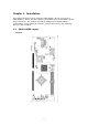
Chapter 2 Installation This chapter describes how to install the SAGP-845EV. At first, the layout of SAGP-845EV is shown, and the unpacking information that you should be careful with is described. The jumpers and switch settings for the SAGP-845EV 's configuration, such as CPU type selection, system clock setting, and watchdog timer, are also included. 2.
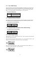
2.2 Clear CMOS Setup If the user wants to clear the CMOS Setup data (for example, the user forgot the password and needed to clear the setup data then set the password again), the user should close the JP2 (set the jumper to 2-3) about 3 seconds, then open it again. For normal operation, set the jumper to 1-2 or open JP2. • JP2: Clear CMOS Setup JP2 1-2 2-3 2.3 Description Keep CMOS Setup (Normal Operation) Clear CMOS Setup Keyboard Power Selection This board can support keyboard wakeup.
Chapter 3 Connection This chapter describes how to connect peripherals, switches and indicators to the SAGP-845EV board.
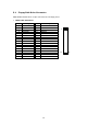
3.1 Floppy Disk Drive Connector SAGP-845EV board has a 34-pin connector for the floppy drive.
3.2 Ultra ATA33/66/100 IDE Disk Drive Connector Each of the SAGP-845EV IDE connectors can have one IDE (Integrated Device Electronics) attached to it.
3.3 Parallel Port This port is usually connected to a printer. SAGP-845EV includes an on-board parallel port accessed through a 26-pin flat-cable. Three modes― SPP, EPP and ECP― are supported.
3.4 Serial Ports SAGP-845EV offers two high speed NS16C550 compatible UARTs with Read/Receive 16-byte FIFO serial ports.
3.5 Keyboard Connector SAGP-845EV provides a 6-pin keyboard/mouse connector. • KBM1: 6-pin Mini-DIN Keyboard/Mouse Connector PIN 1 2 3 4 5 6 3.6 Description KEYBOARD DATA MOUSE DATA GROUND +5V KEYBOARD CLOCK MOUSE CLOCK USB Port Connector SAGP-845EV provides 4 built-in USB2.0 ports for future I/O bus expansion. • USB1 & USB2 (single port) PIN 1 2 3 4 • Description VCC DATADATA+ GROUND USB3 (dual port) Provides two sets (pins 1/3/5/7 and 2/4/6/8) of USB connectors. PIN 1 3 5 7 3.
3.8 Fan Connector SAGP-845EV provides three CPU cooling fan connectors, which supply 12V/500mA. • FAN1/FAN2/FAN3: CPU Fan Connector PIN 3 2 1 Description Sensor 12V Ground 3 2 1 3.9 LAN RJ45 Connector SAGP-845EV is equipped with a built-in 10/100Mbps Ethernet controller. You can connect it to your LAN through RJ45 connector.
3.11 Audio Connectors SAGP-845EV has an onboard audio controller (CMEDIA CMI8738LX) that connects input and output devices through pin-headers (CN4). The audio controller supports 5.1 channel sounds including LINEOUT, REAR, and CENTER/BASS. CD-IN (CDIN1). • CN4: Audio Connector (2x8_2.
3.12 Compact Flash Storage Card Socket SAGP-845EV configures Compact Flash Storage Card to IDE mode. This type II Socket is compatible with IBM Micro Drive.
3.13 External Switches and Indicators There are several external switches and indicators for monitoring and controlling your CPU board. All the functions are integrated in CN2 connector.
Chapter 4 Award BIOS Setup 4.1 Introduction This chapter discusses the setup program in the BIOS. It will give users a stepby-step guidance to configure the system. The user-defined configuration is then stored in the battery-backed CMOS RAM, which retains the customized information while the power is off. 4.2 Starting Setup The BIOS is immediately active when the computer has been turned on. While the BIOS is in control, the setup program will be activated by one of the following ways: a.
4.3 Using Setup In general, the arrow keys are used to highlight items, and then press to select the item. The following table provides more details about how to navigate in the setup program using the keyboard. Key Up Arrow Down Arrow Left Arrow Right Arrow Esc Move Enter PgUp key PgDn key + key - key Esc key F1 key F5 key F6 key F7 key F10 key 4.
4.4.1 Setup Items The main menu includes the following main setup categories. Recall that some systems may not include all entries. Standard CMOS Features Use this menu for basic system configuration. See Section 4.5 for the details. Advanced BIOS Features Use this menu to set the advanced features available on the system. See Section 4.6 for the details. Advanced Chipset Features Use this menu to change the values in the chipset registers and optimize the system's performance. See section 4.
4.5 Standard CMOS Setup The items in Standard CMOS Setup Menu are divided into 10 categories. Each category includes none, one or more than one setup items. Use the arrow keys to highlight the item and then use the or keys to select the wanted value for each item.
Main Menu Selections Item Date Time IDE Primary Master Options MM DD YYYY HH : MM : SS Options are in its sub menu (Described in Table 2) IDE Primary Slave Options are in its sub menu (Described in Table 2) IDE Secondary Master Options are in its sub menu (Described in Table 2) IDE Secondary Slave Options are in its sub menu (Described in Table 2) Drive A Drive B Base Memory None 360K, 5.25 in 1.2M, 5.25 in 720K, 3.5 in 1.44M, 3.5 in 2.88M, 3.
IDE Adapters The IDE adapters control the hard disk drive. Use a separate sub menu to configure each hard disk drive. Figure 2 shows the IDE primary master sub menu. CMOS Setup Utility – Copyright © 1984-2000 Award Software IDE Primary Master IDE HDD Auto-Detection Press Enter Item Help Menu Level ¾¾ IDE Primary Master Auto Access Mode Auto To auto-detect the HDD’s Capacity 15362 MB size, head...
4.6 Advanced BIOS Features This section allows users to configure the system for basic operation. The options for the system’s default speed, boot-up sequence, keyboard operation, shadowing and security are available.
Virus Warning Allows users to choose the VIRUS Warning feature for IDE Hard Disk boot sector protection. If this function is enabled and someone attempts to write data into this area, BIOS will show a warning message on screen and alarm beep will be heard. Enabled Disabled Activates automatically when the system boots up causing a warning message to appear when anything attempts to access the boot sector or hard disk partition table.
Boot Up NumLock Status Select power on state for NumLock. The choice: On/Off. Gate A20 Option Select if chipset or keyboard controller should control GateA20. Normal Fast A pin in the keyboard controller controls GateA20 Lets chipset control GateA20 Typematic Rate Setting Key strokes repeat at a rate determined by the keyboard controller. When enabled, the typematic rate and typematic delay can be selected. The choice: Enabled/Disabled.
Report No FDD For Win 95 Whether report no FDD for Win 95 or not. The choice: Yes, No. Small Logo (EPA) Show Disabled/Enabled Small Logo (EPA) Show.
4.7 Advanced Chipset Features CMOS Setup Utility – Copyright © 1984 – 2000 Award Software Advanced Chipset Features DRAM Timing Selectable By SPD Item Help CAS Latency Time 1.
DRAM RAS# to CAS# Delay • • • • This field lets users insert a timing delay between the CAS and RAS strobe signals. It is used when DRAM is written to, read from, or refreshed. Choice 2 means shorter delay which shortens the process of charging; and choice 3 means longer delay which lengthens the process of charging. This field applies only if the synchronous DRAM is installed in the system. The choice: 2, 3.
On-chip VGA Enabled/Disabled On-chip VGA Flash BIOS Disabled/Enabled Flash BIOS 4.
IDE Primary/Secondary Master/Slave UDMA Ultra DMA-33/66 implementation is possible only if the IDE hard drive supports it and the operating environment includes a DMA driver (Windows 95 OSR2 or a third-party IDE bus master driver). If your hard drive and your system software both support Ultra DMA-33/66, select Auto to enable BIOS support. The Choice: Auto, Disabled. USB Controller Select Enabled if the system contains a Universal Serial Bus (USB) controller. The Choice: Enabled, Disabled.
Watchdog Timer Unit Select the Watchdog Timer unit. The choice: Second, Minute. 4.9 Power Management Setup The Power Management Setup allows the user to configure the system to the most effective energy save.
Power Management This category allows the user to select the type (or degree) of power saving related to the following modes: 1. HDD Power Down 2. Doze Mode 3. Suspend Mode There are four selections for Power Management, three of which have fixed mode settings. Disable (default) Min. Power Saving Max. Power Saving User Defined No power management. Disables all four modes • Minimum power management • Doze Mode = 1 hr. • Standby Mode = 1 hr. • Suspend Mode = 1 hr. • HDD Power Down = 15 min.
HDD Power Down When enabled and after the set time of system inactivity, the hard disk drive will be powered down while all other devices remain active. The choice: 1Min, 2Min, 3Min, 4Min, 5Min, 6Min, 7Min, 8Min, 9Min, 10Min, 11Min, 12Min, 13Min, 14Min, 15Min, Disabled. PM EVENTS PM events are I/O events whose occurrence can prevent the system from entering a power saving mode or can awaken the system from such a mode.
4.10 PnP/PCI Configuration Setup This section describes configuring the PCI bus system. PCI stands for Personal Computer Interconnect. It is a system which allows I/O devices to operate at speeds nearing the speed the CPU itself uses when communicating with its own special components. This section covers some specific technical settings and it is strongly recommended that only experienced users should make any changes to the default settings.
IRQ3/4/5/7/9/10/11/12/14/15 assigned to This item allows the user to determine the IRQ assigned to the ISA bus and is not available to any PCI slot. Legacy ISA for devices compliant with the original PC AT bus specification, PCI/ISA PnP for devices compliant with the Plug and Play standard whether designed for PCI or ISA bus architecture. The choice: PCI Device, Reserved. PCI/VGA Palette Snoop Leave this field disabled. The choice: Enabled, Disabled. 4.
4.12 Frequency/Voltage Control CMOS Setup Utility – Copyright © 1984-2000 Award Software Frequency/Voltage Control CPU Clock Ratio 8X Item Help Auto Detect PCI Clk Enabled ------------------------Spread Spectrum Disabled Menu Level ¾ CPU Host/3V66/PCI Clock Default ↑↓←→ Move Enter: Select +/-/PU/PD: Value F10:Save ESC: Exit F1: General Help F5: Previous Values F6: Fail-safe defaults F7: Optimized Defaults Auto Detect PCI Clk This item allows the users to enable/disable auto detect DIMM/PCI Clock.
4.13 Defaults Menu Selecting “Defaults” from the main menu will bring up the two options described below. Load Fail-Safe Defaults If the user presses on this item, a dialog box with a message similar to the following will pop up: Load Fail-Safe Defaults (Y/N) ? N Pressing ‘Y’ loads the BIOS default values for the most stable, minimalperformance system operations.
4.14 Supervisor/User Password Setting The user can set the password for either supervisor or user, or for both of them. Supervisor password: for entering and changing the settings of the system User password: for just entering the system but does not have the privilege to change any settings of the system If this function is enabled, the following message will appear to guide the user to create a password. ENTER PASSWORD: Type the password, up to eight characters in length, and press .
4.15 Exit Selecting Save & Exit Setup Pressing on this item asks for confirmation: Save to CMOS and EXIT (Y/N)? Y Pressing “Y” stores the selections made in the menus in CMOS – a special section of memory that stays on after the system has been turned off. When the computer reboots again, the BIOS configures the system according to the Setup selections stored in CMOS.
Appendix A Watchdog Timer The Watchdog Timer is provided to ensure that standalone systems can always recover from catastrophic conditions that cause the CPU to crash. This condition may have occurred by external EMI or a software bug. When the CPU stops working correctly, hardware on the board will either perform a hardware reset (cold boot) or a Non-Maskable Interrupt (NMI) to bring the system back to a known state.
Appendix B Address Mapping IO Address Map I/O address Range 000-01F 020-021 040-05F 060-06F 070-07F 080-09F 0A0-0A1 0C0-0DF 0F0-0FF 1F0-1F7 2F8-2FF 378-37F 3B0-3BF 3C0-3DF 3F6-3F6 3F7-3F7 3F8-3FF Description DMA Controller Interrupt Controller System time Keyboard Controller System CMOS/Real time Clock DMA Controller Interrupt Controller DMA Controller Numeric data processor Primary IDE Channel Serial Port 2 (COM2) Parallel Printer Port 1 (LPT1) Intel(R) 82815 Graphics Controller Intel(R) 82815 Graphics
1st MB Memory Address Map Memory address 00000-9FFFF A0000-BFFFF F0000-FFFFF 1000000- Description System memory VGA buffer System BIOS Extend BIOS IRQ Mapping Table IRQ0 IRQ1 IRQ2 IRQ3 IRQ4 IRQ5 IRQ6 IRQ7 System Timer Keyboard Available COM2 COM1 Available FDC Available IRQ8 IRQ9 IRQ10 IRQ11 IRQ12 IRQ13 IRQ14 IRQ15 RTC clock USB2.
Appendix C How to Upgrade a New BIOS Note: Before flashing BIOS, please enable the item “FLASH BIOS” in BIOS setting. The user can install an upgrade BIOS for the SAGP-845EV download from the manufacturer’s web site (http://www.ieiworld.com). New BIOS may provide support for new peripherals, improvements in performance or fixes to addressed known bugs. BIOS Update Procedure: 1. Make a boot disk.
new BIOS file WITHOUT a warning prompt. A simple file name for saving the old BIOS to is OLDBIOS.BIN. 9. Your second option, in sequence, will be whether you want to flash your BIOS. Enter Y (for "yes"). Note: This is the critical step. Once you kit the enter key, do NOT touch the keyboard, the reset button, or power switch while the flashing is in progress. There will be bar progressing across the screen while the flashing is progressing. 10.
Appendix D AGP Slot This IPC CPU Card has an Accelerated Graphics Port (AGP) slot that supports +1.5V AGP card. When you buy an AGP card, make sure that you ask for one with +1.5V specification. Note the notches on the card golden fingers to ensure that they fit the AGP slot on your ICP CPU card.