
Instruction Manual

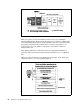

Firmware Core Brings the system up to where the compressed image has been
decompressed and running
Virtual Disk Contains the firmware modules required to support each hardware
subsystem
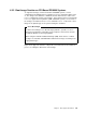
4.4.1 Firmware Boot Sequence
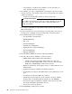
This section describes the firmware booting process on PCI-based RS/6000. This
is also shown on Figure 25.
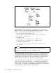
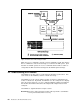
Figure 25. Firmware Boot Sequence
When the system is powered-on, the hardware passes control to the storage
address 0xfff00100, the firmware entry point.
1. The firmware's first task is to perform a processor POST (Power-On Self Test).
An uncompressed instruction resides on the entry point of the firmware. If the
processor fails to execute this branch instruction, the next instruction is
executed.
If it fails, the system stops.
2. The 60x registers are initialized.
If it fails, the system stops and appears to be doing nothing, but cooling
fans might be observed running.
3. The firmware initializes the memory controller, and 2 KB of good memory is
found.
If it fails, the hard file LED is turned on, and the system stops.
4. A short beep is given on the speaker.
5. A Cyclic Redundancy Check (CRC) is performed on the compressed firmware.
Chapter 4. Boot Support and Firmware 65