ThinkPad s30, s31 Hardware Maintenance Manual
Before using this information and the product it supports, be sure to read the general information under “Read This First” on page 1.
Contents ThinkPad s30, s31 Hardware Maintenance Manual Read This First . . . . . . . . . . . . What to Do First . . . . . . . . . . How to Disable the Password . . . . . . Product Overview . . . . . . . . . . . Fn Key Combinations . . . . . . . . . Status Indicators . . . . . . . . . . Related service information . . . . . . . . Restoring the pre-installed software . . . . . Creating the service partition for the s30 series . To create a recovery repair diskette . . . . .
1055 Modem Cable ASM . . . . 1060 Wireless Card ASM (s30 only) . 1065 IEEE 1394/LAN Card ASM . . 1070 IEEE 1394/LAN Card Cable ASM 1075 DIMM Card ASM . . . . . 1080 Upper Cover ASM . . . . . 1085 Speaker ASM . . . . . . 1090 Palm Rest ASM. . . . . . 1100 Fan ASM. . . . . . . . 1130 PCMCIA Slots . . . . . . 1140 System Board . . . . . . 1145 Power Board ASM . . . . . 1150 LCD Bezel ASM . . . . . 1155 LCD Rear Cover ASM . . . . 1160 LCD Inverter ASM . . . . . 1170 LCD FPC ASM . . . . . . 1180 LCD Panel ASM .
ThinkPad s30, s31 Hardware Maintenance Manual About This Manual This manual contains service and reference information for the IBM ThinkPad s30 and s31products. Use this manual along with the diagnostics tests to troubleshoot problems effectively. The manual is divided into sections as follows: v The introduction section provides general information, guidelines, and safety information required to service computers.
this is suspected, clear the error log and run the test again. Do not replace any FRUs if log errors do not reappear. Be careful not to replace a non-defective FRU. What to Do First The servicer must include the following in the parts exchange form or parts return form that is attached to the returned FRU: 1. Name and phone number of servicer 2. Date of service 3. Date when part failed 4. Date of purchase 5. Failure symptoms, error codes appearing on the display, and beep symptoms 6.
v Sticky keys caused by spilling liquid onto the keyboard The following symptoms might indicate damage caused by non-warranted activities: v Missing parts might be a symptom of unauthorized service or modification. v Hard disk drive spindles can become noisy from being subjected to excessive force or from being dropped. How to Disable the Password There are three passwords used at a typical customer site: the Supervisor Password, the hard disk drive password, and the Power On password.
Product Overview The following shows an overview of the system features of the ThinkPad s30 and s31 series. Feature Description Processor Intel Mobile Pentium III 600 MHz, 128 KB L2 cache Bus architecture PCI Bus Memory 128 MB SDRAM onboard 32 MB, 64 MB or 128 MB DIMM card (max. 256 MB) BIOS ROM up to 512 Kbytes Video v 10.
Fn + Result F4 Suspend mode F7 Switch between the LCD, the external monitor, and both the LCD and external monitor. F12 Hibernation mode Insert Increases the volume Delete Decreases the volume Backspace Mutes the internal speaker Home Increase brightness End Decrease brightness PgUp Toggle ThinkLight on/off Spacebar Enables the FullScreen Magnifier (s31 only) Note: Some models use the three volume control buttons to adjust the volume.
Symbol Color Meaning (1) Battery status Green Enough battery power remains for operation. Blinking orange The battery pack needs to be charged. Orange The battery pack is being charged. Blinking green The battery pack is being charged and is almost fully charged. Green The computer is in suspend mode. Blinking green The computer is entering suspend mode. (3) Drive in use Green Data is being read from or written to the hard disk drive.
Related service information This section provides information about restoring the pre-installed software. Restoring the pre-installed software To restore the pre-installed software for the s30 you can use either the Product Recovery Program or a Recovery CD. To restore the pre-installed software for the s31 you can only use the Product Recovery Program. The Product Recovery Program is in a section of the hard disk drive (the Service Partition) that is not displayed by Windows Explorer.
3. A menu will appear stating ″Your computer originally included a Product Recovery program...Reinstall the Product Recovery Program? (Y/N)″. Note: If the hard-disk drive contains any partitions, you will not receive this menu-go to step 1. 4. Enter ″Y″ and the Service Partition will be created and loaded with D2D files. Note: If you do not want to create the Service Partition, press ″N″, and then go to step 8. 5. Press Enter at the next window to continue. The Service Partition is created.
3. At the prompt, press F11. (The option to press F11 appears for only a few seconds. You must press F11 quickly). The Product Recovery program main menu appears. 4. If you are using Windows 2000 Professional, you will be prompted to select the appropriate operating system setting. This menu does not appear for Windows 98 SE. 5. Select System Utilities from the main menu. Press Enter. 6. Select Create a Recovery Repair diskette. Press Enter. 7. Follow the on-screen instructions. 8.
Symptoms (Verified) Go to Power failure. (The power-on indicator does not go on or stay on.) “Power System Checkout” on page 14, then use table in “Power-Related Symptoms” on page 23. POST does not complete. No beeps or error codes/messages are indicated. “Symptom-to-FRU Index” on page 19, then use table in “No Beep Symptoms” on page 22. POST beeps, but no error codes are displayed. “Symptom-to-FRU Index” on page 19. POST detected an error and displayed numeric error codes.
Note: The pull-down menu differs depending on the model. 4. Run the applicable function test. 5. Follow the instructions on the screen. If there is a problem, PC-Doctor shows some messages. 6. Reseat the cable or connector of the detected FRU and run the test again. If the error recurs, replace the FRU that caused the error. Note: With some FRUs, especially the system board, the problem may be caused by peripheral FRUs.
If the distance between the Access Point and the system is too far, the test may report failure even if the device is properly working. If the encryption is enabled on the Access Point, the test program cannot properly communicate with the Access Point to test the device, and will report failure. Due to the nature of wireless connection, the test may report failure with ″No LinkTest response received″ error message in the log, even if the device is working properly.
1. Replace the keyboard. 2. Replace the system board. The following auxiliary input devices are supported for this computer: v Numeric keypad v Mouse (USB-compatible) v External keyboard (USB-compatible) If any of these devices do not work, reseat the cable connector and repeat the failing operation. If the problem does not reoccur, replace the device and then the system board. Memory Checkout DIMM are available for increasing memory capacity.
1. Boot from the diagnostics diskette and start the program. 2. Go to Diagnostics on the main menu and select Other Devices. 3. Follow the description in the window. 4. If the test detects a problem, replace the board. Power System Checkout To verify the symptom of the problem power on the computer using each of the following power sources: 1. Remove the battery ASM. 2. Connect the AC Adapter and check that power is supplied. 3.
If the voltage is within the range, do the following: v Replace the system board. v If the problem is not corrected, go to “Undetermined Problems” on page 25. Note: An audible noise from the AC Adapter does not always indicate a defective adapter. Checking the Operational Charging To check operational charging, use a discharged battery pack (battery ASM) or a battery ASM that has less than 50% of the total power remaining when installed in the computer. Perform operational charging.
3. If the voltage is less than 10.6V, the battery ASM has been discharged, recharge the battery ASM. If the voltage is still less than 10.6V, replace the battery. TrackPoint Checkout If the external mouse is connected, the TrackPoint does not work. In this case, please detach the external mouse to check the TrackPoint. If this does not correct the TrackPoint problem, continue with the following: After you use the TrackPoint, the pointer drifts on the screen for a short time.
Suspend Mode In suspend mode, the following occurs: v The LCD is powered off. v The hard disk drive is powered off. v The CPU stops. Events that cause the computer to enter suspend mode: v Suspend mode requested by the Fn key (Fn+F4). v The Lid is closed. v The specified time has elapsed. v Battery low occurs and hibernation conditions are insufficient. Note: When battery is low, the battery status indicator blinks orange.
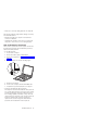
The computer exits hibernation mode and resumes operation when the power-on switch is pressed. When power is turned on, the hibernation file in the boot record on the hard disk drive is read and the system status is restored from the hard disk drive. The power switch must be pressed to cause the computer to resume operation from hibernation mode. How to Create the Hibernation Function: Do as follows: v Turn off the computer. v Connect the USB diskette drive to the computer.
Symptom-to-FRU Index The Symptom-to-FRU Index lists the symptoms and errors and the possible causes. The most likely cause is listed first. Note: Perform the FRU replacement or actions in the sequence shown in the FRU/Action columns. If a FRU replacement does not solve the problem, put the original part back in the computer. Do not replace a non-defective FRU. This index can also be used to help you decide the next possible FRUs to be replaced when servicing a computer.
Symptom/Error FRU/Action in Sequence 0212 Go to “Keyboard and Auxiliary Input Device Checkout” on page 12. Keyboard Controller Failed 0213 Unlock external keyboard. Keyboard locked — Unlock key switch Load Setup Defaults in BIOS Setup Utility. 0220 Monitor type does not match CMOS — Run Setup System board 0230 Shadow RAM Failed at offset:nnnn 0231 1. DIMM System RAM Failed at offset:nnnn 2. System board 0232 1. DIMM Extended RAM Failed at offset:nnnn 2.
Symptom/Error FRU/Action in Sequence 0281 1. Load Setup Defaults in the BIOS Setup Utility. Memory size found by POST differed from CMOS 02D0 2. DIMM 3. System board System board System cache error — Cache disabled 02F0 System board CPU ID: 02F5 1. DIMM DMA Test Failed 2. System board 02F6 1. DIMM Software NMI Failed 2. System board 02F7 1. DIMM Fail-Safe Timer NMI Failed 2. System board Error Messages Symptom/Error FRU/Action in Sequence Device Address Conflict 1.
Symptom/Error FRU/Action in Sequence Operating system not found 1. Check that the operating system has no failure and is installed correctly. 2. Enter IBM BIOS Setup Utility and see whether the hard disk drive and the diskette drive are properly installed. 3. Diskette drive 4. Hard disk drive 5. System board No Beep Symptoms Symptom/Error FRU/Action in Sequence No beep, power-on indicator on, LCD blank, no POST 1. Ensure every connector is connected tightly and correctly. 2. DIMM 3.
Keyboard-Related Symptoms Symptom/Error FRU/Action in Sequence Keyboard (one or more keys) doesn’t work. 1. Reseat the keyboard cable. 2. Keyboard 3. System board Indicator-Related Symptoms Symptom/Error FRU/Action in Sequence Indicator incorrectly remains off or on, but system runs correctly. 1. Reseat the keyboard connector. 2. Reseat the LCD-to-system-board connector. 3. System board Power-Related Symptoms Symptom/Error FRU/Action in Sequence Power shuts down during operation. 1. Battery 2.
Speaker-Related Symptoms Symptom/Error FRU/Action in Sequence Speakers make noise or no sound comes from system. 1. Speakers In DOS or Windows multimedia programs, no sound comes from the computer. 1. Speakers 2. System board 2. System board Power Management-Related Symptoms Symptom/Error FRU/Action in Sequence The system will not enter hibernation mode. 1. Keyboard (if control is from the keyboard) 2. Hard disk drive 3. System board The system will not wake up from hibernation mode. 1.
Symptom/Error FRU/Action in Sequence IEEE 1394 does not work 1. IEEE 1394 cable correctly 2. Card-to-system board cable 3. IEEE 1394/LAN card ASM 4. System board Modem does not work correctly 1. Modem cable 2. Modem card ASM 3. System board Ethernet does not work correctly 1. Card-to-system board cable 2. LAN/1394 combo card ASM 3. Base cover ASM 4. System board Wireless LAN does not work correctly (s30 only) 1. Wireless card ASM 2. System board Print problems 1. Run printer self-test. 2.
Verify that the power supply being used at the time of the failure is operating correctly. (See “Power System Checkout” on page 14.) 1. Power off the computer. 2. Visually check for damage. If any problems are found, replace the FRU. 3. Remove or disconnect all of the following devices: a. Non-IBM devices b. Printer, mouse, and other external devices c. Battery ASM d. Hard disk drive e. DIMM f. PC Cards (PCMCIA) 4. Power on the computer. 5. Determine if the problem has changed. 6.
CE Utility Program Diskette Writing the Serialization Information The EEPROM on the system board contains the Serialization Information Data— that is, a system board serial number and a system unit serial number. When you replace the system board, restore the Serialization Information Data using the ThinkPad CE Utility Diskette. The serial number label is attached to the computer.
FRU Removals and Replacements This section contains information about removals and replacements. v Do not damage any parts. Only certified and trained personnel should service the computer. v The arrows in this section show the direction of movement to remove a FRU, or to turn a screw to release the FRU. The arrows are marked in numeric order, in square callouts, to show the correct sequence of removal.
LCD FRU Replacement Notice The TFT LCD (XGA 10.4–inch) for the computer contains many thin-film transistors (TFTs). A small number of missing, discolored, or lighted dots (on all the time) is characteristic of TFT LCD technology, but excessive pixel problems can cause viewing concerns. The LCD should be replaced if the number of missing, discolored, or lighted dots in any background is: 5 or more bright dots, 5 or more dark dots, or a total of 9 or more bright and dark dots.
1010 Battery ASM To remove the battery ASM: 1. Slide the release latch as shown. 2. Remove the battery ASM. Reverse the steps described above when installing a new battery pack.
1020 Keyboard ASM v 1010 Battery ASM To remove the keyboard ASM: 1. Remove the four screws securing the keyboard. 2. Loosen the other three screws: these screws are fixed to the computer. 3. Turn the notebook over; then move the keyboard as shown. 4. Disconnect the keyboard connector from the system board and remove the keyboard. Size Step (Quantity) Head & Color 1 M2.0 x 7L (4) Flat head, black Torque 2.5 kgf-cm 2 N/A N/A 2.0 kgf-cm Note: Make sure you use the correct screw for replacement.
1030 Hard Disk Drive ASM v 1010 Battery ASM v 1020 Keyboard ASM Warning: v Do not drop or apply any shock to the hard disk drive. The hard disk drive is sensitive to physical shock. Incorrect handling can cause damage and permanent loss of data on the drive. v Before removing the drive, have the user make a backup copy of all the information on the drive if possible. v Never remove the drive while the system is operating or is in suspend mode. For the s30 series To remove the hard disk drive ASM: 1.
2. Disconnect the IDE connector from the system board and remove the hard disk drive. For the s31 series To remove the hard disk drive ASM: 1. Slide and lift the drive bracket as shown to remove the bracket. 2. Remove the screw from the HDD/FPC bracket.
3. Remove the HDD/FPC bracket. 4. Disconnect the IDE connector from the system board and remove the hard disk drive. Size Step (Quantity) Head & Color Torque 2 M2.0 x 4L (1) Flat head, black 2.0 kgf-cm Note: Make sure you use the correct screw for replacement.
1035 Hard Disk Drive FPC ASM v 1010 Battery ASM v 1020 Keyboard ASM v 1030 Hard Disk Drive ASM Warning: v Do not drop or apply any shock to the hard disk drive. The hard disk drive is sensitive to physical shock. Incorrect handling can cause damage and permanent loss of data on the drive. v Before removing the drive or the FPC ASM, have the user make a backup copy of all the information on the drive if possible. v Never remove the drive while the system is operating or is in suspend mode.
1040 Suspend Board ASM v 1010 Battery ASM v 1020 Keyboard ASM To remove the suspend board: 1. Disconnect the cable from the suspend board. 2. Remove the two screws. 3. Remove the suspend board. Size Step (Quantity) Head & Color Torque 2 M2.0 x 4L (2) Flat head, black 2.0 kgf-cm Note: Make sure you use the correct screw for replacement.
1045 Suspend Board Cable ASM v 1010 Battery ASM v 1020 Keyboard ASM v 1040 Suspend Board ASM To remove the suspend board cable ASM: v Disconnect the suspend board cable from the system board.
1050 Modem Card ASM v 1010 Battery ASM v 1020 Keyboard ASM To remove the modem card ASM: 1. Remove the two screws. 2. Lift the modem card to disconnect it from the system board. 3. Disconnect the cable from the modem card. Size Step (Quantity) Head & Color Torque 1 M2.0 x 4L (2) Flat head, black 2.0 kgf-cm Note: Make sure you use the correct screw for replacement.
1055 Modem Cable ASM v 1010 Battery ASM v 1020 Keyboard ASM v 1050 Modem Card ASM To remove the modem cable ASM: v Disconnect the modem cable from the system board.
1060 Wireless Card ASM (s30 only) v 1010 Battery ASM v 1020 Keyboard ASM Warning: Special care must be taken when disconnecting the antenna cables from the wireless card not to damage the connectors or cables. To replace either antenna cable, the hinge ASM must be replaced. Do not touch the antenna cables. Doing so can impair antenna performance. To remove the wireless card ASM: 1. Gently disconnect the two cables from the wireless card. 2. Carefully release the latches on both sides of the wireless card.
1065 IEEE 1394/LAN Card ASM v 1010 Battery ASM v 1020 Keyboard ASM To remove the IEEE 1394/LAN card ASM: 1. Disconnect the IEE 1394 cable from the card. 2. Disconnect the LAN cable from the card. 3. Disconnect the card-to-system board cable from the card. 4. Carefully release the latches on both sides of the card. 5. Remove the IEEE 1394 card.
1070 IEEE 1394/LAN Card Cable ASM v 1010 Battery ASM v 1020 Keyboard ASM v 1065 IEEE 1394/LAN Card ASM v 1040 Suspend Board ASM To remove the IEEE 1394/LAN card cable ASM: 1. Remove the tape from the IEE 1394 cable. 2. Disconnect the IEE 1394 cable from the system board, then remove the cable. 3. Disconnect the card-to-system board cable from the system board, then remove the cable.
1075 DIMM Card ASM v 1010 Battery ASM v 1020 Keyboard ASM To remove the memory card ASM: 1. Carefully release the latches on both sides of the memory card. 2. Gently remove the memory card.
1080 Upper Cover ASM v 1010 Battery ASM v 1020 Keyboard ASM To remove the upper cover ASM: 1. Remove the two screws. A 2. Turn the computer over, then remove the upper cover assembly as shown. Size Step (Quantity) Head & Color Torque 1 M2.5 x 5L (1) Flat head, black 2.5 kgf-cm 1A M2.0 x 4L (1) Flat head, black 2.5 kgf-cm Note: Make sure you use the correct screw for replacement.
1085 Speaker ASM v 1010 Battery ASM v 1020 Keyboard ASM To remove the speakers ASM: 1. Remove the connector. 2. Remove the four screws securing the speakers and remove the speakers. Size Step (Quantity) Head & Color Torque 2 M2.0 x 4L (4) Flat head, black 2.0 kgf-cm Note: Make sure you use the correct screw for replacement.
1090 Palm Rest ASM v 1010 Battery ASM v 1020 Keyboard ASM v 1085 Speaker ASM To remove the palm rest ASM: 1. Remove the three screws. 2. Remove the palm rest as shown. Size Step (Quantity) Head & Color Torque 1 M2.0 x 2.5L (3) Flat head, silver 2.0 kgf-cm Note: Make sure you use the correct screw for replacement.
1100 Fan ASM v 1010 Battery ASM v 1020 Keyboard ASM Warning: Do not apply pressure on the fan blades or hub assembly; doing so can damage the fan bearings. To remove the fan ASM: 1. Remove the four screws securing the fan ASM. 2. Carefully lift the fan ASM. A Warning: The fan ASM FRU includes a small pad of thermal rubber. The thermal rubber has adhesive and protective paper on both sides and must be fixed onto the fan ASM before reassembly. To fix the thermal rubber onto the fan ASM: 1.
Protective paper Thermal rubber Size Step (Quantity) Head & Color Torque 1 M2.0 x 7L (3) Flat head, black 2.5 kgf-cm 1A M2.0 x 9L (1) Flat head, black 2.0 kgf-cm Note: Make sure you use the correct screw for replacement.
1130 PCMCIA Slots v 1010 Battery ASM v 1020 Keyboard ASM v 1100 Fan ASM Warning: Special care must be taken when disconnecting the PCMCIA slots not to cause a short or damage the connector. To remove the PCMCIA slots ASM: 1. Remove the three screws. A Note: The following steps 2 and 3 only apply to the s31 series. If you are servicing the s30 series, skip to step 4. 2. Remove the screw from the HDD/FPC bracket.
3. Remove the HDD/FPC bracket. 4. Disconnect the FPC connector from the system board. 5. Grip firmly at the sides of the PCMCIA slots, then lift up to remove. Size Step (Quantity) Head & Color 1 M2.0 x 7L (2) Flat head, black Torque 2.5 kgf-cm 1A M2.0 x 4L (1) Flat head, black 2.0 kgf-cm 2 M2.0 x 4L (1) Flat head, black 2.0 kgf-cm Note: Make sure you use the correct screw for replacement.
1140 System Board v 1010 Battery ASM v 1020 Keyboard ASM v 1030 Hard Disk Drive ASM v 1040 Suspend Board ASM v 1045 Suspend Board Cable ASM v 1050 Modem Card ASM v 1055 Modem Cable ASM v 1060 Wireless Card ASM (s30 only) v 1065 IEEE 1394/LAN Card ASM v 1070 IEEE 1394/LAN Card Cable ASM v 1075 DIMM Card ASM v 1100 Fan ASM v 1130 PCMCIA Slots Note: See “CE Utility Program Diskette” on page 27 and “Replacing the System Board” on page 29 before proceeding. To remove the system board ASM: 1. Remove the screw.
1145 Power Board ASM v 1010 Battery ASM v 1020 Keyboard ASM v 1030 Hard Disk Drive ASM v 1040 Suspend Board ASM v 1050 Modem Card ASM v 1060 Wireless Card ASM (s30 only) v 1100 Fan ASM v 1130 PCMCIA Slots v 1140 System Board To remove the power board ASM: 1. Remove the two screws. 2. Remove the power board. Size Step (Quantity) Head & Color Torque 1 M2.0 x 2.5L (2) Flat head, silver 2.0 kgf-cm Note: Make sure you use the correct screw for replacement.
1150 LCD Bezel ASM v 1010 Battery ASM To remove the LCD bezel ASM: 1. Remove the screw cap covers. 2. Remove the four screws as shown. 3. Gripping as shown, remove the LCD bezel. Size Step (Quantity) Head & Color Torque 2 M2.5 x 3L (4) Flat head, black 2.5 kgf-cm Note: Make sure you use the correct screw for replacement.
1155 LCD Rear Cover ASM v 1010 Battery ASM v 1150 LCD Bezel ASM To remove the LCD rear cover ASM: 1. Remove the two screws from the rear cover as shown. 2. Remove the screw from the inverter card, then remove the rear cover ASM. Size Step (Quantity) Head & Color Torque 1 M2.5 x 3L (2) Flat head, black 2.5 kgf-cm 2 2.0 M x 4L (1) Flat head, black 2.0 kgf-cm Note: Make sure you use the correct screw for replacement.
1160 LCD Inverter ASM v 1010 Battery ASM v 1150 LCD Bezel ASM v 1155 LCD Rear Cover ASM To remove the LCD inverter ASM: 1. Disconnect the flex cable from the inverter card. 2. Lift the two sides of the FPC connector as shown. 3. Disconect the FPC cable from the inverter card, then remove the inverter card.
1170 LCD FPC ASM v 1010 Battery ASM v 1020 Keyboard ASM v 1080 Upper Cover ASM v 1150 LCD Bezel ASM v 1155 LCD Rear Cover ASM To remove the LCD FPC ASM: Note: Steps 1 and 2 in the following procedure only apply to the s31 series. If you are servicing the s30 series, skip to step 3. 1. Remove the screw from the HDD/FPC bracket. 2. Remove the HDD/FPC bracket. 3. Disconnect the FPC connector from the system board.
4. Remove the tape from the FPC cable. 5. Lift the two sides of the FPC connector as shown. 6. Disconect the FPC cable from the inverter card. 7. Disconnect the FPC cable from the LCD panel, then remove the LCD FPC ASM. Size Step (Quantity) Head & Color Torque 1 M2.0 x 4L (1) Flat head, black 2.0 kgf-cm Note: Make sure you use the correct screw for replacement.
1180 LCD Panel ASM v 1010 Battery ASM v 1020 Keyboard ASM v 1080 Upper Cover ASM v 1150 LCD Bezel ASM v 1155 LCD Rear Cover ASM v 1160 LCD Inverter ASM v 1170 LCD FPC ASM To remove the LCD panel ASM: 1. Remove the four screws, then remove the LCD panel. Size Step (Quantity) Head & Color Torque 1 M2.5 x 4L (4) Flat head, silver 2.0 kgf-cm Note: Make sure you use the correct screw for replacement.
1185 Hinge ASM v 1010 Battery ASM v 1020 Keyboard ASM v 1080 Upper Cover ASM v 1150 LCD Bezel ASM v 1155 LCD Rear Cover ASM v 1160 LCD Inverter ASM v 1170 LCD FPC ASM v 1180 LCD Panel ASM To remove the hinge ASM: 1. Remove the three screws. 2. Remove the hinges.
Size Step (Quantity) Head & Color Torque 1 M2.5 x 5L (3) Flat head, black 2.5 kgf-cm Note: Make sure you use the correct screw for replacement.
1190 Hinge ASM (Wireless—s30 only) v 1010 Battery ASM v 1020 Keyboard ASM v 1080 Upper Cover ASM v 1150 LCD Bezel ASM v 1155 LCD Rear Cover ASM v 1160 LCD Inverter ASM v 1170 LCD FPC ASM v 1180 LCD Panel ASM To remove the hinge ASM: 1. Remove the three screws. 2. Remove the hinges. 3. Remove the tape.
4. Disconnect the cables from the wireless card. Size Step (Quantity) Head & Color Torque 1 M2.5 x 5L (3) Flat head, black 2.5 kgf-cm Note: Make sure you use the correct screw for replacement.
1195 Base ASM v 1010 Battery ASM v 1020 Keyboard ASM v 1030 Hard Disk Drive ASM v 1040 Suspend Board ASM v 1050 Modem Card ASM v 1080 Upper Cover ASM v 1060 Wireless Card ASM (s30 only) v 1065 IEEE 1394/LAN Card ASM v 1070 IEEE 1394/LAN Card Cable ASM v 1100 Fan ASM v 1130 PCMCIA Slots v 1140 System Board v 1145 Power Board ASM v 1150 LCD Bezel ASM v 1155 LCD Rear Cover ASM v 1160 LCD Inverter ASM v 1170 LCD FPC ASM v 1180 LCD Panel ASM v 1185 Hinge ASM To remove the base ASM remove all the above FRUs, then
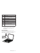
Computer Parts Listing For s30 and s31 a c b d Note: Each FRU is available for all types or models, unless specific types or models are given.
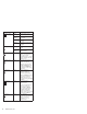
Index Description FRU Number 3 KEYBOARD ASM 02K5916 KEYBOARD ASM (i-Series) 02K5923 KEYBOARD ASM US for s31 02K5917 KEYBOARD ASM Traditional Chinese for s31 02K6170 KEYBOARD ASM Korean for s31 02K6172 HARD DISK DRIVE ASM 20 GB for s30 (includes HDD bracket, see MISC PARTS - b) 08K9612 HARD DISK DRIVE ASM 15 GB for s31 (includes HDD bracket, see MISC PARTS - b) 08K9691 HARD DISK DRIVE ASM 30 GB for s31 (includes HDD bracket, see MISC PARTS - b) 08K9689 MODEM CARD ASM for s30 08K3137 4
Description FRU Number 9-CELL BATTERY for s30 02K6802 9-CELL BATTERY for s31 02K6893 POWER CORD (Japan 2 PIN) 13H5273 CABLE PACK (RJ-11 cable, suspend board cable) 27L0643 COMBO CABLE PACK (IEEE 1394 cable, card-to-system board cable) 27L0661 MISC PARTS 26P9299 (a) UPPER COVER (b) HDD BRACKET (c) HDD/FPC BRACKET for s31 (d) PCMCIA DUMMY (e) ANTENNA HOLDER - R (s30 only) (f) FPC HOLDER (upper) (g) FPC HOLDER (lower) (h) ANTENNA HOLDER - L (s30 only) SCREW SHEET (LCD) INSULATION SHEET THERMAL PA
LCD Unit Parts Listing e f g h Index Computer FRU Number e—h See MISC PARTS list 26P9299 1 LCD BEZEL ASM 26P9303 LCD BEZEL ASM (i-Series) 26P9509 2 HINGE-R w/o antenna ASM 26P9308 3 HINGE-R w/ antenna ASM (s30 only) 26P9306 4 LCD UNIT-TFT 10.
Service Tools Description FRU No.
Notices References in this publication to IBM products, programs, or services do not imply that IBM intends to make these available in all countries in which IBM operates. Any reference to an IBM product, program, or service is not intended to state or imply that only IBM product, program, or service may be used.