2210 Nways Multiprotocol Router Service and Maintenance Guide SY27-0345-06
IBM 2210 Nways Multiprotocol Router Service and Maintenance Guide SY27-0345-06
Note Before using this information and the product it supports, be sure to read the general information under Appendix D, “Notices” on page D-1 and “Electronic Emission Notices” on page D-1. Seventh Edition (November 1998) This edition applies to the IBM 2210 Nways Multiprotocol Router. Order publications through your IBM representative or the IBM branch office serving your locality. Publications are not stocked at the address given below.
Contents About This Manual . . . . . . . . . Who Should Read This Manual . . Library Description . . . . . . . . Library Ordering Information . . . Obtaining Softcopy Information . System Library Subscription Service Visit Our Web Site . . . . . . . . . . Summary of Changes . . . . . . . . . . . . . . . . . . . . . . . . . . . . . . . . . . . . . . . . . . . . . . . . . . . . . . . . . . . . . . . . . . . . . . . . . . . . . . . . . . . . . . . . . . . . . . . . . . . . . . . . . . . . . . . . . . . . . .
UL Notices Trademarks . . . . . . . . . . . . . . . . . . . . . . . . . . . . . . . . . . . . . . . . . . . . . . . . . . . . . . . . . . . . . . . . . . . . . . . . . . . . . D-13 D-13 Glossary . . . . . . . . . . . . . . . . . . . . . . . . . . . . . . . . . . . . . . . X-1 . . . . . . . . . . . . . . . . . . . . . . . . . . . . . . . . . . . . . . . . . .
Figures 0-1. 1-1. 1-2. 1-3. 1-4. 1-5. 1-6. 1-7. 1-8. 1-9. 1-10. 1-11. 1-12. 1-13. 1-14. 1-15. 1-16. 1-17. 1-18. 4-1. 4-2. 4-3. 4-4. 4-5. 4-6. 4-7. 4-8. 4-9. 4-10. 4-11. 4-12. 4-13. 4-14. 4-15. 4-16. 4-17. 4-18. 4-19. 4-20. 4-21. 4-22. 4-23. 4-24. 4-25. 4-26. 4-27. 4-28. 4-29. 4-30. 4-31. Copyright IBM Corp. 1994, 1998 IBM 2210 Nways Multiprotocol Router Library Overview . . . . . . . Models 1Sx and 1Ux . . . . . . . . . . . . . . . . . . . . . . . . . . . Model 12T . . . . . . . . . . . . . . . . . . . .
4-32. 4-33. 4-34. 4-35. 4-36. 4-37. 4-38. 4-39. 4-40. 4-41. 4-42. 4-43. A-1. A-2. | | | | | | A-3. A-4. A-5. vi 2210 Service and Maintenance Replacing the Fan . . . . . . . . . . . . . . . . . . . . . . . . . . . . . Removing the LED Panel (12x Models) . . . . . . . . . . . . . . . . . Replacing the LED Panel (12x Models) . . . . . . . . . . . . . . . . . Removing the LED Panel (14T and 24x Models) . . . . . . . . . . . Replacing the LED Panel (14T and 24x Models) . . . . . . . . . . .
About This Manual This manual provides service information for the IBM 2210 Nways Multiprotocol Router (hereafter referred to as the IBM 2210). Who Should Read This Manual The intended user of this book is the person responsible for servicing the IBM 2210. Copyright IBM Corp.
Figure 0-1.
Library Description Introduction and Planning GA27-4068 IBM 2210 Nways Multiprotocol Router Introduction and Planning Guide This book is shipped with the 2210. It explains how to prepare for your network and for installation. This book provides translations of danger notices and other safety information.
| | vation, WAN restoral, WAN reroute, DIALs, and Network Address Translation (NAT).
Configuration Online help The help panels for the Configuration Program assist the user in understanding the program functions, panels, configuration parameters, and navigation keys. GC30-3830 Configuration Program User’s Guide for Multiprotocol Routing Services This book discusses how to use the Configuration Program. GG24-4446 IBM 2210 Nways Multiprotocol Router Description and Configuration Scenarios This book contains examples of how to configure protocols using IBM Multiprotocol Routing Services.
Obtaining Softcopy Information Softcopy BookManager READ library information is available for many of the 2210 publications in the IBM Networking Systems Softcopy Collection Kit. To place a single order for the CD-ROM, use form number SK2T-6012. Yearly subscriptions to the IBM Networking Systems Softcopy Collection Kit, product number 5636-PUB, are available through your branch office representative. Order feature code 2003 and media code 5003 for CD-ROM format.
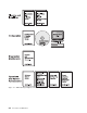
Chapter 1. Models, Indicators, and FRUs Use the illustrations in this chapter for reference when: Diagnosing problems with the IBM 2210 Repairing the IBM 2210 Models of the IBM 2210 The ports of the different models of the IBM 2210 are shown below. The 12x models shown in each illustration differ only in the amount of DRAM and flash memory they contain. Service WAN Ethernet ISDN-BRI 100-240VAC 10 0.25-0.15A 50/60Hz Figure 1-1. Models 1Sx and 1Ux Token-Ring Service Port WANs UTP STP Figure 1-2.
Token-Ring Service Port WANs UTP STP ISDN-BRI Figure 1-4. Model 127 Ethernet Service Port WANs 10 BASE-T AUI ISDN-BRI Figure 1-5. Model 128 Secondary Service Port WANs Token-Ring UTP STP Module Slot WANs Primary Service Port Figure 1-6. Model 14T Secondary Service Port WANs Primary Service Port Figure 1-7.
Secondary Service Port Ethernet WANs 10 BASE-T Ethernet AUI WANs 10 Base-T AUI Module Slot Primary Service Port Figure 1-8. Model 24E Figure 1-9. Model 24M Second Service Port WANs Primary Service Port Port LEDs Ethernet 10 BASE-T AUI WANs Adapter Slot Token-Ring UTP STP Adapter Power OK Figure 1-10. Model 24M with an Optional Adapter Installed Chapter 1.
Figure 1-11. Model 24M with the 4-port Dial Access Modem Card Installed Indicators on the IBM 2210 The IBM 2210 has green and amber light-emitting diodes (LEDs) that indicate the status of the system and of individual ports. Green indicates normal operation. Amber indicates the presence of a problem. The indicators appear on the side of the IBM 2210 containing the ports and are duplicated on the side that is opposite the ports. This arrangement allows the customer to use either side as the “front.
Reset Button The reset button, shown in Figure 1-14, works in this fashion: If you press it, you will reload the operational code. If you press it within 10 seconds of powering on, you will start the Extended POST. See “Extended POST” on page 3-1 for more information. Figure 1-14. Reset Button The reset button is recessed to prevent accidental activation. Use a pen or pencil to press it. Inside Views FRUs in the IBM 2210 12x Models Figure 1-15. View without Cover (12x Models) Chapter 1.
FRUs in the IBM 2210 x4x Models Fan Power Supply Modem or Sevice Port Card LED Panel DRAM SIMM Flash SIMM System Board Figure 1-16. View without Cover (24x Models) Cables in the IBM 2210 12x Models Figure 1-17.
Cables in the IBM 2210 x4x Models Power Supply Cable Fan Cable Reset Cable LED Panel Cable AC Power Ground AC Power Cable Figure 1-18. View of Cable Connections (24x Models) Chapter 1.
1-8 2210 Service and Maintenance
Chapter 2. Problem Determination Use the maintenance analysis procedures (MAPs) in this chapter when the IBM 2210 is not operating normally. Before using the MAPs, read these notes: Review the diagnostic instructions in Chapter 3, “Diagnostics” on page 3-1. When a MAP instructs you to replace a field-replaceable unit (FRU), see Chapter 4, “Removal and Replacement Procedures” on page 4-1.
MAP 0100: Start 001 – Gather problem determination information from the customer. – Find the symptom in Table 2-1 and take the appropriate action. Table 2-1. Initial Symptoms Symptom Action All LEDs stay on. Replace the system board. An amber LED is on or blinking. Go to “MAP 0120: LEDs Indicate a Fault” on page 2-4 No LEDs on one or both sides of the IBM 2210 are on. Go to “MAP 0130: No LEDs Are On” on page 2-8 One LED is not working.
MAP 0110: Communication Problem 001 – Make sure that: The fan is clear of any obstructions. The room temperature is within limits (5° to 41°C [50° to 104°F]) Did you find a problem? Yes No 002 Continue with Step 004. 003 Resolve the problem. Then, go to “MAP 0210: Verify Operation” on page 2-23. 004 Is the fan running? Yes No 005 Replace the fan. Then, go to “MAP 0210: Verify Operation” on page 2-23. 006 – Run the System Extended Diagnostics. For assistance, go to “Operational Diagnostics” on page 3-2.
MAP 0120: LEDs Indicate a Fault Diagnose a problem reported by the LEDs in the following sequence: 1. Use Table 2-2 to diagnose the error conditions reported by the system LEDs, because these take precedence over the port LEDs. (For example, if the system amber LED is on, it does not matter which port LEDs are on.) Note: Throughout this manual, the term system LEDs refers to the green (OK) and amber LEDs on the left side of the IBM 2210. This table is valid after power-on or Extended POST completes. 2.
006 – Go to Step 012. 007 Run an external wrap test on the port. For assistance, go to “Operational Diagnostics” on page 3-2. Is the port amber LED blinking? Yes No 008 There is a problem with the software or with the network. Contact your next level of support for instructions about reviewing the system error log. 009 Were the wrap plugs installed correctly during the Extended POST? Yes No 010 Repeat the Extended POST using the wrap plugs correctly. Take any action that is indicated.
MAP 0120 (continued) 014 (continued) Was a wrap plug installed on this port before you ran Extended POST? Yes No 015 Repeat the Extended POST using a wrap plug for this port. For assistance, go to Chapter 3, “Diagnostics” on page 3-1. Is the amber LED for this port on or blinking? Yes No 016 Go to Step 023. 017 Replace the system board. Then, go to “MAP 0210: Verify Operation” on page 2-23. 018 Replace the system board. Then, go to “MAP 0210: Verify Operation” on page 2-23.
023 (continued) Find the fault condition exhibited by this IBM 2210 in Table 2-2 on page 2-4. Perform the action indicated. Then, go to “MAP 0210: Verify Operation” on page 2-23. Chapter 2.
MAP 0130: No LEDs Are On 001 Are the LEDs on the opposite side of the unit on? Yes No 002 Go to Step 008. 003 Are the LEDs on the port side on? Yes No 004 Replace the system board. Then, go to “MAP 0210: Verify Operation” on page 2-23. 005 Remove the cover using the instructions in “Removing the Cover” on page 4-2. Is the cable connecting the system board to the LED panel securely seated? Yes No 006 Seat the cable. Go to “MAP 0210: Verify Operation” on page 2-23. 007 Replace the LED panel.
009 (continued) Did you find a problem? Yes No 010 Replace the power supply. Then, go to “MAP 0210: Verify Operation” on page 2-23. 011 Correct the problem, then, go to “MAP 0210: Verify Operation” on page 2-23. 012 Replace the system board. Then, go to “MAP 0210: Verify Operation” on page 2-23. Chapter 2.
MAP 0140: One LED is Not Working 001 – Stop the IBM 2210 by unplugging the power cord from the power outlet. – Plug the IBM 2210 power cord back into the power outlet. All LEDs should be on for 0.5 seconds after power-on. Were all the LEDs on? Yes No 002 Is the defective LED on the port side of the IBM 2210? Yes No 003 Is the cable connecting the system board to the LED panel securely seated? Yes No 004 Seat the cable. Go to “MAP 0210: Verify Operation” on page 2-23. 005 Replace the LED panel.
MAP 0150: Intermittent Problem Isolation 001 – Make sure that: All cables are attached correctly. The room temperature is not outside the limits [5° to 41°C (50° to 104°F)]. Did you find a problem? Yes No 002 Continue with Step 004. 003 Resolve the problem. Then, go to “MAP 0210: Verify Operation” on page 2-23. 004 Is the fan running? Yes No 005 Are any of the LEDs on? Check the LEDs on both sides of the IBM 2210. Yes No 006 Make sure that: The IBM 2210 is plugged into the wall outlet.
MAP 0150 (continued) 009 (continued) Replace the fan. Then, go to “MAP 0210: Verify Operation” on page 2-23. 010 Run the System Extended Diagnostics. For assistance, go to “Operational Diagnostics” on page 3-2. Did you find a problem? Yes No 011 Contact your next level of support for instructions about reviewing the system error log. 012 Resolve the problem. Then, go to “MAP 0210: Verify Operation” on page 2-23.
MAP 0160: Service Port on 12x Model Is Not Working 001 Run the Extended POST using a wrap plug in the service port. For assistance, go to Chapter 3, “Diagnostics” on page 3-1. Is the system green LED blinking and the system amber LED on? Yes No 002 There is a problem with the attached device or its cable. 003 Replace the system board. Then, go to “MAP 0210: Verify Operation” on page 2-23. Chapter 2.
MAP 0170: Primary Service Port on 14T or 24x Model Is Not Working 001 Run the Extended POST using a wrap plug in the service port. For assistance, go to Chapter 3, “Diagnostics” on page 3-1. Is the service port amber LED on or blinking? Yes No 002 There is a problem with the attached device or its cable. 003 Replace the system board. Then, go to “MAP 0210: Verify Operation” on page 2-23.
MAP 0180: Second Service Port Is Not Working 001 Is the service port green LED on? Yes No 002 Check the connection to the system board. Is the service port seated correctly in the socket? Yes No 003 Seat the service port in the socket firmly. Is the problem corrected? Yes No 004 Go to Step 007. 005 Go to “MAP 0210: Verify Operation” on page 2-23. 006 Go to Step 007. 007 Run the Extended POST using a wrap plug in the service port. For assistance, go to Chapter 3, “Diagnostics” on page 3-1.
MAP 0180 (continued) 010 (continued) Is the service port amber LED blinking? Yes No 011 Is the service port amber LED on? Yes No 012 Make sure the service port is seated correctly. Is the service port seated correctly? Yes No 013 Seat the service port correctly and then go to Step 007 on page 2-15. 014 Go to Step 016. 015 Replace the system board. Then, go to “MAP 0210: Verify Operation” on page 2-23. 016 Replace the service port. Then, go to “MAP 0210: Verify Operation” on page 2-23.
MAP 0190: Service Terminal Display Unreadable Symptom Explanation Conditions That Could Cause This Symptom While you are diagnosing a problem, a terminal attached to the service port of the 2210 displays random characters instead of readable text. Incorrect configuration setting of the terminal or 2210 service port. Incorrect terminal/device (ac) grounds. Defective, incorrectly shielded, or incorrectly grounded RS EIA 232 cable between the terminal and the 2210.
MAP 0190 (continued) 006 (continued) – Press Ctrl-c at the service terminal. The 2210 autobauds to the terminal speed. The > prompt should be displayed at this time. The terminal speed is not saved and the next time the 2210 is reset or powered off, the service port will use the old speed. – Continue at Step 001 on page 2-17 when you have resolved the boot problem. 007 – Press the service terminal break key sequence and press Enter. You should try this a number of times before proceeding.
012 (continued) – Set the terminal to the configured console baud rate displayed. – Press the service terminal break key sequence and press Enter. This action causes the 2210 to auto-baud. – Enter Ctrl-c. The > prompt should be displayed. If the console baud rate is satisfactory, you can reboot the 2210 and the terminal will work. If the console baud rate is unsatisfactory and you want to change the rate: 1. Enter bc at the > prompt and select an IBD boot module. 2.
MAP 0190 (continued) 018 (continued) Is the RS 232 cable between the terminal and the IBM 2210 grounded correctly and shielded? Yes No 019 Ground or shield the cable correctly or replace the cable. Go to “MAP 0210: Verify Operation” on page 2-23. 020 Is the terminal or the terminal emulator functioning correctly? Yes No 021 Replace the terminal or the terminal emulator. Go to “MAP 0210: Verify Operation” on page 2-23.
MAP 0200: Optional Adapter or Dial Access Adapter Is Not Working Note: See Figure 1-10 on page 1-3 or Figure 1-11 on page 1-4 for position of adapter status LED. 001 Is the adapter green status LED on? Yes No 002 Is the adapter firmly seated in the riser? Yes No 003 Seat the adapter firmly in the riser, then go to Step 001.
MAP 0200 (continued) 009 (continued) Is this the Dial Access Adapter? Yes No 010 Replace the adapter, then go to “MAP 0210: Verify Operation” on page 2-23. 011 Is the amber status LED on or blinking? Yes No 012 Replace the adapter, then go to “MAP 0210: Verify Operation” on page 2-23. Note: The Dial Access Adapter feature has two 4-port Dial Access Modem Cards and a Dial Access Base Adapter. Any of these cards could be failing. Replace the cards one at a time and retry.
MAP 0210: Verify Operation 001 Reinstall the covers of the IBM 2210. Is an ASCII terminal attached to the IBM 2210? Yes No 002 Run the Extended POST. For assistance, go to Chapter 3, “Diagnostics” on page 3-1. Is any amber LED on or blinking? Yes No 003 Go to Step 007. 004 Go to “MAP 0120: LEDs Indicate a Fault” on page 2-4. 005 Run the System Extended Diagnostics. For assistance, go to “Operational Diagnostics” on page 3-2.
2-24 2210 Service and Maintenance
Chapter 3. Diagnostics The IBM 2210 diagnostic programs test the system hardware and detect hardware problems. The diagnostic routines include three types of tests: Power-on self-test (POST) Extended POST Menu-driven diagnostics The diagnostic package includes service aids that may be used to display the diagnostic logs and to view the vital product data (VPD).
4 If the Extended POST has completed successfully: The green LEDs for the system (OK) and for any port with wrap plugs will be on. The port amber LEDs will be off (or blinking if no wrap plug is installed). For the 12x models, the system (OK) green LED blinking with the system amber LED on indicates that the service port external wrap test has failed. 5 To run the extended POST again, press the reset button after 2 minutes.
3 The greater-than sign (>) will appear on the display. 4 Type diag and press Enter. 5 The Diagnostic Main Menu will appear after the System Diagnostics run. While the Router User Interface Is In Operation: To start the diagnostics while the router user interface is in operation: 1 Press Ctnl-p. An asterisk (\) will appear. 2 Type reload and press Enter. 3 Press Ctnl-c. The greater-than sign (>) will appear on the display. 4 Type diag and press Enter. 5 The Diagnostic Main Menu will appear.
Possible symptoms of a software problem: A component stops operating and hardware diagnostics do not identify a hardware problem System stalls A severe drop occurs in system performance Data is incorrectly transmitted A system does not receive data that was correctly transmitted Service Aids Service aids are utility programs that provide additional diagnostic assistance. The service aids for the IBM 2210 are for use under the direction of support personnel.
Chapter 4. Removal and Replacement Procedures Note: Before installing the IBM 2210, be sure to read “Electronic Emission Notices” on page D-1.
DANGER An electrical outlet that is not correctly wired could place hazardous voltage on metal parts of the IBM 2210 or the devices that attach to the IBM 2210. It is the responsibility of the customer to ensure that the outlet is correctly wired and grounded to prevent an electrical shock. Before installing or removing signal cables, ensure that the power cord for the IBM 2210 is unplugged.
2 If the IBM 2210 is installed in a rack, remove the screws attaching the IBM 2210 to the rack. 3 Remove the two screws that attach the mounting brackets to either side of the IBM 2210. Then remove the center screw that attaches the cover to the side of the IBM 2210. Note the position of the mounting bracket ears as you remove the mounting brackets. Figure 4-1. Removing the Side Screws 4 Position the IBM 2210 so that the port side is facing you.
Reinstalling the Cover 1 Position the IBM 2210 so that the port side is facing you. From this position, elevate the rear portion of the cover and slide it onto the IBM 2210. Figure 4-3. Replacing the Cover 2 Replace the screws that attach the cover and mounting brackets to each side of the machine. Be sure that the screw with the Phillips head is installed in the middle hole. Figure 4-4. Replacing the Screws and Mounting Bracket 3 If the IBM 2210 was mounted in a rack, return it to the rack.
System Board Refer to “Handling Static-Sensitive Devices” on page 4-2 before removing or installing a system board. Removing the System Board for 12x Models Figure 4-5. Cables Attached to the System Board (12x Models) 1 Remove the power supply cable connector by pulling out the retaining clips with your fingers or a screwdriver and then rocking the connector from front to back as you pull up. 2 Remove the fan cable by rocking it from front to back as you pull up.
Figure 4-6. Non-ISDN System Board (12x Models) Figure 4-7. ISDN System Board 5 Using a nut driver, remove the hex screws from the service port and from the token-ring port, if present on this IBM 2210. 6 If you have an Ethernet port, remove both screws from the bracket on the port, noting the position of the bracket as you remove it.
Figure 4-8. Ethernet Port (12x Models) 7 With a screwdriver, remove the remaining slotted screws that attach the WAN ports to the front panel. 8 You will transfer the single in-line memory module (SIMM) from this system board to the new one. Go to “Removing the Dynamic Random Access Memory (DRAM) SIMM for 12x Models” on page 4-15 for instructions for removal. After you remove the SIMM, lift the system board out of the unit.
Figure 4-10. ISDN System Board (12x Models) 4 Using a nut driver, replace the hex screws in the service port and in the token-ring port, if present on this IBM 2210. 5 If you have an Ethernet port, replace the bracket. See Figure 4-8 on page 4-7 for reference. 6 Replace the remaining slotted screws that attach the WAN ports to the front panel. Figure 4-11.
8 Attach the fan cable by pressing firmly down until it clicks into place. 9 Position the power supply cable connector so that the side of the connector with the tabs faces the retaining clips. Then, press firmly down until it clicks into place. 10 Reinstall the cover. See “Reinstalling the Cover” on page 4-4 for instructions. Note: The customer must reload operational code and configuration information after the system board is replaced.
Power Supply Cable Fan Cable Reset Cable LED Panel Cable AC Power Ground AC Power Cable Figure 4-13. Cables Attached to the System Board - 24x Models 1 Remove any optional adapters, if installed. See “Removing the Optional Adapter” on page 4-38 for the removal procedure. 2 Remove the power supply cable connector by pulling out the retaining clips with your fingers or a screwdriver and then rocking it from front to back as you pull up.
Figure 4-14. Retainer Screws on 14T and 24X Models 9 Using a nut driver, remove the hex screws from the service port and from the token-ring ports, if present on this IBM 2210. 10 Remove both screws from the bracket on the Ethernet ports, if present on this IBM 2210, noting the position of the bracket as you remove it. Chapter 4.
Figure 4-15. Ethernet Port 11 Using a screwdriver, remove the remaining slotted screws that attach the WAN ports to the front panel. 12 You will transfer memory modules from this system board to the new one. Go to “Removing the Dynamic Random Access Memory (DRAM) SIMM for 12x Models” on page 4-15 and “Removing the Flash and DRAM SIMMs in Model 14T and 24x” on page 4-17 for instructions for removal. After you remove the memory, lift the system board out of the unit.
Figure 4-16. System Board Retainer Screws (14T and 24x Models) 4 Using a nut driver, replace the hex screws in the service port and in the token-ring port, if present on this IBM 2210. 5 Replace the bracket on the Ethernet port, if present. See Figure 4-8 on page 4-7 for reference. 6 Replace the remaining slotted screws that attach the WAN ports to the front panel. Chapter 4.
Power Supply Cable Fan Cable Reset Cable LED Panel Cable AC Power Ground AC Power Cable Figure 4-17. Attach Cables to the System Board - 14T Models Power Supply Cable Fan Cable Reset Cable LED Panel Cable AC Power Ground AC Power Cable Figure 4-18. Attach Cables to the System Board - 24x Models 7 To attach the LED panel cable, slide the cable into the connector making sure that the blue coloring on the end of the cable faces the blue latch. Be sure to slide the cable into the latch as far as possible.
10 Attach the fan cable by pressing firmly down until it clicks into place. 11 Position the power supply cable connector so that the side of the connector with the tabs faces the retaining clips. Then, press firmly down until it clicks into place. 12 Reinstall the cover. See “Reinstalling the Cover” on page 4-4 for instructions. Note: The customer must reload operational code and configuration information after the system board is replaced.
1 Push back the retaining tabs located at each end of the SIMM socket. The SIMM will fall forward. 2 Remove the SIMM by gently pulling it toward you. Replacing the DRAM SIMM for 12x Models Figure 4-20. Replacing the DRAM SIMM in 12x Models 1 Tilt the top of the SIMM toward you and slide it into the retainer. 2 Press the SIMM backward until the retaining tabs are holding it securely.
Removing the Flash and DRAM SIMMs in Model 14T and 24x Figure 4-21. Removing the Flash SIMM (14T and 24x Models) 1 Remove the cover from the IBM 2210 as described in “Removing the Cover” on page 4-2. 2 Push back the retaining tabs located at each end of the SIMM socket. The SIMM will fall backwards. 3 Remove the SIMM by gently pulling it away from you. 4 Replace the cover on the IBM 2210 as described in “Reinstalling the Cover” on page 4-4.
Installing the Flash and DRAM SIMMs in Models 14T and 24x | | Note: When using 32 MB of memory with a 14T or 24x model you must be at revision level 2.34 or higher of the PROM Load/Dump Program. Refer to “Handling Static-Sensitive Devices” on page 4-2 before removing or installing a flash SIMM. Figure 4-22. Installing the Flash SIMM (14T and 24x Models) 1 Remove the cover from the IBM 2210 as described in “Removing the Cover” on page 4-2.
Power Supply Removing the Power Supply for 12x Models Figure 4-23. Connections to the Power Supply (12x Models) 1 Remove the connector to the system board (A) by pulling out the retaining clips with your fingers or a screwdriver and then rocking the connector from front to back as you pull up. 2 Remove the connector to the ac power source (B). 3 Remove the spade lug terminal ground for the ac power source (C), using needle-nose pliers. Chapter 4.
Figure 4-24. Removing the Screws from the Power Supply (12x Models) 4 Remove the four corner hex screws from the power supply. 5 Lift the power supply out of the system unit. Be sure to leave the insulator in place when you remove the power supply and note the position of the regulator protection tab.
Replacing the Power Supply for 12x Models Figure 4-25. Replacing the Corner Screws (12x Models) 1 Place the power supply on top of the insulator, being sure the regulator protection tab is perpendicular to the base of the unit. Replace the four hex screws. Chapter 4.
Figure 4-26. Connections to the Power Supply (12x Models) 2 Replace the spade lug terminal ground (A). 3 Replace the connector to the ac power source (B). 4 Position the connector to the system board (C) so that the side of the connector with the tabs faces the retaining clips. Then, press firmly down until it clicks into place. Be sure it is firmly seated.
Figure 4-27. Removing the Screws from the Power Supply (14T and 24x Models) 2 Remove the connector to the system board by pulling out the retaining clips with your fingers or a screwdriver and then rocking it from front to back as you pull up. Chapter 4.
Power Supply Cable Fan Cable Reset Cable LED Panel Cable AC Power Ground AC Power Cable Figure 4-28. Connections to the Power Supply (14T and 24x Models) 3 If the Adapter Enablement Feature feature is installed, remove the connector to the adapter riser card. 4 Remove the power supply cover by sliding the cover toward the fan until the leading edge of the cover clears the front panel, then lifting. 5 Remove the connector from the adapter power supply, if installed, to the ac power source.
Replacing the Power Supply for 14T and 24x Models 1 Place the power supply on top of the insulator, being sure the regulator protection tab is perpendicular to the base of the unit. Replace the four hex screws. Power Supply Cable Fan Cable Reset Cable LED Panel Cable AC Power Ground AC Power Cable Figure 4-29. Connections to the Power Supply (14T and 24x Models) 2 Replace the connector to the ac power source. 3 Replace the connector from the adapter power supply, if installed, to the ac power source.
Figure 4-30. Replacing the Power Supply Cover 4 Replace the power supply cover over the power supply by sliding the cover forward until the leading edge is beneath the front panel. Make sure that the reset card cable is beneath the cover and not between the cover and the front panel.
Also make sure that the connectors feed through the space between the side and rear of the cover and the connectors without the jumpers are connected to the power supplies. 5 Replace the screws that attach the power supply cover to the chassis as shown in Figure 4-30 on page 4-26. 6 If the Adapter Enablement Feature is installed, position the connector to the adapter riser card so that the side of the connector with the tabs faces the retaining clips. Then, press firmly down until it clicks into place.
1 Remove the connector to the system board by rocking it from front to back as you pull up. 2 Remove the screws from the mounting bracket that encases the fan on the 12x models. On the 14T and 24x models, remove the screws that attach the fan to the rear of the IBM 2210 chassis. 3 Lift the fan from the system unit. Replacing the Fan Figure 4-32.
LED Panel Removing the LED Panel for 12x Models Figure 4-33. Removing the LED Panel (12x Models) 1 To remove the LED panel cable, use a screwdriver on either side of the connector to lift the blue retaining latch. Pull the cable from the latch. Note as you remove this cable that the blue coloring on the end of the cable faces the blue latch. 2 Remove the two screws that attach the LED panel to the floor of the machine.
Replacing the LED Panel for 12X Models Figure 4-34. Replacing the LED Panel (12x Models) 1 Slide the LED panel into place, making sure the LED bulbs fit into the openings on the wall of the machine. 2 Replace the two screws that attach the LED panel to the floor of the machine. 3 Attach the LED panel cable by sliding the cable into the connector, making sure that the blue coloring on the end of the cable faces the blue latch. Be sure to slide the cable into the latch as far as possible.
Removing the LED Panel for 14T and 24x Models Figure 4-35. Removing the LED Panel (14T and 24x Models) 1 To remove the LED panel cable, use a screwdriver on either side of the connector to lift the blue retaining latch. Pull the cable from the latch. Note as you remove this cable that the blue coloring on the end of the cable faces the blue latch. 2 Remove the four screws that attach the LED panel to the floor of the machine.
Replacing the LED Panel for 14T and 24X Models Figure 4-36. Replacing the LED Panel (14T and 24x Models) 1 Slide the LED panel into place, making sure the LED bulbs fit into the openings on the wall of the machine. 2 Replace the four screws that attach the LED panel to the floor of the machine. 3 Attach the LED panel cable by sliding the cable into the connector, making sure that the blue coloring on the end of the cable faces the blue latch. Be sure to slide the cable into the latch as far as possible.
| | | | | to delete any virtual interfaces, for example, dial circuits, associated with the adapter prior to removing the adapter. The talk 6 delete interface command deletes the interface you explicitly state in the command line. The interface in current use will not be deleted unless you specify that interface name in the command line. If the guide rails are visible, the feature is installed and you can continue the installation at “Installing Optional Adapters” on page 4-36.
Figure 4-37. Assembling the Riser Card 1 Attach the riser card Assembly with the supplied screw to the riser brace as shown in Figure 4-37. 2 Attach the left guide assembly to the riser brace. 3 Attach the right guide assembly to the riser brace. Note: Position the guide assemblies as far from each other as possible before tightening screws.
Installing the Adapter Enablement Feature Figure 4-38. Installing the Adapter Enablement Feature 1 Carefully place the assembly in position and plug the riser card assembly into the socket on the system board. 2 Fasten the rear of the assembly to the system board using the supplied screw. Chapter 4.
3 Fasten the front of the assembly to the front frame using the supplied screws. 4 Insert an optional adapter into the module slot to ensure the adapter fits into the assembly correctly. 5 Tighten all screws on the assembly. 6 Attach the dc power cable to the connector on the left-hand side of the riser card assembly. Make sure the connector with the jumper is connected to the riser card. 7 Connect the jumpers between the base power supply and the adapter power supply together.
Figure 4-39. Installing the Optional Adapter (Actual adapter may appear different) 1 Unplug the power cord. 2 Remove the blank faceplate by loosening the two screws and pulling the plate toward you. 3 Check to ensure that the Adapter Enablement Feature is installed. Look inside the module slot and ensure that the guide rails for the card are present. If the guide rails are not visible, an authorized service representative must install the Adapter Enablement Feature.
9 Verify that the IBM 2210 is functioning correctly by using “MAP 0210: Verify Operation” on page 2-23. Removing the Optional Adapter Figure 4-40. Removing the Adapter (Actual adapter may appear different) 1 Unplug the power cord. 2 Remove the screws holding the adapter in place. 3 Remove the adapter by gently pulling it toward you. 4 Replace the blank faceplate or install new adapter and tighten the two screws. 5 Plug the power cord into the outlet.
Installing a Second Service Port in Models 14T and 24x Refer to “Handling Static-Sensitive Devices” on page 4-2 before removing or installing a second service port card. Installing the EIA 232 Service Port Feature in Models 14T and 24x Figure 4-41. Installing the EIA 232 Service Port Feature 1 Remove the cover from the IBM 2210 as described in “Cover” on page 4-2. 2 Remove the blank Service Port faceplate by unscrewing the two screws. 3 Save the faceplate and screws.
8 Verify that the IBM 2210 is functioning correctly by using “MAP 0210: Verify Operation” on page 2-23. Removing the EIA 232 Service Port Feature in Models 14T and 24x 1 Remove the cover from the IBM 2210 as described in “Cover” on page 4-2. 2 Remove the two screws that secure the EIA 232 Service Port Feature to the IBM 2210 frame. 3 Remove the Philips-head screw that attaches the middle of the EIA 232 Service Port Feature to the standoff on the system board.
5 Attach the 14.4 Kbps Modem Port Feature to the system board by inserting the alignment post through the top of the modem and screwing in the post. 6 Using the two screws from the blank faceplate secure the front of the Modem Card faceplate to the frame of the 2210. 7 Replace the cover as described in “Reinstalling the Cover” on page 4-4. 8 Verify the IBM 2210 is functioning correctly by using “MAP 0210: Verify Operation” on page 2-23. Removing the 14.
Upgrading the 4-Port Dial Access Adapter Using the 4-Port Dial Access Modem Card Feature Note: This procedure assumes that you have a 4-port Dial Access Adapter installed in your IBM 2210. Rear Blanking Plate CD OH Re ad 1 y 2 3 4 4 Port Connector Plug 5 6 7 Front Blanking Plate 8 Po w Fa er ult Blanking Plate Screws Figure 4-43. Upgrading the 4-Port Dial Access Adapter To upgrade the 4-port Dial Access Adapter with a new 4-port Dial Access Modem Card: 1.
10. Store the antistatic bag in a safe place. You will need this if you remove the adapter from the IBM 2210. Removing the 4-Port Dial Access Modem Card To remove the 4-port Dial Access Modem Card from the Dial Access Adapter: 1. Remove the adapter from the IBM 2210 as described in “Removing the Optional Adapter” on page 4-38. 2. Using a nut driver, remove the three screws securing the 4-port Dial Access Modem Card. 3.
4-44 2210 Service and Maintenance
Appendix A. Access Methods and Attaching an ASCII Terminal | | | | To run the menu-driven diagnostics, you must attach an ASCII terminal to the service port of the IBM 2210. This chapter explains how to access the IBM 2210’s operational and configuration software. The chapter also lists the ASCII terminals that are supported and provides information about setup attributes. Access Methods | | The IBM 2210 software must be configured as part of the installation process.
| Figure A-2. Remote Connection to 14.4 Kbps Modem Port Feature (14T and 24x Models) | | Figure A-3. Remote Terminal Connection to the Primary or Secondary EIA-232 Service Port | | Service Port Default Settings These are the default settings for the serial port: | | | | Speed Parity Data Bits Stop Bits | | | You can configure the service port speed for the following bit rates; however, the speed must match the speed configured for the ASCII terminal. The IBM 2210 also supports auto-baud.
| | | Hardware (RTS/CTS) flow control Modem DTE speed fixed to match 2210 service port speed (9600 recommended). | Consult your modem documentation on how to configure and save these settings. | | | | | | | Remote Connection for Service To resolve a problem with your IBM 2210, IBM service personnel may request permission to establish a temporary, remote connection to the IBM 2210. In most situations, the IBM service personnel will not be at a remote workstation that is connected to your IP network.
10 0.40-24 -0 0V .2A AC 50 10 /60 Hz | Figure A-4. Attaching an ASCII Terminal to the Service Port | | | | | | | | When locally attaching a terminal to the IBM 2210 service port, the speed (baud rate) configured for the service port must match the speed of the connected terminal if the IBM 2210 has been configured to use a specific baud rate.
| 300 bps–38.4 Kbps bit rate The terminal speed must match the serial port speed. The following terminals are also supported: IBM 3101 Display Terminal IBM 3151 ASCII Display Station IBM 3161 ASCII Display Station Configure these terminals as shown in “Setup Attributes.” Setup Attributes IBM 3101 Setup Attributes Use Figure A-5 to determine the settings for the setup attributes for the IBM 3101 ASCII terminal. Figure A-5.
Table A-2. Setup Attributes for the IBM 3151 Attribute Setting Machine Mode Scroll Auto LF Line Wrap Operating Mode Word Length (bits) Stop Bit Turnaround Character Line Control Break Signal (ms) Send Null Suppress 3151 JUMP OFF OFF ECHO 8 1 CR IPRTS 500 ON Supported bit rates (in bps) are: | 1200 2400 4800 9600 19 200 38 400 The terminal speed must match the serial port speed. IBM 3161 Setup Attributes Activate setup mode in the IBM 3161 terminal by pressing the Ctrl and Setup keys.
| The terminal speed must match the serial port speed. You now need to set up additional attributes for the 3161. To set up the additional attributes: 1. Press Select to display the attribute selection bar. 2. Change the values on the selection bar to match the values in Table A-4. To move between selections while on a selection bar, press Tab. To change a value for an attribute, press the spacebar. 3. Press Send to accept the current values for the attributes on the selection bar. 4.
| | | | EasyStart mode automatically downloads the configuration of the router from a BOOTP server. During the process, the router displays the EasyStart> prompt and ELS messages that track the process. See the Software User’s Guide for Multiprotocol Routing Services for more information about EasyStart. | Configuration Program | | | | | | | | | The Configuration Program allows you to configure the IBM 2210 completely once Quick Configuration has taken place.
Appendix B. Service Kit This appendix identifies by part number the items contained in the service kit for the IBM 2210. The service kit, PN 04H8169, is stocked as a branch office tool. Service personnel should obtain a kit for their use when servicing this machine. Table B-1. Parts in Service Kit Part Part Number ATM 25MB wrap plug 42H0540 EIA 232-D/V.24 modem-attach wrap plug 60G3909 EIA 232-D/V.
B-2 2210 Service and Maintenance
Appendix C. Parts Listing This parts listing contains reference drawings and a corresponding index for all field replaceable parts. The index provides the part number, the quantity required (units), and a description of the part. Listed below is additional information about the parts assembly index. SIMILAR ASSEMBLIES: If two assemblies contain a majority of identical parts, they are broken down on the same list. Common parts are shown by one index number.
Assembly 1: Final Assembly – 12x Models 1 22 23 21 22 2 24 4 3 18 20 19 17 5 11 6 16 15 15B 15A 9 10 12 13 14 8 C-2 2210 Service and Maintenance AMF0P001 7
Asm– Index 1–1 –1 –2 –3 –3 –3 –3 –4 –5 –6 –7 –8 –9 –9 –9 –9 –9 –9 –9 –9 –9 –9 –10 –10 –10 –10 –11 –12 –13 –14 –15 –15A –15B –16 –17 –17 –17 –17 –17 –17 –17 –17 –17 –17 –18 –19 –19 –19 Part Number 4H7060 4H8201 4H8202 4H8203 4H8204 1624743 92G8547 92G8546 4H7088 92G8549 4H8211 4H8212 4H8213 4H8213 4H8214 4H8214 4H8215 4H8216 4H8217 4H8218 1622346 1622318 1622403 73G3485 73G4036 73G4037 62X0388 72H3627 4H8192 72H3628 72H3628 4H8194 4H8194 4H8195 4H8196 4H8197 4H8198 1624743 4H8189 4H8190 41H7107 Units NP
Assembly 1: (continued) 1 22 23 21 22 2 24 4 3 18 20 19 17 5 11 6 16 15 15B 15A 9 10 12 13 14 8 C-4 2210 Service and Maintenance AMF0P001 7
Asm– Index 1–1 –20 –21 –22 –23 –24 –25 Part Number Units 74G0039 4H8199 1624743 72H3623 4H8200 4H8169 NP 1 1 6 1 1 1 Description Final Assembly Insulator Power Supply Asm Screw, Hex, M3 X 6 Lg Cable, DC Fan Asm Wrap Plug Service Kit (Not Illustrated) Appendix C.
Assembly 2: Final Assembly, — 14T Model 1 26 25 2 20 24 23 3 22 4 19 5 18 27 17 14 6A 16 15 6B 13 12 21 11 9 10 C-6 2210 Service and Maintenance 7 8
Asm– Index | 2–2 –1 –2 –3 –4 –5 –5 –6A –6B –7 –8 –9 –10 –11 –12 –13 –14 –15 –16 –17 –18 –19 –19 –20 –21 –22 –23 –23 –24 –25 –26 –27 –27 –27 –27 Part Number Units 13H8412 1624743 1624743 41H7108 72H5029 13H8803 13H8804 4H7088 92G8549 41H7111 73G3485 73G4036 73G3485 73G4037 41H7082 13H8805 41H7103 92G8546 41H7110 41H7104 41H7105 41H7101 92G8546 13H8807 41H7109 55H7477 1624743 13H8806 1624743 04H8189 04H8190 41H7107 55H7492 NP NP 1 4 9 1 1 1 1 2 1 1 4 1 4 4 1 NP 1 4 1 1 1 1 4 1 1 1 4 1 4 1 1 1 1 Descrip
Assembly 3: Final Assembly — 24x Models 1 28 27 2 20 26 25 3 24 4 19 5 18 29 17 14 6A 16 15 6B 13 12 21 11 10 C-8 2210 Service and Maintenance 9 8 22 23 7
Asm– Index 3–3 –1 –2 –3 –4 –5 –5 –6A –6B –7 –8 –9 –22 –23 –10 –11 –12 –13 –14 –14 –14 –15 –16 –17 –18 –19 –19 –20 –21 –24 –25 –25A –26 –27 –28 –29 –29 –29 –29 Part Number Units 13H8412 1624743 1624743 41H7108 72H5029 13H8803 13H8804 4H7088 92G8549 41H7112 41H7113 41H7114 73G3485 73G4036 73G3485 73G4037 41H7083 41H7084 41H7085 13H8805 41H7103 92G8546 41H7110 41H7104 41H7105 41H7102 92G8546 13H8807 41H7109 55H7477 1624743 13H8806 1624743 04H8189 04H8190 41H7107 55H7492 NP NP 1 4 9 1 1 1 1 2 1 1 1 1 4 1 4
Assembly 4: Final Assembly — Adapter Enablement Feature 2 8 9 7 5 1 11 10 4 6 3 12 C-10 2210 Service and Maintenance
Asm– Index | | 4–4 –1 –2 –3 –4 –5 –6 –7 –8 –9 –10 –11 –12 – – – – – – – – – – Part Number 13H8807 55H7477 1624743 41H7109 41H7119 1624769 1624743 85H7770 41H7120 55H7509 41H7106 41H9109 55H7491 85H7783 72H5063 72H5038 72H5037 Units NP 1 1 4 1 1 NP NP NP AR NP AR 1 AR AR AR AR AR AR Description Final Assembly Power Supply Insulator DC Power Supply Cable Screw, Hex, M3 X 6 Lg Power Supply Riser Card Assembly Guide Assembly, Right Guide Assembly, Left Riser Card Brace Screw, Fix
Assembly 5: Cable Assemblies Asm– Index | 5–3 –4 –5 –6 –7 –8 –9 –10 –11 –12 –13 –14 –15 –16 –17 –18 –20 C-12 Part Number Units 60G3902 60G3903 60G3904 60G3906 10H5591 1749352 6339098 10H5569 10H5570 41H9082 55H7756 60G3901 85H3509 57G8042 80G3984 85H7778 86H0774 1 1 1 1 1 1 1 1 1 1 1 1 1 1 1 1 1 2210 Service and Maintenance Description Cable, V.35 Feature Cable, V.35 (DTE) Feature Cable, V.36 CCITT Feature Cable, X.21 CCITT Feature Cable, X.21 DTE Feature Cable Adapter, V.
Appendix C.
Assembly 6: Final Assembly, IBM 2210, Models 1Sx and 1Ux Service 100-240VAC 10 0.25-0.
Asm– Index Part Number 6–6 –1 –2 –3 –4 85H7990 85H7791 85H7792 85H7793 Units 1 Description Final Assembly Model 1U4 Model 1U8 Model 1S4 Model 1S8 Appendix C.
C-16 2210 Service and Maintenance
Appendix D. Notices References in this publication to IBM products, programs, or services do not imply that IBM intends to make these available in all countries in which IBM operates. Any reference to an IBM product, program, or service is not intended to state or imply that only IBM’s product, program, or service may be used. Any functionally equivalent product, program, or service that does not infringe any of IBM’s intellectual property rights may be used instead of the IBM product, program, or service.
accordance with the instruction manual, may cause harmful interference to radio communications. Operation of this equipment in a residential area is likely to cause harmful interference, in which case the user will be required to correct the interference at his own expense. Properly shielded and grounded cables and connectors must be used in order to meet FCC emission limits.
Industry Canada Class B Emission Compliance Statement | This Class B digital apparatus complies with Canadian ICES-003. Avis de conformité aux normes d'Industrie Canada | | Cet appareil numérique de la classe B est conform à la norme NMB-003 du Canada.
Dieses Gerät ist berechtigt in Übereinstimmung mit dem deutschen EMVG vom 9.Nov.92 das EG-Konformitätszeichen zu führen. Der Außteller der Konformitätserklärung ist die IBM Spain, Division of Fabricacion, 46185 La Pobla de Vallbona, Valencia, Spain. Dieses Gerät erfüllt die Bedingungen der EN 55022 Klasse B. Notice about Lithium Battery The IBM 2210 contains a non-replaceable lithium battery that, if disposed of improperly, can cause a fire, an explosion, or a severe burn.
If trouble is experienced with this equipment, for repair or warranty information, in the United States, call IBM at 1-800-IBM-SERV. In Canada, call IBM at 1-800-465-6600. No repairs can be performed by the customer. Industry Canada Information NOTICE: The Industry Canada label identifies certified equipment. This certification means that the equipment meets certain telecommunications network protective, operational and safety requirements.
conformité de son équipement aux conditions susmentionnées n’est pas une prévention contre la dégradation du service dans certaines situations. Toute réparation d’un équipement homologué devrait être effectuée par un service de maintenance canadien autorisé qui a été désigné par le fournisseur.
Gevaar: Er bevindt zich gevaarlijke spanning binnenin deze machine, wanneer ze is ingeschakeld. Telkens als u onderhoud uitvoert op deze eenheid, met de behuizing verwijderd, moet u het netsnoer loskoppelen. Danger: Avant de procéder à l'installation de ce produit, lisez d'abord les consignes de sécurité dans la brochure ATTENTION: Consignes de sécurité—A lire au préalable, SD21-0030. Cette brochure décrit les procédures pour câbler et connecter les appareils électriques en toute sécurité.
Vorsicht: Bei eingeschaltetem Gerät liegen im Innern gefährliche Spannungen an. Sicherstellen, daß bei Arbeiten an der geöffneten Maschine der Netzstecker gezogen ist. Perigo: Antes de iniciar a instalação deste produto, leia as informações de segurança Cuidado: Informações de Segurança — Leia Primeiro, SD21-0030. Este documento descreve como efectuar, de um modo seguro, as ligações eléctricas dos equipamentos. Perigo: Este equipamento, quando ligado, apresenta tensões perigosas no seu interior.
Vaara: Virran ollessa kytkettynä koneen sisällä on vaarallisia jännitteitä. Muista aina irrottaa verkkojohto, jos huollat konetta sen suojakannen ollessa irrotettuna. Fare! Før du installerer dette produkt, skal du læse sikkerhedsforskrifterne i NB: Sikkerhedsforskrifter—Læs dette først SD21-0030. Vejledningen beskriver den fremgangsmåde, du skal bruge ved tilslutning af kabler og udstyr. Fare! Der er høj spænding i denne maskine, når den er tændt.
Perigo: Antes de começar a instalar este produto, leia as informações de segurança contidas em Cuidado: Informações Sobre Segurança—Leia Isto Primeiro, SD21-0030. Esse folheto descreve procedimentos de segurança para a instalação de cabos e conexões em equipamentos elétricos. Perigo: Existem voltagens perigosas no interior desta máquina quando ela está ligada. Toda vez que você for fazer a manutenção desta unidade com a tampa aberta, certifique-se de desconectar o cabo de força.
Danger: Tension dangereuse à l'intérieur de la machine lorsque celle-ci est sous tension. Avant toute intervention à l'intérieur, débranchez le cordon d'alimentation. Vigyázat: Mielôtt megkezdi a berendezés üzembe helyezését, olvassa el a “Caution: Safety Information— Read This First, SD21-0030 könyvecskében leírt biztonsági információkat. Ez a könyv leírja, milyen biztonsági intézkedéseket kell megtenni az elektromos berendezés huzalozásakor illetve csatlakoztatásakor. Appendix D.
D-12 2210 Service and Maintenance
UL Notices Never install telephone jacks in wet locations unless the jack is specifically designed for wet locations. Never touch uninsulated telephone wires or terminals unless the telephone line has been disconnected at the network interface. Use caution when installing or modifying telephone lines. Avoid using a telephone (other than a cordless type) during an electrical storm. There may be a remote risk of electrical shock from lightning.
D-14 2210 Service and Maintenance
Glossary This glossary includes terms and definitions from: The IBM Dictionary of Computing (New York; McGraw-Hill, Inc., 1994). The American National Standard Dictionary for Information Systems, ANSI X3.172-1990, copyright 1990 by the American National Standards Institute (ANSI). Copies may be purchased from the American National Standards Institute, 11 West 42nd Street, New York, New York 10036. Definitions are identified by the symbol (A) after the definition.
B baud. (1) A unit of signaling speed equal to the number of discrete conditions or signal events per second; for example, one baud equals one-half dot cycle per second in Morse code, one bit per second in a train of binary signals, and one 3-bit value per second in a train of signals each of which can assume one of eight different states.
dump. (1) Data that has been dumped. (T) (2) To copy the contents of all or part of virtual storage for the purpose of collecting error information. E EC. European community. EIA. Electronic Industries Association. Electronic Industries Association (EIA). An organization of electronics manufacturers that advances the technological growth of the industry, represents the views of its members, and develops industry standards. EIA 232.
Internet Protocol (IP). (1) A protocol that routes data through a network or interconnected networks. IP acts as an interface between the higher logical layers and the physical network. However, this protocol does not provide error recovery, flow control, or guarantee the reliability of the physical network. IP is a connectionless protocol. (2) A protocol used to route data from its source to its destination in an Internet environment. inverse ARP.
MTU. Maximum transmission unit. N NetBIOS. Network Basic Input/Output System. An operating system interface for application programs used on IBM personal computers that are attached to the IBM Token-Ring Network. See also BIOS. network. (1) A configuration of data processing devices and software connected for information interchange. (2) A group of nodes and the links interconnecting them. network administrator. A person who manages the use and maintenance of a network.
ence model network layer. Contrast with bridge and gateway. T TCP. Transmission Control Protocol. S SDLC. Synchronous Data Link Control. Simple Network Management Protocol (SNMP). (1) An IP network management protocol that is used to monitor routers and attached networks. (2) A TCP/IP-based protocol for exchanging network management information and outlining the structure for communications among network devices. SNMP is an application layer protocol.
Transmission Control Protocol/Internet Protocol (TCP/IP). (1) A set of protocols that allow cooperating computers to share resources across a heterogeneous network. (2) A set of communication protocols that support peer-to-peer connectivity functions for both local and wide area networks. public communication facilities.
X-8 2210 Service and Maintenance
Index Numerics I 4-port Dial Access Modem Card 4-42, 4-43 A accessing the IBM 2210 local access A-3 ASCII terminal, attaching A-1 ASCII terminal, connection to IBM 2210 C changes since last edition xii configuration Configuration Program A-8 Quick Configuration A-7 cover, removing and reinstalling L LED panel, removing and replacing LEDs on the IBM 2210 1-4 log, display diagnostic 3-4 4-29 4-2 M D diagnostic log, display 3-4 diagnostics extended POST 3-1 menu-driven 3-2 operational 3-2 service aid
models of the IBM 2210 1-1 V vital product data, displaying O operational diagnostics 3-2 optional adapter, removing 4-38 W wrap plugs P POST (power-on self-test) 3-1 power supply, removing and replacing 4-19 R reference illustrations 1-1 removal procedures 14.
Tell Us What You Think! 2210 Nways Multiprotocol Router Service and Maintenance Guide Publication No. SY27-0345-06 We hope you find this publication useful, readable, and technically accurate, but only you can tell us! Your comments and suggestions will help us improve our technical publications. Please take a few minutes to let us know what you think by completing this form. If you are in the USA, you can mail this form postage free or fax it to us at 1-800-253-3520.
Tell Us What You Think! SY27-0345-06 Fold and Tape IBM Please do not staple Cut or Fold Along Line Fold and Tape NO POSTAGE NECESSARY IF MAILED IN THE UNITED STATES BUSINESS REPLY MAIL FIRST-CLASS MAIL PERMIT NO. 40 ARMONK, NEW YORK POSTAGE WILL BE PAID BY ADDRESSEE Design & Information Development Dept. CGF/Bldg.
IBM Part Number: 30L6566 3ðL6566 Printed in U.S.A.