ThinkCentre™ User Guide Types 8086, 8087, 8088 Types 8089, 8090
ThinkCentre™ User Guide Types 8086, 8087, 8088 Types 8089, 8090
Note Before using this information and the product it supports, be sure to read the “Important safety information” on page v and Appendix E, “Notices,” on page 45. First Edition (June 2004) © Copyright International Business Machines Corporation 2004. All rights reserved. US Government Users Restricted Rights – Use, duplication or disclosure restricted by GSA ADP Schedule Contract with IBM Corp.
Contents Important safety information . . . . . . v Conditions that require immediate action . . . . . v General safety guidelines . . . . . . . . . . vi Service . . . . . . . . . . . . . . . vi Power cords and power adapters . . . . . . vi Extension cords and related devices . . . . . vii Plugs and outlets . . . . . . . . . . . vii Batteries . . . . . . . . . . . . . . vii Heat and product ventilation . . . . . . . viii CD and DVD drive safety . . . . . . . . viii Additional safety information . . . . . .
iv User Guide
Important safety information This information can help you safely use your IBM® personal computer. Follow and retain all information included with your IBM computer. The information in this document does not alter the terms of your purchase agreement or the IBM Statement of Limited Warranty. Customer safety is important to IBM. Our products are developed to be safe and effective. However, personal computers are electronic devices.
v Damage to a battery (such as cracks, dents, creases), discharge from a battery, or a buildup of foreign substances on the battery. v A cracking, hissing or popping sound, or strong odor that comes from the product. v Signs that liquid has been spilled or an object has fallen onto the computer product, the power cord or power adapter. v The computer product, the power cord or power adapter has been exposed to water. v The product has been dropped or damaged in any way.
Always connect power cords and signal cables in the correct order and ensure that all power cord connectors are securely and completely plugged into receptacles. Do not use any power adapter that shows corrosion at the ac input pins and/or shows signs of overheating (such as deformed plastic) at the ac input or anywhere on the power adapter.
Battery abuse or mishandling can cause the battery to overheat, which can cause gasses or flame to “vent” from the battery pack or coin cell. If your battery is damaged, or if you notice any discharge from your battery or the buildup of foreign materials on the battery leads, stop using the battery and obtain a replacement from the battery manufacturer. Batteries can degrade when they are left unused for long periods of time.
Additional safety information DANGER Electrical current from power, telephone, and communication cables is hazardous. To avoid a shock hazard: v Do not connect or disconnect any cables or perform installation, maintenance, or reconfiguration of this product during an electrical storm. v Connect all power cords to a properly wired and grounded electrical outlet. v Connect to properly wired outlets any equipment that will be attached to this product.
v Never touch uninsulated telephone wires or terminals unless the telephone line has been disconnected at the network interface. v Use caution when installing or modifying telephone lines. v Avoid using a telephone (other than a cordless type) during an electrical storm. There may be a remote risk of electric shock from lightning. v Do not use the telephone to report a gas leak in the vicinity of the leak.
Overview Thank you for selecting an IBM® computer. Your computer incorporates many of the latest advances in computer technology and can be upgraded as your needs change. This publication supports several computer models. Information in this section will help you identify your computer and help you find the chapter that contains information specific to your computer. Adding hardware options to your computer is an easy way to increase its capabilities.
xii User Guide
Chapter 1. Installing options This chapter provides an introduction to the features and options that are available for your computer. You can expand the capabilities of your computer by adding memory or adapters. When installing an option, use these instructions along with the instructions that come with the option. Important Before you install or remove any option, read “Important safety information” on page v. These precautions and guidelines will help you work safely.
Video subsystem An integrated graphics controller for a Video Graphics Array (VGA) monitor Audio subsystem v AC’97 with ADI 1981B Audio Codec v Line in and line out connectors on the rear panel v Microphone and headphone connectors on the front panel v Mono internal speaker (some models) Connectivity v 10/100 Mbps integrated Intel Ethernet controller that supports the Wake on LAN® feature (some models) v 10/100/1000 Mbps integrated Intel Ethernet controller that supports the Wake on LAN feature (some models
v v v v v v v Support for the addition of an integrated cable lock (Kensington lock) Startup sequence control Startup without diskette drive, keyboard, or mouse Unattended start mode Hard disk I/O control Serial and parallel port I/O control Security profile by device IBM preinstalled software Your computer might come with preinstalled software. If it does, an operating system, device drivers to support built-in features, and other support programs are included.
Specifications This section lists the physical specifications for your computer. Dimensions Height: 89 mm (3.5 in.) Heat output (approximate) in British thermal units (Btu) per hour: Width: 276 mm (10.9 in.) Minimum configuration: 256 Btu/hr (75 watts) Depth: 273 mm (10.7 in) Maximum configuration: 682 Btu/hr (200 watts) Airflow Weight Minimum configuration as shipped: 6.0 kg (13.2 lb) Maximum configuration: 6.4 kg (14.0 lb) Environment Air temperature: Operating at 0 - 3000 ft (914.
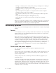
Supported operating positions To provide proper air flow to internal components, you must position your computer in one of the positions as illustrated below.
v Outside the United States and Canada, contact your IBM reseller or IBM marketing representative. Handling static-sensitive devices Static electricity, although harmless to you, can seriously damage computer components and options. When you add an option, do not open the static-protective package containing the option until you are instructed to do so. When you handle options and other computer components, take these precautions to avoid static electricity damage: v Limit your movement.
Installing external options This section shows the various external connectors on your computer to which you can attach external options, such as external speakers, a printer, or a scanner. For some external options, you must install additional software in addition to making the physical connection.
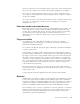
Locating the connectors on the rear of your computer The following illustration shows the locations of the connectors on the rear of the computer.
Connector Description Mouse connector Used to attach a mouse, trackball, or other pointing device that uses a standard mouse connector. Keyboard connector Used to attach a keyboard that uses a standard keyboard connector. Parallel connector Used to attach a parallel printer, parallel scanner, or other devices that use a 25-pin parallel connector. Serial connector Used to attach an external modem, serial printer, or other devices that use a 9-pin serial connector.
Opening the cover Important: Read “Important safety information” on page v and “Handling static-sensitive devices” on page 6 before opening the cover. To open the computer cover: 1. Remove any media (DVDs, CDs, or tapes) from the drives, shut down your operating system, and turn off all attached devices and the computer. 2. Unplug all power cords from electrical outlets. 3. Disconnect all cables attached to the computer.
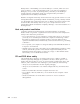
Locating components The following illustration will help you locate the various components in your computer. 1 PCI riser 2 Power supply assembly 3 Optical drive eject button 4 Optical drive 5 Hard disk drive 6 Cable clip 7 Fan bracket assembly Identifying parts on the system board The system board (sometimes called the planar or motherboard) is the main circuit board in your computer.
The following illustration shows the locations of parts on the system board.
2. Pivot the drive bay assembly upward to gain access to the system board. 3. To locate the memory connectors. See “Identifying parts on the system board” on page 11. 4. Open the retaining clips. 5. Make sure that the notch 1 on the memory module aligns correctly with the connector key 2 on the system board. Push the memory module straight down into the connector until the retaining clips close. Chapter 1.
What to do next: v To work with another option, go to the appropriate section. v To complete the installation, go to “Closing the cover and connecting the cables” on page 23. Installing a PCI adapter This section provides information and instructions for installing a PCI adapter. Your computer has a riser card with one PCI expansion connector. To install an adapter: 1. Open the cover. See “Opening the cover” on page 10. 2. Pivot the drive bay assembly upward to gain access to the system board. 3.
5. Pull upward on the blue handle provided to remove the PCI riser from the computer. 6. Pivot the adapter latch upward then remove the slot cover for the expansion connector. 7. Remove the adapter from its static-protective package. 8. Install the adapter into the expansion connector in the PCI riser. 9. Pivot the adapter latch down to retain the adapter. 10. Reinstall the PCI riser and the adapter. What to do next: v To work with another option, go to the appropriate section.
Installing internal drives This section provides information and instructions for removing and replacing internal drives. Internal drives are devices that your computer uses to read and store data. Your computer does not have the capacity to install additional drives but you might want to install higher capacity drives or a different type of drive to enable your computer to read other types of media.
2. Push the optical drive eject button and slide the optical drive out of the front of the computer. 3. Install the new drive into the bay. What to do next: v To work with another option, go to the appropriate section. v To complete the installation, go to “Closing the cover and connecting the cables” on page 23. Removing and replacing a hard disk drive To remove and replace a hard disk drive, do the following: 1. Open the cover. See “Opening the cover” on page 10. Chapter 1.
2. Pivot the drive bay assembly upward to gain access to the hard disk drive. 3. Disconnect the signal and power cables from the rear of the hard disk drive. 4. Lift the hard disk drive and bracket up to remove it from the drive bay. 5. Note the orientation of the hard disk drive in the plastic bracket. 6. Remove the drive by flexing the plastic enough to slide the drive out. 7. Install the hard disk drive into the plastic bracket by flexing the plastic enough to slide the drive in. 8.
Note: A serial ATA hard disk drive does not have a master/slave jumper. 10. Depending on the type of drive you are installing, go to “Connecting a parallel ATA hard disk drive” or “Connecting a serial ATA hard disk drive.” Connecting a parallel ATA hard disk drive 1. Locate the two-connector signal cable that comes with your computer or with the new drive. 2. Locate the hard drive cable connector on the system board. See “Identifying parts on the system board” on page 11. 3.
Security features To help prevent hardware theft and unauthorized access to your computer, several security options are available. In addition to a physical lock, unauthorized use of your computer can be prevented by a software lock that locks the keyboard until a correct password is typed in. Make sure that any security cables you install do not interfere with other computer cables.
Changing the battery Your computer has a special type of memory that maintains the date, time, and settings for built-in features, such as parallel-port assignments (configuration). A battery keeps this information active when you turn off the computer. The battery normally requires no charging or maintenance throughout its life; however, no battery lasts forever. If the battery fails, the date, time, and configuration information (including passwords) are lost.
7. Install the new battery. 8. Replace the fan bracket assembly. 9. Close the cover, and plug in the power cord. See “Closing the cover and connecting the cables” on page 23. Note: When the computer is turned on for the first time after battery replacement, an error message might be displayed. This is normal after replacing the battery. 10. Turn on the computer and all attached devices. 11. Use the IBM Setup Utility program to set the date and time and any passwords.
6. Locate the Clear CMOS/Recovery jumper on the system board. See “Identifying parts on the system board” on page 11. 7. Move the jumper from the standard position (pins 1 and 2) to the maintenance or configure position (pins 2 and 3). 8. Close the cover and connect the power cord. See “Closing the cover and connecting the cables.” 9. Restart the computer, leave it on for approximately 10 seconds. Turn off the computer by holding the power switch for approximately 5 seconds. The computer will turn off. 10.
Attention: To prevent overheating and possible component damage, always attach the floor stand when placing the computer in the vertical position. 7. Reconnect the external cables and power cords to the computer. See “Locating the connectors on the rear of your computer” on page 8. 8. To update the configuration, see Chapter 2, “Using the IBM Setup Utility program,” on page 25.
Chapter 2. Using the IBM Setup Utility program The IBM Setup Utility program is stored in the electrically erasable programmable read-only memory (EEPROM) of your computer. The IBM Setup Utility program is used to view and change the configuration settings of your computer, regardless of which operating system you are using. However, the operating-system settings might override any similar settings in the IBM Setup Utility program.
User password The user password feature deters unauthorized persons from gaining access to your computer. Administrator password Setting an administrator password deters unauthorized persons from changing configuration settings. If you are responsible for maintaining the settings of several computers, you might want to set an administrator password. After you set an administrator password, a password prompt is displayed each time you try to access the IBM Setup Utility program.
Using IDE Drives Setup In addition to listing the different IDE devices, there are options for configuring the serial and parallel IDE controllers. Parallel ATA Serial ATA Native Mode Operation This setting allows the user to disable one or both of the parallel IDE controllers. This setting allows the user to disable the serial ATA controller. This setting is only available when the serial ATA controller is enabled.
1. Start the IBM Setup Utility program (see “Starting the IBM Setup Utility program” on page 25). 2. Select Startup. 3. Select Startup Sequence. See the information displayed on the right side of the screen. 4. Select the sequence of devices for the Primary Startup Sequence, the Automatic Startup Sequence, and the Error Startup Sequence. 5. Select Exit from the IBM Setup Utility menu and then Save Settings.
Appendix A. Updating system programs This appendix contains information about updating system programs and how to recover from a POST/BIOS update failure. System programs System programs are the basic layer of software that is built into your computer. They include the power-on self-test (POST), the basic input/output system (BIOS) code, and the IBM Setup Utility program. POST is a set of tests and procedures that is performed each time you turn on your computer.
5. Under Download files - BIOS by date, click your machine type. 6. Scroll down and look for a .txt file that has instructions for Flash BIOS update from the operating system. Click the .txt file. 7. Print these instructions. This is very important since they are not on the screen after the download begins. 8. From your browser, Click Back to return to the list of files. Carefully follow the printed instructions to download, extract, and install the update.
the series of beeps will end, and the system will automatically turn off. Remove the diskette from the USB diskette drive. 11. Repeat steps 2 through 6 on page 30. 12. Move the Clear CMOS/Recovery jumper to its original position. 13. Close the cover and reconnect all power cords and cables that were disconnected. 14. Turn on the computer to restart the operating system. Appendix A.
32 User Guide
Appendix B. Cleaning the mouse This appendix provides instructions on how to clean your mouse. The procedure will be different depending on which type of mouse you have. Cleaning an optical mouse If you experience some problems with your optical mouse, check the following: 1. Turn the mouse over and look carefully at the lens area. a. If there is a smudge on the lens, gently clean the area with a plain cotton swab or plain q-tip. b.
3. Place your hand over the retainer ring and ball 2 , and then turn the mouse over, top side up, so that the retainer ring and ball fall out into your hand. 4. Wash the ball in warm, soapy water then dry it with a clean cloth. Blow air carefully into the ball cage 4 to dislodge dust and lint. 5. Look for a build up of dirt on the plastic rollers 3 inside the ball cage. This build up usually appears as a stripe running across the middle of the rollers. 6.
Appendix C. Manual modem commands The following section lists commands for manually programming your modem. Commands are accepted by the modem while it is in Command Mode. Your modem is automatically in Command Mode until you dial a number and establish a connection. Commands may be sent to your modem from a PC running communication software or any other terminal devices. All commands sent to the modem must begin with AT and end with ENTER.
Command Function H1 Force modem off-hook (make busy) Note: H1 command is not supported for Italy I_ L_ M_ I0 Display product-identification code I1 Factory ROM checksum test I2 Internal memory test I3 Firmware ID I4 Reserved ID L0 Low speaker volume L1 Low speaker volume L2 Medium speaker volume L3 High speaker volume M0 Internal speaker off M1 Internal speaker on until carrier detected M2 Internal speaker always on M3 Internal speaker on until carrier detected and off while d
Extended AT commands Command Function &C0 Force Carrier Detect Signal High (ON) &C1 Turn on CD when remote carrier is present &D0 Modem ignores the DTR signal &D1 Modem returns to Command Mode after DTR toggle &D2 Modem hangs up, returns to the Command Mode after DTR toggle &D3 Resets modem after DTR toggle &F_ &F Recall factory default configuration &G_ &G0 Guard tone disabled &G1 Guard tone disabled &G2 1800 Hz guard tone &K0 Disable flow control &K3 Enable RTS/CTS hardware flow
Command Function &W_ %E_ &V1 Display Last Connection Statistics &W0 Stores the active profile as Profile 0 &W1 Stores the active profile as Profile 1 %E0 Disable auto-retrain %E1 Enable auto-retrain +MS? Displays the current Select Modulation settings +MS=? Displays a list of supported Select Modulation options +MS=a,b,c,e,f Select modulation where: a=0, 1, 2, 3, 9, 10, 11, 12, 56, 64, 69; b=0-1; c=300-56000; d=30056000; e=0-1; and f=0-1. A, b, c, d, e, f default=12, 1, 300, 56000, 0, 0.
Fax Class 1 commands +FAE=n Data/Fax Auto Answer +FCLASS=n Service Class +FRH=n Receive data with HDLC framing +FRM=n Receive data +FRS=n Receive silence +FTH=n Transmit data with HDLC framing +FTM=n Transmit data +FTS=n Stop transmission and wait Fax Class 2 commands +FCLASS=n Services class. +FAA=n Adaptive answer. +FAXERR Fax error value. +FBOR Phase C data bit order. +FBUF? Buffer size (read only). +FCFR Indicate confirmation to receive. +FCLASS= Service class.
+FPHCTO Phase C time out. +FPOLL Indicates polling request. +FPTS: Page transfer status. +FPTS= Page transfer status. +FREV? Identify revision. +FSPT Enable polling. +FTSI: Report the transmit station ID.
Attention Switzerland User: If your Swisscom phone line does not have Taxsignal switched OFF, modem function may be impaired. The impairment may be resolved by a filter with the following specifications: Telekom PTT SCR-BE Taximpulssperrfilter-12kHz PTT Art. 444.112.7 Bakom 93.0291.Z.N Appendix C.
42 User Guide
Appendix D. Customer replaceable unit (CRU) parts list For your computer, the following parts are designated customer replaceable unit (CRU) parts. Refer to the warranty section of your Quick Reference for more information. Tier 1 CRUs All option and adapter cards All bezels All cables All hard disk drives and optical drives All keyboards All line cords All memory All mice All keylocks All RJ11 connector adapters Battery, 3.
44 User Guide
Appendix E. Notices IBM may not offer the products, services, or features discussed in this document in all countries. Consult your local IBM representative for information on the products and services currently available in your area. Any reference to an IBM product, program, or service is not intended to state or imply that only that IBM product, program, or service may be used.
Television output notice The following notice applies to models that have the factory-installed television-output feature. This product incorporates copyright protection technology that is protected by method claims of certain U.S. patents and other intellectual property rights owned by Macrovision Corporation and other rights owners.
Index A K adapters installing 14 peripheral component interconnect (PCI) slots 14 audio line in connector 9 audio line out connector 9 audio, subsystem 2 keyboard connector 5 9 L locating components 11 M B boot-block recovery memory dual inline memory modules (DIMMs) 12 installing 12 system 12 memory modules, installing 12 modem Basic AT commands 35 Extended AT commands 37 Fax Class 1 commands 39 Fax Class 2 commands 39 MNP/V.42/V.42bis/V.
security (continued) integrated cable lock 20 security profile by device 26 serial connector 9 system board connectors 12 identifying parts 11 location 12 memory 5, 12 system programs 29 U USB connectors 9 using, security profile by device V video, subsystem 48 User Guide 2 26
Part Number: 19R2375 Printed in USA (1P) P/N: 19R2375