IBM Mobile Systems ThinkPad 600/600E (2645) Hardware Maintenance Manual June 1999 S10L-9619-03
Note Before using this information and the product it supports, be sure to read the general information under “Notices” on page 117.
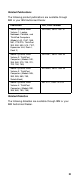
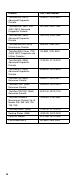
Related Publications The following product publications are available through IBM or your IBM Authorized Dealer.
iv Diskette Part, Form Number ThinkPad 300 (2615) Advanced Diagnostics Diskette 33G9361, S33G-9361 ThinkPad 350, 350C, 425, 425C (2618) Advanced Diagnostics Diskette A211000, GA21-1000 ThinkPad 365 (2625) Advanced Diagnostics Diskette 76H7578, S30H-2498 ThinkPad 380/385 (2635) Maintenance Diskette 06J0333, S06J-0333 ThinkPad 390/i Series 1700 (2626, 2627) Diagnostic and Utilities Diskettes 10L9942, S10L-9942 ThinkPad 500 (2603) Advanced Diagnostics Diskette 71G3702, S71G-3702 ThinkPad 510 (26
Contents General Descriptions . . . . . . . . . . . . . Introduction . . . . . . . . . . . . . . . . . . . Important Service Information . . . . . . . . . Drive and Diskette Compatibility Matrix . . . . Safety Notices (Multi-lingual Translations) . . . Safety Information . . . . . . . . . . . . . . Laser Compliance Statement . . . . . . . . . . Read This First . . . . . . . . . . . . . . . . . FRU Replacement Notices . . . . . . . . . . . LCD Replacement Notice . . . . . . . . . . Screw Notices . . . . . .
Beep Symptoms . . . . . . . . . . . . . Audio-Related Symptoms . . . . . . . . CD-ROM-Related Symptoms . . . . . . . Function-Related Symptoms . . . . . . . Indicator-Related Symptoms . . . . . . . Infrared-Related Symptoms . . . . . . . . Keyboard- or TrackPoint-Related Symptoms LCD-Related Symptoms . . . . . . . . . Modem (DSP)-Related Symptoms . . . . PC Card-Related Symptoms . . . . . . . Peripheral-Device-Related Symptoms . . . Power-Related Symptoms . . . . . . . . Other Symptoms . . . . . . . . . . .
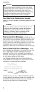
Introduction General Descriptions This chapter includes the descriptions for all ThinkPad models. Some descriptions might not apply to the particular computer. Introduction Important Service Information Important Diskette fixes are customer installable. The diskette fixes are located on the PC Company Bulletin Board Service (BBS). The direct phone line for modem connection is 919-557-0001 or tieline 255-0001.
Introduction Attention A customized setup configuration (other than default settings) may exist on the computer you are servicing. Running Automatic Configuration may alter those settings. Note the current configuration settings (using the View Configuration option) and verify that the settings are in place when service is complete. Hard Disk Drive Replacement Strategy: Always try to run a low-level format before replacing a hard disk drive.
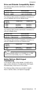
Introduction Drive and Diskette Compatibility Matrix The following table provides identification information for 3.5-inch drives. Diskette Drive Identifying Mark 3.5-Inch - 1.44MB 3.5-Inch - 2.88MB 1.44 on the eject button 2.88 on the eject button The following table provides compatibility information for 3.5-inch diskettes and 3.5-inch diskette drives. Diskette Capacity 1.44MB Drive 2.88MB Drive 1.0MB 2.0MB 4.
Introduction Safety Notice 1 Before the computer is powered-on after FRU replacement, make sure all screws, springs, or other small parts are in place and are not left loose inside the computer. Verify this by shaking the computer and listening for rattling sounds. Metallic parts or metal flakes can cause electrical shorts. Avant de remettre l'ordinateur sous tension après remplacement d'une unité en clientèle, vérifiez que tous les ressorts, vis et autres pièces sont bien en place et bien fixées.
Introduction Safety Notice 2 Some standby batteries contain a small amount of nickel and cadmium. Do not disassemble it, recharge it, throw it into fire or water, or short-circuit it. Dispose of the battery as required by local ordinances or regulations. Use only the battery in the appropriate parts listing. Use of an incorrect battery can result in ignition or explosion of the battery. Certaines batteries de secours contiennent du nickel et du cadmium.
Introduction Safety Notice 3 The battery pack contains small amounts of nickel. Do not disassemble it, throw it into fire or water, or short-circuit it. Dispose of the battery pack as required by local ordinances or regulations. Use only the battery in the appropriate parts listing when replacing the battery pack. Use of an incorrect battery can result in ignition or explosion of the battery. La batterie contient du nickel. Ne la démontez pas, ne l'exposez ni au feu ni à l'eau.
Introduction Safety Notice 4 The lithium battery can cause a fire, explosion, or severe burn. Do not recharge it, remove its polarized connector, disassemble it, heat it above 100°C (212°F), incinerate it, or expose its cell contents to water. Dispose of the battery as required by local ordinances or regulations. Use only the battery in the appropriate parts listing. Use of an incorrect battery can result in ignition or explosion of the battery. La pile de sauvegarde contient du lithium.
Introduction Safety Notice 5 If the LCD breaks and the fluid from inside the LCD gets into your eyes or on your hands, immediately wash the affected areas with water for at least 15 minutes. Seek medical care if any symptoms from the fluid are present after washing. Si le panneau d'affichage à cristaux liquides se brise et que vous recevez dans les yeux ou sur les mains une partie du fluide, rincez-les abondamment pendant au moins quinze minutes.
Introduction Safety Notice 6 To avoid shock, do not remove the plastic cover that surrounds the lower portion of the inverter card. Afin d'éviter tout risque de choc électrique, ne retirez pas le cache en plastique protégeant la partie inférieure de la carte d'alimentation. Aus Sicherheitsgründen die Kunststoffabdeckung, die den unteren Teil der Spannungswandlerplatine umgibt, nicht entfernen.
Introduction Safety Notice 8 Before removing any FRU, power-off the computer, unplug all power cords from electrical outlets, remove the battery pack, then disconnect any interconnecting cables. Avant de retirer une unité remplaçable en clientèle, mettez le système hors tension, débranchez tous les cordons d'alimentation des socles de prise de courant, retirez la batterie et déconnectez tous les cordons d'interface.
Introduction Place removed covers and other parts in a safe place, away from all personnel, while you are servicing the machine. Keep your tool case away from walk areas so that other people will not trip over it. Do not wear loose clothing that can be trapped in the moving parts of a machine. Ensure that your sleeves are fastened or rolled up above your elbows. If your hair is long, fasten it.
Introduction If you need to work on a machine that has exposed electrical circuits, observe the following precautions: – Ensure that another person, familiar with the power-off controls, is near you. – – – 12 Attention: Another person must be there to switch off the power, if necessary. Use only one hand when working with powered-on electrical equipment; keep the other hand in your pocket or behind your back. Attention: There must be a complete circuit to cause electrical shock.
Introduction Safety Inspection Guide: The intent of this inspection guide is to assist you in identifying potentially unsafe conditions on these products. Each machine, as it was designed and built, had required safety items installed to protect users and service personnel from injury. This guide addresses only those items. However, good judgment should be used to identify potential safety hazards due to attachment of non-IBM features or options not covered by this inspection guide.
Introduction Protect against ESD damage by equalizing the charge so that the machine, the part, the work mat, and the person handling the part are all at the same charge. Notes 1. Use product-specific ESD procedures when they exceed the requirements noted here. 2. Make sure that the ESD protective devices you use have been certified (ISO 9000) as fully effective. When handling ESD-sensitive parts: Keep the parts in protective packages until they are inserted into the product.
Introduction Elsewhere, the drive is certified to conform to the requirements of the International Electrotechnical Commission (IEC) 825 and CENELEC EN 60 825 for Class 1 laser products. When a CD-ROM drive is installed, note the following. CAUTION: Use of controls or adjustments or performance of procedures other than those specified herein might result in hazardous radiation exposure.
Introduction Some CD-ROM drives contain an embedded Class 3A or Class 3B laser diode. Note the following. DANGER: Laser radiation when open. Do not stare into the beam, do not view directly with optical instruments, and avoid direct exposure to the beam. Radiação por raio laser ao abrir. Não olhe fixo no feixe de luz, não olhe diretamente por meio de instrumentos óticos e evite exposição direta com o feixe de luz. Rayonnement laser si carter ouvert.
Read This First Read This First Before you go to the checkout guide, be sure to read this section. Important Notes Only certified trained personnel should service the computer. Read the entire FRU removal and replacement page before replacing any FRU. Use new nylon-coated screws when you replace FRUs. Be extremely careful during such write operations as copying, saving, or formatting.
Read This First Before checking problems with the computer, determine whether the damage is covered under the warranty by referring to the following: Note During the warranty period, the customer may be responsible for repair costs if the computer damage was caused by misuse, accident, modification, unsuitable physical or operating environment, or improper maintenance by the customer.
FRU Replacement Notices FRU Replacement Notices This section contains notices for removal and replacement. Read this section carefully before replacing any FRU. LCD Replacement Notice The TFT LCD for the computer contains over 2,359,296 thin-film transistors (TFTs). A small number of missing, discolored, or lighted dots (on all the time) is characteristic of TFT LCD technology, but excessive pixel problems can cause viewing concerns.
FRU Replacement Notices Torque driver If you have a torque driver, refer to the “Torque” column with each step. Make sure you use the correct screw, and tighten all screws firmly to the torque shown in the table if you have a torque screwdriver. Never use a screw that you removed. Use a new one.
FRU Replacement Notices You must restore each of those serial numbers except the system board serial number to its original number when replacing the system board. To save the original serial numbers, do the following: 1. Boot from DOS, or open an MS-DOS prompt. 2. Insert the ThinkPad Hardware Maintenance Diskette Version 1.05 into the diskette drive. 3. Enter A:\SERUPDT.EXE at the DOS prompt. The usage of this tool is displayed. Note: SERUPDT.EXE is in the ThinkPad Hardware Maintenance Diskette Version 1.
FRU Replacement Notices 4. Press Ctrl + G. The UUID menu appears. 5. Press F5 to generate a new UUID, and press Enter to overwrite it to EEPROM. CPU Card Replacement Notice (600E and 770X Only) You must restore the CPU card serial number to its original number, when the CPU card is replaced. To save and restore the CPU card serial number, follow the instruction in “Serial Numbers” on page 20.
Related Service Information Related Service Information This section provides information about the following: “How to Use Error Messages” “How to Diagnose Multiple FRUs” “Reset Switch” “Running a Low-Level Format” “Service Web Site” on page 24 “Passwords” on page 24 “Power Management Features” on page 25 “Fn Key Combinations” on page 29 How to Use Error Messages Use the error codes displayed on the screen to diagnose failures.
Related Service Information 1. Insert the ThinkPad Hardware Maintenance Diskette Version 1.05 or a later version into the diskette drive and power on the computer. 2. Select Format the hard disk from the main menu. 3. Select the drive from the menu. 4. Follow the instructions on the screen. Service Web Site When the latest maintenance diskette and the system program service diskette are available, they will be posted on: Maintenance diskette: http://www.pc.ibm.com/files/searchfiles.
Related Service Information power-on password at the supervisor password prompt. In this case, the Password, Start up, Network, and Initialize or Asset ID (for some models) icons cannot be selected. Note: The supervisor password and hard disk password cannot be replaced if they are forgotten. If the customer forgets the supervisor password, the system board must be replaced. If the customer forgets the hard disk password, the hard disk drive must be replaced.
Related Service Information Standby Mode: In standby mode, the following occurs: The LCD backlight turns off. The hard disk drive motor stops. The speaker is muted. Note: Standby mode in Windows 98 is called suspend mode in Windows 95. The computer enters standby mode when the Fn + F3 keys are pressed. The computer exits standby and resumes normal operation when any key is pressed.
Related Service Information independent of the operating system, so the computer might behave differently from your setting if you set the low-battery alarm. The computer chooses appropriately between your setting and the default setting. Note: The computer cannot enter suspend mode if it is attached to a docking station. The following events cause the computer to resume operation from suspend mode: The Fn key is pressed. The LCD cover is opened.
Related Service Information The following events cause the computer to enter hibernation mode: The Fn + F12 keys are pressed. The Hibernation button is selected in the Fuel-Gauge program. The power switch is turned off when hibernation mode is set to Hibernate by Power Switch in the Windows 98 Power Management Properties window. The timer conditions are satisfied in suspend mode (for operating systems other than Windows 98).
Related Service Information Fn Key Combinations The following table shows the Fn key and function key combinations and their corresponding functions. The Fn key works independently from the operating system. The operating system obtains the status through the system management interface to control the system. Fn + Description F1 Reserved. F2 Turn Fuel-Gauge display on or off. F3 Turn standby mode on. F4 Turn suspend mode on. F5 Reserved. F6 Reserved.
Checkout Guide Checkout Guide Use the following procedure as a guide for computer problems. Note: The diagnostic tests are intended to test only IBM products. Non-IBM products, prototype cards, or modified options can give false errors and invalid system responses. 1. Obtain the failing symptoms in as much detail as possible. 2. Verify the symptoms by attempting to re-create the failure by running the diagnostic test or by repeating the same operation.
Checkout Guide Symptoms (Verified) Go To Symptoms cannot be re-created (intermittent problems). Use the customer-reported symptoms and go to “Symptom-to-FRU Index” section. Audio Checkout ISA Audio Check Out 1. Go to the diagnostic menu by selecting Test in the Easy-Setup menu. 2. Select Audio and run the diagnostic tests. 3. If the test detects a audio problem, replace the system board. PCI Audio Check Out 1. Power off the computer. 2. Insert the ThinkPad Hardware Maintenance Diskette Version 1.
Checkout Guide 7. Insert the blank diskette when instructed and follow the instructions on the screen. 8. If the controller test detects an error, FRU code 10 appears. Replace the system board. 9. If the controller test runs without errors, the drive read/write tests start automatically. If a drive test detects an error, FRU code 50 for FDD-1 or 51 for FDD-2 appears. If the diskette itself is known to be good, replace the drive. Fan Checkout To check the fan, do the following: 1. Start Easy-Setup. 2.
Checkout Guide the keyboard test. See “Running the Diagnostics” on page 39 for details. Note: When the Fn key is pressed, a black square briefly appears. If the tests detect a keyboard problem, do the following one at a time to correct the problem. Do not replace a nondefective FRU: 1. 2. 3. 4. Reseat the keyboard cable. Replace the keyboard. Replace the card that the keyboard is connected to. Replace the system board.
Checkout Guide If an error appears: If the computer don't have the base memory slot, replace the system board. If the computer has the base memory slot, remove the DIMM installed in the base memory slot and go to step 2 on page 33. Then if an error appears, replace the system board. If an error does not appear, continue the following procedures. 5. Power off the computer and reinstall the DIMM one by one; then power on the computer. Verify the memory size; then test the memory.
Checkout Guide Port Replicator Checkout Use the following procedure to isolate a port replicator problem. The port replicator attaches to the system expansion connector at the rear of the computer: 1. Power off the computer. 2. Remove the failing devices from the port replicator. 3. Unplug the AC Adapter from the port replicator, if attached. 4. Remove the port replicator from the computer. 5. Reconnect the failing device directly to the computer.
Checkout Guide 3. Disconnect the AC Adapter and install the charged battery pack; then check that power is supplied by the battery pack.
Checkout Guide pack. If the charge indicator or icon still does not turn on, replace the battery pack. If the charge indicator still does not turn on, replace either the system board or DC-DC card that the battery is connected to. Then reinstall the battery pack. If the reinstalled battery pack is not charged, go to the next section.
Checkout Guide Checking the Backup Battery: Do the following: 1. Power off the computer and unplug the AC Adapter from the computer. 2. Turn the computer upside down. 3. Remove the backup battery (see “Removal and Replacement” section of each model). 4. Measure the voltage of the backup battery. See the following figure. Note: Be careful not to measure the wrong side of the backup battery. Wire Voltage (V dc) Red +2.5 to +3.2 Black Ground If the voltage is correct, replace the system board.
Running the Diagnostics 2. If FRU code 10 appears, replace the system board but do not replace the CPU card. Remove the CPU card from the old system board and install it to the new system board. 3. If FRU code 11 appears, reseat the CPU card. 4. Rerun the test to verify the fix. 5. If FRU code 11 remains, replace the CPU card. If this procedure does not correct the problem, go to the “Undetermined Problems” section for each model.
Running the Diagnostics Tool Name Part Number PC test card 35G4703 Tri-connector wrap plug 72X8546 USB parallel test cable 05K2580 Use either the TrackPoint or the cursor-moving keys to interact with the tests. The Enter key works the same as selecting the OK icon to reply OK. 1. Press and hold F1; then power on the computer. Hold F1 down until the Easy-Setup menu appears. 2. Click on Test. The basic diagnostic menu appears. 3. Click on a device to run the test.
Running the Diagnostics PC Card Slots Test The green LED on the PC test card turns on when the PC Card slot test is running. If the LED does not turn on, check that the card is installed correctly by reseating it. If the LED still does not turn on after the card is reseated, try using another slot for the test. If the LED still does not turn on and the test fails, replace the FRU shown by the diagnostic error code. Universal Serial Bus (USB) Test At the advanced diagnostic window, do the following: 1.
Running the Diagnostics USB ports of the docking station and click on USB-3 and USB-4. Displaying the Error Log Diagnostic errors are printed on a printer attached to the parallel port when the error is detected. The error is also logged in the system memory. Use the following procedure to display the errors: 1. 2. 3. 4. Enter the advanced diagnostic test. Press Ctrl+E. The error log appears. To exit the screen, click on Exit or press Esc. The error log is not saved when system power is turned off.
Running the Diagnostics The device ID and error code indicate the detailed portion of the FRU that caused the error. If replacing a FRU does not correct the problem, see the device ID or error code from the previous failure. If they have changed, the cause might be that the new FRU is defective or that the FRU was incorrectly installed. Device ID: If an error is detected by the diagnostic tests, a three-digit device ID is displayed, indicating the suspected device.
Running the Diagnostics Icon Device ID Suspected Device USB-1 154 USB USB-2 155 External USB USB-3 156 External USB USB-4 157 External USB Audio (PCI) 158 PCI audio CDROM-1 215 CD-ROM CDROM-2 216 External CD-ROM DVD-1 217 DVD drive DVD-2 218 External DVD drive Note: * Some ThinkPad 600E computers support only one FDD at a time. The icon of the diskette drive for such models is FDD instead of FDD-1 or FDD-2.
Running the Diagnostics FRU Code FRU 50 1. Reseat the diskette drive (FDD-1) 2. Diskette drive (FDD-1) 51 1. Reseat the diskette drive (FDD-2) 2. Diskette drive (FDD-2) 60 1. Reseat the hard disk drive (HDD-1) 2. Hard disk drive (HDD-1) 61 1. Reseat the hard disk drive in the docking station (HDD-3) 2. Hard disk drive in the docking station (HDD-3) 62 1. Reseat the hard disk drive in the docking station (HDD-2) 2. Hard disk drive in the docking station (HDD-2) 63 1.
Running the Diagnostics 46
Running the Diagnostics ThinkPad 600 This chapter includes the descriptions for the ThinkPad 600 series computer. Model-Unique Functions . . . . . . . . . . . Product Overview . . . . . . . . . . . . Status Indicators . . . . . . . . . . . . . Symptom-to-FRU Index . . . . . . . . . . . Numeric Error Codes . . . . . . . . . . . Beep Symptoms . . . . . . . . . . . . . Audio-Related Symptoms . . . . . . . . CD-ROM-Related Symptoms . . . . . . . Function-Related Symptoms . . . . . . .
Running the Diagnostics Model 600 . . . . LCD FRU (TFT) . Model 600E . . . LCD FRU (TFT) . Keyboard . . . . Miscellaneous Parts Modem Kit . . . Common Parts List 48 . . . . . . . . . . . . . . . . . . . . . . . . . . . . . . . . . . . . . . . . . . . . . . . . . . . . . . . . . . . . . . . . . . . . . . . . . . . . . . . . . . . . . . . . . . . . . . . . . . . . . . . . . . . . . .
Model-Unique Functions Model-Unique Functions Product Overview The following table is an overview of the system features of the ThinkPad 600 series: Feature Description Processor For 600: Intel Pentium L2 cache Intel Pentium cache Intel Pentium cache Intel Pentium cache MMX 233 MHz, II 233 MHz, L2 II 266 MHz, L2 II 300 MHz, L2 For 600E: Bus Architecture Intel Pentium II 300 MHz, L2 cache with AGP Intel Mobile Pentium II 300PE MHz, L2 cache with AGP Intel Mobile Pentium II 366
Model-Unique Functions Feature Description Video For 600: 13.0-inch, 64K colors 1024×768 pixel HPA color LCD 12.1-inch, 64K colors, 800×600 pixel TFT color LCD 13.3-inch, 64K colors, 1024×768 pixel TFT color LCD For 600E: 13.3-inch, 16M colors 1024×768 pixel TFT color LCD Diskette Drive (External) 1.44 MB (3-mode), 3.5-inch Hard Disk Drive For 600: 3.2 GB, 2.5-inch, IDE interface 4.0 GB, 2.5-inch, IDE interface For 600E: CD-ROM/DVD Drive 4.0 GB, 2.5-inch, IDE interface 6.
Model-Unique Functions Status Indicators The system status indicators show the current computer status in different colors (green and orange): Symbol Color Meaning .1/Battery Green The battery is fully charged. Orange The battery is charging. Blinking orange The battery needs charging. .2/Suspend Mode Green Suspend mode Blinking green Entering suspend mode .3/Hard Disk In Use Orange Data is read from or written to the hard disk drive. .
Symptom-to-FRU Index Symptom-to-FRU Index The symptom-to-FRU index lists the symptoms and errors and their possible causes. The most likely cause is listed first. Note: Perform the FRU replacement or actions in the sequence shown in the “FRU/Action in Sequence” column. If a FRU replacement did not solve the problem, put the original part back in the computer. Do not replace a nondefective FRU. This index can also help you determine the next possible FRUs to be replaced when servicing a computer.
Symptom-to-FRU Index Symptom / Error FRU / Action in Sequence 111 (I/O parity.) 1. Go to “Memory Checkout” on page 33. 2. Expansion unit or port replicator. 3. System board 11XX 1101: Serial_A test failure. 1. Serial device 2. Communication cable 3. System board 12XX 1201: Serial_B test failure. 1. System board (infrared) 158 (The hard disk password was not set even though the supervisor password is set.) Set the password for the hard disk drive.
Symptom-to-FRU Index Symptom / Error FRU / Action in Sequence 183 (Incorrect password entered at the supervisor password prompt.) Have the user examine the password. 184 (Power-on password check sum error.) Reset the power-on password in Easy-Setup. 185 (The startup sequence is not valid. Suspect that power was off when the startup sequence was being updated.) Reset the startup sequence in Easy-Setup. 186 1. System board 188, 189 (BAD EEPROM CRC #1. An incorrect checksum of the EEPROM is received.
Symptom-to-FRU Index Symptom / Error 1XX FRU / Action in Sequence 1. System board 2XX 201: Memory data error. 202: Memory line error 00–15. 203: Memory line error 16–23. 205: Memory test failure on on-board memory. 221: ROM to RAM remap error. 1. Go to “Memory Checkout” on page 33. 2. DIMM card 3. System board 225 (Unsupported memory module.) 1. Check if the supported DIMM is installed. 2. DIMM card 3. System board 301, 303, 304, 305, 3XX (301: Keyboard error.) 1.
Symptom-to-FRU Index Symptom / Error 808X 8081: PCMCIA presence test failure. (PCMCIA revision number also checked.) 8082: PCMCIA register test failure. 860X (Pointing device error when TrackPoint is disabled.) FRU / Action in Sequence 1. PC Card slot assembly 2. PCMCIA device 3. System board 1. External mouse 2. External keyboard 3. System board 8601: System bus error–8042 mouse interface. 8602: External mouse error. 8603: System bus error or mouse error.
Symptom-to-FRU Index Beep Symptoms Symptom / Error FRU / Action in Sequence Continuous beeps. 1. System board One beep and a blank, unreadable, or flashing LCD. 1. Reseat the LCD connector 2. LCD assembly 3. System board One beep, and the message “Unable to access boot source.” 1. Boot device 2. System board One long and two short beeps, and a blank or unreadable LCD. 1. System board 2. LCD assembly One long beep followed by four short beeps each time the power switch is operated.
Symptom-to-FRU Index Audio-Related Symptoms Symptom / Error FRU / Action in Sequence In OS/2, DOS, or Windows multimedia programs, no sound comes from the computer. (Only system beeps are heard at power-on.) Check that the device driver is installed correctly. CD-ROM-Related Symptoms Symptom / Error You hear a noise from the CD-ROM drive when the CD-ROM is spinning. FRU / Action in Sequence 1. CD-ROM drive 2. System board The CD-ROM tray does not open even if you press the CD-ROM eject button.
Symptom-to-FRU Index Symptom / Error FRU / Action in Sequence The CD-ROM does not work. Make sure that: The computer power is turned on and a compact disc is in the CD-ROM drive. The CD-ROM drive connector is firmly connected to the computer. The CD-ROM drive tray is firmly closed. The device drivers are correctly installed. If the CD-ROM drive in the docking station does not work, do the following: 1. Click on Start. 2.
Symptom-to-FRU Index Function-Related Symptoms Symptom / Error The system does not suspend or resume when the LCD is closed or opened. FRU / Action in Sequence 1. Go to “Suspend Mode” on page 26, and check that the computer can enter suspend mode. 2. Boot an operating system and press Fn+F4. If the computer enters suspend mode, suspect that the application program is not working properly. 3. LCD assembly 4. System board The battery Fuel-Gauge does not go higher than 90%.
Symptom-to-FRU Index Infrared-Related Symptoms Symptom / Error Unable to communicate using the Infrared (IR) Port. FRU / Action in Sequence 1. Make sure the setup for the IR is correct. Use the ThinkPad Configurations utility. 2. Make sure there are no fluorescent lights near the computer. The computer may receive optical noise from the fluorescent light. 3. Run the advanced diagnostic test. If an error occurs and a FRU code is displayed, replace the parts shown by the FRU code.
Symptom-to-FRU Index LCD-Related Symptoms Important The TFT LCD for the notebook computer contains over 2,359,296 thin-film transistors (TFTs). A small number of missing, discolored, or lighted dots (on all the time) is characteristic of TFT LCD technology, but excessive pixel problems can cause viewing concerns. The LCD should be replaced if the number of missing, discolored, or lighted dots in any background is 21 or more. Symptom / Error No beep, power-on indicator on, and a blank LCD during POST.
Symptom-to-FRU Index PC Card-Related Symptoms Symptom / Error PC Card does not work in either the upper slot or the lower slot. Diagnostic error code: FRU / Action in Sequence 1. Reseat the PCMCIA slot assembly. 2. PCMCIA slot assembly 3. System board DEV 080 ERR 33 FRU 7210 PCMCIA slot pin is damaged. PC Card does not work. PCMCIA slot assembly 1. Reseat the PC Card 2. Check that the PC Card is enabled in the ThinkPad Configuration program 3. Reseat the PCMCIA slot assembly. 4. PCMCIA slot assembly 5.
Symptom-to-FRU Index Power-Related Symptoms Symptom / Error FRU / Action in Sequence Power shuts down during operation. 1. Go to “Power Systems Checkout” on page 35. 2. Battery pack 3. Remove the battery pack and let it cool for 2 hours. 4. System board 5. Check the power outlet. The system does not power off. (See “Reset Switch” on page 23.) 1. Press the power shutdown switch. 2.
Symptom-to-FRU Index Verify that all attached devices are supported by the computer. Verify that the power supply being used at the time of the failure is operating correctly. (See “Power Systems Checkout” on page 35): 1. Power off the computer. 2. Visually check them for damage. If any problems are found, replace the FRU. 3. Remove or disconnect all of the following devices: a. Non-IBM devices b. Devices attached to the port replicator c. Printer, mouse, and other external devices d. Battery pack e.
FRU Removals and Replacements FRU Removals and Replacements This section contains information about removals and replacements: Do not damage any part. Only certified and trained personnel should service the computer. The arrows in the “Removals and Replacements” section show the direction of movement to remove a FRU, or to turn a screw to release the FRU. The arrows are marked in numeric order, in square callouts, to show the correct sequence of removal.
FRU Removals and Replacements 1010 Backup Battery Caution The backup battery is a lithium battery and can cause a fire, an explosion, or severe burns. Do not recharge it, remove its polarized connector, disassemble it, heat it above 100°C (212°F), incinerate it, or expose its cell contents to water. Dispose of the battery as required by local ordinances or regulations. Use of an incorrect battery can result in ignition or explosion of the battery. Note Loosen (but not remove) the screw .1/.
FRU Removals and Replacements 1020 DIMM 1 1 Top View 2 68
FRU Removals and Replacements 1030 Battery Pack Unlock Lock 1 2 ThinkPad 600 69
FRU Removals and Replacements 1040 Hard Disk Drive Attention Do not drop or apply any shock to the hard disk drive. The hard disk drive is sensitive to physical shock. Incorrect handling can cause damage and permanent loss of data on the drive. Before removing the drive, have the user make a backup copy of all the information on the drive if possible. Never remove the drive while the system is operating or is in suspend mode. 1 3 2 Step Screw (Quantity) Color Torque .
FRU Removals and Replacements 1050 UltraslimBay Device The artwork shows the FDD in the UltraslimBay, one of the CD-ROM drive, DVD Drive, battery pack, or HDD with adapter is available in the UltraslimBay. 1 2 When the security screw is installed In step .1/, use a 2.5-mm allen wrench to remove the security screw.
FRU Removals and Replacements 1060 Keyboard Assembly Battery Pack (1030) Hard Disk Drive (1040) CD-ROM Drive or Diskette Drive (1050) 1 2 3 4 5 Turn the computer right side up. Step Screw (Quantity) Color Torque .1/ M2.5 × 19.5 mm, nylon-coated (3) Black 4 kgcm .2/ M2.5 × 16 mm, nylon-coated (2) Black 4 kgcm .3/ M2.5 × 4.
FRU Removals and Replacements Step Screw (Quantity) Color Torque .4/ M2.5 × 3 mm, nylon-coated (4) Yellow 4 kgcm .5/ M2.5 × 4.
FRU Removals and Replacements 1070 Keyboard Battery Pack (1030) Hard Disk Drive (1040) CD-ROM Drive or Diskette Drive (1050) Keyboard Assembly (1060) Note When you tear off the insulator in step .1/, do it gently for it is reused. 2 3 4 1 2 Bottom view 4 Step Screw (Quantity) Color Torque .2/ M2.
FRU Removals and Replacements 1080 Speakers Battery Pack (1030) Hard Disk Drive (1040) CD-ROM Drive or Diskette Drive (1050) Keyboard Assembly (1060) Note In step .1/, remove the insulator on the left speaker. 2 3 2 4 1 4 Bottom view Step Screw (Quantity) Color Torque .2/ M2.
FRU Removals and Replacements Note When replacing the right speaker, see the following artwork for its cable routing.
FRU Removals and Replacements 1085 Speaker Cable Battery Pack (1030) Hard Disk Drive (1040) CD-ROM Drive or Diskette Drive (1050) Keyboard Assembly (1060) Note In step .1/, remove the insulator on the left speaker. 2 4 1 3 Bottom view Step Screw (Quantity) Color Torque .2/ M2.
FRU Removals and Replacements 1090 LCD Assembly Battery Pack (1030) Hard Disk Drive (1040) CD-ROM Drive or Diskette Drive (1050) Keyboard Assembly (1060) Note For the LCD FRU removals and replacement, go to “2010 LCD Front Cover” on page 88. 1 3 4 3 2 5 6 7 Step Screw (Quantity) Color Torque .1/ M2.5 × 4.8 mm, nylon-coated (4) Black 4 kgcm .3/ M2.5 × 4.8 mm, nylon-coated (4) Black 4 kgcm .4/ M2.5 × 4.
FRU Removals and Replacements 1100 PC Card (PCMCIA) Slot Assembly Battery Pack (1030) Hard Disk Drive (1040) CD-ROM Drive or Diskette Drive (1050) Keyboard Assembly (1060) 2 1 Connector 3 Step Screw (Quantity) Color Torque .1/ M2.0 × 9.5 mm, nylon-coated (4) Black 2.
FRU Removals and Replacements 1110 Modem Card Battery Pack (1030) Hard Disk Drive (1040) CD-ROM Drive or Diskette Drive (1050) Keyboard Assembly (1060) 1 Connector 2 3 Step Screw (Quantity) Color Torque .1/ M2.5 × 4.
FRU Removals and Replacements 1115 System Kit for RFID Note This FRU is only for 600E (2645-AAU) only.
FRU Removals and Replacements 2 3 1 Step Screw (Quantity) Color Torque .2/ M2.5 × 4.
FRU Removals and Replacements 1130 CPU Card and Fan Battery Pack (1030) Hard Disk Drive (1040) CD-ROM Drive or Diskette Drive (1050) Keyboard Assembly (1060) Step Screw (Quantity) Color Torque .1/ M2.0 × 9.5 mm, nylon-coated (1) Black 2.5 kgcm .3/ M2.0 × 9.5 mm, nylon-coated (4) Black 2.
FRU Removals and Replacements 5 Fan 6 CPU card Step Screw (Quantity) Color Torque .5/ M2.0 × 4.0 mm, nylon-coated (2) Black 2.5 kgcm Note When you replace the CPU card, press only on the places indicated in the figure. Press both sides at the same time. Do not press only one side or any other part of the card..
FRU Removals and Replacements 1140 Guide Rail, Mic. Cable, or TV Out Card Battery Pack (1030) Hard Disk Drive (1040) CD-ROM Drive or Diskette Drive (1050) Keyboard Assembly (1060) Note TV out card is available for 600E model only. For 600 Step Screw (Quantity) Color Torque .4/ M2.0 × 9.5 mm, nylon-coated (1) Black 2.5 kgcm .5/ M2.5 × 4.
FRU Removals and Replacements For 600E Step Screw (Quantity) Color Torque .4/ M2.0 × 9.5 mm, nylon-coated (1) Black 2.5 kgcm .5/ M2.5 × 4.8 mm, nylon-coated (2) Black 4 kgcm .7/ M2.5 × 7 mm, nylon-coated (2) Yellow 4 kgcm Note Make sure the connector on the TV out card is firmly connected.
FRU Removals and Replacements 1150 System Board Backup Battery (1010) DIMM (1020) Battery Pack (1030) Hard Disk Drive (1040) CD-ROM Drive or Diskette Drive (1050) Keyboard Assembly (1060) LCD Assembly (1090) PC Card (PCMCIA) Slot Assembly (1100) Modem Card (1110) Sub Card (1120) CPU Card and Fan (1130) TV Out Card (1140) 2 3 4 1 Step Screw (Quantity) Color Torque .1/ M2.5 × 4.8 mm, nylon-coated (3) Black 4 kgcm .2/ M2.5 × 4.
FRU Removals and Replacements 2010 LCD Front Cover Battery Pack (1030) Hard Disk Drive (1040) CD-ROM Drive or Diskette Drive (1050) Keyboard Assembly (1060) LCD Assembly (1090) Important The TFT LCD for the notebook computer contains over 2,359,296 thin-film transistors. A small number of missing, discolored, or constantly lighted dots is characteristic of TFT LCD technology, but excessive pixel problems can cause viewing concerns.
FRU Removals and Replacements 13.3-Inch TFT Panel Step Screw (Quantity) Color Torque .1/ M2.5 × 4.8 mm, nylon-coated (2) Black 4 kgcm .1/ M2.5 × 4.
FRU Removals and Replacements 13.0-Inch HPA Panel (600 Only) Step Screw (Quantity) Color Torque .1/ M2.5 × 4.8 mm, nylon-coating (2) Black 4 kgcm .1/ M2.5 × 4.
FRU Removals and Replacements 2020 LCD Hinges and Cables Battery Pack (1030) Hard Disk Drive (1040) CD-ROM Drive or Diskette Drive (1050) Keyboard Assembly (1060) LCD Assembly (1090) LCD Front Cover (2010) 12.1-Inch TFT Panel (600 Only) Step Screw (Quantity) Color Torque .2/ M2 × 4.
FRU Removals and Replacements 13.3-Inch TFT Panel Note When you replace the cables, make sure the cables are not caught by the LCD panel.
FRU Removals and Replacements Step Screw (Quantity) Color Torque .1/ M2.5 × 4.
FRU Removals and Replacements 13.0-Inch HPA Panel (600 Only) Note When you replace the cables, make sure the cables are not caught by the LCD panel. Step Screw (Quantity) Color Torque .2/ M2.5 × 4.
FRU Removals and Replacements ThinkPad 600 95
FRU Removals and Replacements 2030 Inverter Card Battery Pack (1030) Hard Disk Drive (1040) CD-ROM Drive or Diskette Drive (1050) Keyboard Assembly (1060) LCD Assembly (1090) LCD Front Cover (2010) LCD Hinges and Cables (2020) 12.1-Inch TFT Panel (600 Only) Step Screw (Quantity) Color Torque .2/ M2.0 × 3 mm, nylon-coated (2) Silver 2.5 kgcm Note: Connect the LCD connector to the inverter card by lining them up straight.
FRU Removals and Replacements 13.3-Inch TFT Panel Step Screw (Quantity) Color Torque .1/ M2.5 × 4.
FRU Removals and Replacements 13.0-Inch HPA Panel (600 Only) 3 1 2 Step Screw (Quantity) Color Torque .1/ M2.5 × 4.
Locations Locations Front View .1/ .2/ .3/ .4/ .5/ .6/ .7/ .8/ .9/ .1ð/ .11/ .12/ .13/ .14/ .15/ .
Locations Bottom View .1/ Battery Pack .2/ DIMM Cover .
Locations Rear View .1/ .2/ .3/ .4/ .5/ .6/ .7/ .8/ .9/ .1ð/ .11/ .
Parts List Parts List Model 600 102
Parts List Index 1 2 3 3 4 5 6 7 8 9 10 11 12 13 14 15 16 17 18 19 20 21 22 23 24 25 26 27 28 29 System Unit LCD Assembly (see “LCD FRU (TFT)” on page 105.) Center Cover (see misc. parts) Keyboard Bezel 05K7046 Keyboard Bezel - Korea 05K7048 Speaker and Microphone Cable (see misc. parts) Keyboard (see “Keyboard” on page 112) Holder for CPU Card (see misc.
Parts List Index 104 System Unit Telephone Cable External FDD Cover Blank Bay CD-ROM Carrying Case AC Adapter (56 W) 2-pin 2-pin 3-pin 3-pin Doors FDD I/O Right I/O Left USB Miscellaneous Parts for Base Cover System Miscellaneous Parts Center Cover Guide Rail Insulator for Modem Insulator for Bay Speaker and Microphone Cable Holder for CPU Card Power Switch Knob Blank Door for Modem Latch for Keyboard Bezel Bracket for Keyboard Bracket for Blind Corner Bracket for Keyboard Corner System Board Miscellaneou
Parts List LCD FRU (TFT) 12.
Parts List 13.
Parts List 13.
Parts List Model 600E 108
Parts List Index 1 2 3 4 5 6 7 8 9 10 11 12 13 14 15 16 17 18 19 20 21 22 23 24 25 26 27 28 29 30 31 System Unit LCD Assembly (see “LCD FRU (TFT)” on page 111) Center Cover (see misc. parts) Keyboard Bezel 05K5856 Speaker and Microphone Cable 2 (see misc. parts) Keyboard (see “Keyboard” on page 112) Holder for CPU Card (see misc. parts) CPU Card (Dixon 300 MHz, AGP) 10L1277 CPU Card (Dixon 366 MHz, AGP) 10L1260 CPU Card (Dixon 400 MHz, AGP) 10L1333 Sub Card 2 10L1193 Mic. Cable (see misc.
Parts List Index System Unit Telephone Cable Video Cable External FDD Cover Blank Bay CD-ROM Carrying Case AC Adapter (56 W) 2-pin 2-pin 3-pin 3-pin Doors FDD I/O Right I/O Left USB System Kit for RFID Miscellaneous Parts for Base Cover System Miscellaneous Parts Center Cover Guide Rail Insulator for Modem Insulator for Bay Speaker and Microphone Cable 2 Holder for CPU Card Power Switch Latch for Keyboard Bezel Bracket for Keyboard Bracket for Blind Corner Bracket for Keyboard Corner System Board Miscellan
Parts List LCD FRU (TFT) 13.
Parts List Keyboard Arabic Belgian Canadian French Czech Danish Dutch French German Greek Hungary Hebrew Italian Japanese Korean Latin American Spanish Norwegian Portuguese Russian Spanish Swedish or Finnish Swiss Taiwan Turkish U.K. English U.S.
Parts List Option Parts List 24X-10X IDE CD-ROM Drive 20X-8X CD-ROM Drive 20X-8X Stereo CD-ROM Drive 56 AC Adapter (2-pin) 4.0 GB Hard Disk Drive 6.
Parts List Modem Kit Australia Austria Belgium Brazil Cyprus Denmark France Germany Indonesia Ireland Italy Israel Malaysia Mexico Netherlands New Zealand Norway/Finland Pakistan Philippines Portugal Singapore Spain Sweden Switzerland Turkey UK Vietnam 114 22L1885 22L1863 22L1861 22L1871 22L1887 22L1879 22L1862 22L1877 22L1872 22L1896 22L1865 22L1869 22L1868 22L1870 22L1878 22L1860 22L1880 22L1873 22L1874 22L1883 22L1867 22L1866 22L1881 22L1882 22L1884 22L1876 22L1875
Parts List Common Parts List Tools Tri-Connector Wrap Plug PC Test Card Audio Wrap Cable USB Parallel Test Cable Screwdriver Kit Torque Screwdriver 5mm Socket Wrench Screwdriver ThinkPad Hardware Maintenance Diskette Version 1.
Parts List Power Cords: IBM power cords for a specific country are usually available only in that country: For 2-pin power cords: P/N Used in These Countries 13H5273 Japan For 3-pin power cords: P/N Used in These Countries 02K0539 People's Republic of China (other than Hong Kong) 36L8867 Argentin 76H3514 Argentina, Australia, New Zealand, Papua New Guinea, Paraguay, Uruguay 76H3516 Aruba, Bahamas, Barbados, Bermuda, Bolivia, Brazil, Canada, Cayman Islands, Colombia, Costa Rica, Curacao, Domi
Notices Notices References in this publication to IBM products, programs, or services do not imply that IBM intends to make these available in all countries in which IBM operates. Any reference to an IBM product, program, or service is not intended to state or imply that only that IBM product, program, or service may be used.
IBM Part Number: 09N1033 Printed in U.S.A.