IBM Mobile Systems S09N-1084-01 ThinkPad i Series 1400/1500 (2621, 2651) Hardware Maintenance Manual February 2000
IBM Mobile Systems S09N-1084-01 ThinkPad i Series 1400/1500 (2621, 2651) Hardware Maintenance Manual February 2000 IBM
Before using this information and the product it supports, be sure to read the general information under “Introduction” on page 2, and “Read this first” on page 19.
Preface About this manual This manual contains service and reference information for IBM ThinkPad i Series 1400/1500 (2621) products. Use this manual along with the advanced diagnostic tests to troubleshoot problems effectively. The manual is divided into sections as follows: Common sections provides general information, guidelines, and safety information required to service computers. Product-specific sections includes service, reference, and product-specific parts information.
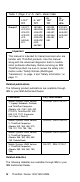
Table 1 (Page 2 of 2). 2621– Model Table Group-C I: 12.1" TFT II: 14.1" TFT 442/4FT, 4FC/4FH, 4FK/4FF, 4FS/4FP, 4FX, 542/549, 5FF 482/489, 486/4GM, 4GA/4GT, 4GC/4GH, 4GK/4GF, 4GS/4GP, 4GX, 562/569 III: 15.0" TFT IV: 13.0" HPA 492/499, 496/49M, 49A/49T, 49C/49H, 49K/49F, 592 442/4E2, 429/4EM, 4EA/4EF, 4ES/4EP, 4EX Important This manual is intended for trained servicers who are familiar with ThinkPad products.
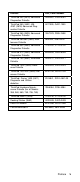
Diskette Part, Form Number ThinkPad 300 (2615) Advanced Diagnostics Diskette 33G9361, S33G-9361 ThinkPad 350, 350C, 425, 425C (2618) Advanced Diagnostics Diskette A211000, GA21-1000 ThinkPad 365 (2625) Advanced Diagnostics Diskette 76H7578, S30H-2498 ThinkPad 380/385 (2635) Maintenance Diskette 06J0333, S06J-0333 ThinkPad 500 (2603) Advanced Diagnostics Diskette 71G3702, S71G-3702 ThinkPad 510 (2604) Advanced Diagnostics Diskette 83G8095, S83G-8095 ThinkPad 700 (9552) Reference Diskette 42G20
vi ThinkPad i Series 1400/1500 HMM
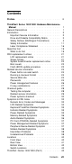
Contents Preface . . . . . . . . . . . . . . . . . . . . . iii ThinkPad i Series 1400/1500 Hardware Maintenance Manual . . . . . . . . . . . . . . . . . . . . . General Descriptions . . . . . . . . . . . . . . . Introduction . . . . . . . . . . . . . . . . . . . . Important Service Information . . . . . . . . . . Drive and Diskette Compatibility Matrix . . . . . Safety Notices (Multilingual Translations) . . . . Safety Information . . . . . . . . . . . . . . . Laser Compliance Statement . . . . . . . . .
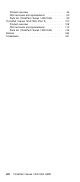
Product overview . . . . . . . . . . FRU removals and replacements . . . Parts list (ThinkPad i Series 1400/1500) ThinkPad i Series 1400/1500 (Part II) . . Product overview . . . . . . . . . . FRU removals and replacements . . . Parts list (ThinkPad i Series 1400/1500) Notices . . . . . . . . . . . . . . . . . Trademarks . . . . . . . . . . . . . . viii ThinkPad i Series 1400/1500 HMM . . . . . . . . . . . . . . . . . . . . . . . . . . . . . 44 . . 50 . . 90 . 107 . 108 . 113 . 142 . 160 .
ThinkPad i Series 1400/1500 Hardware Maintenance Manual General Descriptions This chapter includes descriptions for any ThinkPad model that has the PC-Doctor DOS diagnostics program. Some descriptions might not apply to your particular computer.
Introduction Important Service Information Important Diskette fixes are customer installable. The diskette fixes are located on the PC Company Bulletin Board Service (BBS). The direct phone line for modem connection is 919-557-0001 or tieline 255-0001. Advise customers to contact the PC Company HelpCenter at 800-772-2227 if they need assistance in obtaining or installing any diskette fixes. Customers in Canada should call IBM HelpPC at 800-565-3344 for assistance or download information.
View Configuration option) and verify that the settings are in place when service is complete. Hard Disk Drive Replacement Strategy: Always try to run a low-level format before replacing a hard disk drive. Attention: The drive startup sequence in the computer you are servicing might have been changed. Be extremely careful during write operations such as copying, saving, or formatting. Data or programs can be over-written if you select an incorrect drive.
The following table provides identification information for 5.25-inch diskette drives. Diskette Drive Identifying Mark 5.25-Inch - 360KB (External) Asterisk on bezel 5.25-Inch - 1.2MB (Internal) 1.2 on the eject button The following table provides compatibility information for 5.25-inch diskettes and 5.25-inch diskette drives. Diskette Capacity 360KB Drive 1.2MB Drive 360KB Read/Write Read/Write 1.2MB Not Compatible Read/Write Note: A 360KB diskette written to or formatted on a 1.
Safety Notice 1 Before the computer is powered-on after FRU replacement, make sure all screws, springs, or other small parts are in place and are not left loose inside the computer. Verify this by shaking the computer and listening for rattling sounds. Metallic parts or metal flakes can cause electrical shorts. Avant de remettre l'ordinateur sous tension après remplacement d'une unité en clientèle, vérifiez que tous les ressorts, vis et autres piòces sont bien en place et bien fixées.
Safety Notice 2 Some standby batteries contain a small amount of nickel and cadmium. Do not disassemble it, recharge it, throw it into fire or water, or short-circuit it. Dispose of the battery as required by local ordinances or regulations. Use only the battery in the appropriate parts listing. Use of an incorrect battery can result in ignition or explosion of the battery. Certaines batteries de secours contiennent du nickel et du cadmium.
Safety Notice 3 The battery pack contains small amounts of nickel. Do not disassemble it, throw it into fire or water, or shortcircuit it. Dispose of the battery pack as required by local ordinances or regulations. Use only the battery in the appropriate parts listing when replacing the battery pack. Use of an incorrect battery can result in ignition or explosion of the battery. La batterie contient du nickel. Ne la démontez pas, ne l'exposez ni au feu ni à l'eau. Ne la mettez pas en court-circuit.
Safety Notice 4 The lithium battery can cause a fire, explosion, or severe burn. Do not recharge it, remove its polarized connector, disassemble it, heat it above 100°C (212°F), incinerate it, or expose its cell contents to water. Dispose of the battery as required by local ordinances or regulations. Use only the battery in the appropriate parts listing. Use of an incorrect battery can result in ignition or explosion of the battery. La pile de sauvegarde contient du lithium.
Safety Notice 5 If the LCD breaks and the fluid from inside the LCD gets into your eyes or on your hands, immediately wash the affected areas with water for at least 15 minutes. Seek medical care if any symptoms from the fluid are present after washing. Si le panneau d'affichage à cristaux liquides se brise et que vous recevez dans les yeux ou sur les mains une partie du fluide, rincez-les abondamment pendant au moins quinze minutes. Consultez un médecin si des symptômes persistent après le lavage.
Safety Notice 6 To avoid shock, do not remove the plastic cover that surrounds the lower portion of the inverter card. Afin d'éviter tout risque de choc électrique, ne retirez pas le cache en plastique protégeant la partie inférieure de la carte d'alimentation. Aus Sicherheitsgründen die Kunststoffabdeckung, die den unteren Teil der Spannungswandlerplatine umgibt, nicht entfernen. Per evitare scosse elettriche, non rimuovere la copertura in plastica che avvolge la parte inferiore della scheda invertitore.
Safety Notice 8 Before removing any FRU, power-off the computer, unplug all power cords from electrical outlets, remove the battery pack, then disconnect any interconnecting cables. Avant de retirer une unitÒ rempla able en clientèle, mettez le système hors tension, débranchez tous les cordons d'alimentation des socles de prise de courant, retirez la batterie et déconnectez tous les cordons d'interface.
Before you start the machine, ensure that other service representatives and the customer's personnel are not in a hazardous position. Place removed covers and other parts in a safe place, away from all personnel, while you are servicing the machine. Keep your tool case away from walk areas so that other people will not trip over it. Do not wear loose clothing that can be trapped in the moving parts of a machine. Ensure that your sleeves are fastened or rolled up above your elbows.
– Working near power supplies – Removing or installing main units Before you start to work on the machine, unplug the power cord. If you cannot unplug it, ask the customer to power-off the wall box that supplies power to the machine and to lock the wall box in the off position. If you need to work on a machine that has exposed electrical circuits, observe the following precautions: – Ensure that another person, familiar with the power-off controls, is near you.
– Motor generators and similar units. (This practice ensures correct grounding of the units.) If an electrical accident occurs: – Use caution; do not become a victim yourself. – Switch off power. – Send another person to get medical aid. Safety Inspection Guide: The intent of this inspection guide is to assist you in identifying potentially unsafe conditions on these products.
6. Check inside the unit for any obvious unsafe conditions, such as metal filings, contamination, water or other liquids, or signs of fire or smoke damage. 7. Check for worn, frayed, or pinched cables. 8. Check that the power-supply cover fasteners (screws or rivets) have not been removed or tampered with. Handling Electrostatic Discharge-Sensitive Devices: Any computer part containing transistors or integrated circuits ( ICs) should be considered sensitive to electrostatic discharge (ESD).
Grounding Requirements: Electrical grounding of the computer is required for operator safety and correct system function. Proper grounding of the electrical outlet can be verified by a certified electrician. Laser Compliance Statement Some IBM Personal Computer models are equipped from the factory with a CD-ROM drive. CD-ROM drives are also sold separately as options. The CD-ROM drive is a laser product. The CD-ROM drive is certified in the U.S.
CAUTION: Use of controls or adjustments or performance of procedures other than those specified herein might result in hazardous radiation exposure. O uso de controles, ajustes ou desempenho de procedimentos diferentes daqueles aqui especificados pode resultar em perigosa exposição à radiação. Pour éviter tout risque d'exposition au rayon laser, respectez les consignes de réglage et d'utilisation des commandes, ainsi que les procédures décrites.
DANGER Laser radiation when open. Do not stare into the beam, do not view directly with optical instruments, and avoid direct exposure to the beam. Radiação por raio laser ao abrir. Não olhe fixo no feixe de luz, não olhe diretamente por meio de instrumentos óticos e evite exposição direta com o feixe de luz. Rayonnement laser si carter ouvert. Évitez de fixer le faisceau, de le regarder directement avec des instruments optiques, ou de vous exposer au rayon. Laserstrahlung bei geöffnetem Gerät.
Read this first Before you go to the check procedures, be sure to read this section. Important Notes Only certified trained personnel should service the computer. Read the entire FRU service procedures before replacing any FRUs. Use new nylon-coated screws when you replace FRUs. Be extremely careful during write operations such as copying, saving, or formatting. Drives in the computer that you are servicing might have been rearranged or the drive startup sequence might have been altered.
Before checking problems with the computer, determine whether the damage is covered under the warranty by referring to the following: Note for Warranty: For Warranty: During the warranty period, the customer may be responsible for repair costs if the computer damage was caused by misuse, accident, modification, unsuitable physical or operating environment, or improper maintenance by the customer.
FRU replacement notices This section contains notices for removal and replacement. Read this section carefully before replacing any FRU. LCD replacement notice The TFT LCD for the computer contains many thin-film transistors (TFTs). A small number of missing, discolored, or lighted dots (on all the time) is characteristic of TFT LCD technology, but excessive pixel problems can cause viewing concerns.
Turn an additional 180 degrees after the screw head touches the surface of the plastic part: Torque driver If you have a torque driver, refer to the "Torque" column with each step. Make sure you use the correct screw, and tighten all screws firmly to the torque shown in the table if you have a torque screwdriver. Never use a screw that you removed. Use a new one. Make sure the screws are tightened firmly.
Note: The system unit serial number is written in the label attached on bottom of the computer. Bios Levels An incorrect level of BIOS can cause false error and unnecessary FRU replacement. Use the following information to determine the current level of BIOS installed in the computer, the latest BIOS available for the computer, and where to obtain the latest level of BIOS. Current Level BIOS information. 1. Power-on the computer. 2. Press F1 at the IBM log screen to enter Setup. 3.
Related service information This section provides information about the following: “Power button as reset switch” “Running a low-level format” “Service Web site” “Passwords” “Power management features” on page 26 “Fn key combinations” on page 27 Power button as reset switch The power button acts as a reset switch when pressed for more than 4 seconds. This resets the system (regardless of the microcode status) and forces the power off.
Removing the power-on and setup passwords: Removing the power-on and setup passwords: Do the following to remove the passwords:: 1. Power off the computer. 2. Remove the battery and the AC Adapter. 3. Remove the keyboard, see "Keyboard" on page 60. 4. Change DIP switch position (Pin 6) to "Check Password Disabled", see "Switch Locations" on page 43. 5. Put back keyboard. 6. Connect the AC Adapter. 7. Power on the computer and press F1 to enter the BIOS Utility menu. 8.
14. Select None. 15. Save the changes, and exit the BIOS Utility menu. 16. Power off the computer. 17. Disconnect the AC Adapter. 18. Remove the keyboard. 19. Change DIP switch position (Pin 6) to "Check Password Enabled". 20. Put back the keyboard. Power management features Two power management modes are available in the computer system to reduce power consumption and to prolong battery life. Standby mode: When in standby mode, the fol- lowing occurs: The LCD backlight turns off.
Hibernation mode: When in hibernation mode, the following occurs: The system status, RAM, VRAM, and setup data are stored on the hard disk. The system is powered off. Events that cause the computer to enter hibernation mode: Note: These events depend on the Power buttons settings (options set to hibernation mode) in the "Advanced" page of the "Power Management Properties" screen.
Checkout guide Use the following procedure as a guide for computer problems. Note: The diagnostic tests are intended to test only IBM products. Non-IBM products, prototype cards, or modified options can give false errors and invalid system responses. 1. Obtain the failing symptoms in as much detail as possible. 2. Verify the symptoms by attempting to recreate the failure by running the diagnostic test or by repeating the same operation.
FRU, such as the flexible cable, has no problem by doing the following: a. Replace each peripheral FRU one at a time, and run the test again. b. If the peripheral FRUs have no problem, replace the main FRU itself. To see the FRU structure of each model, refer to “Product overview” on page 44. 6. To exit the test, select Quit – Exit Diag. To cancel the test, press Esc. The following table lists the options on the test menu.
DOS Shell Tech Support Form Battery Rundown View Test Log Print Log Save Log Full Erase Hard Drive Quick Erase Hard Drive Power systems checkout To verify the symptom of the power problem on the computer, do the following: 1. Power off the computer. 2. Remove the battery pack. 3. Connect the AC Adapter. 4. Check that power is supplied when you power on the computer. 5. Power off the computer. 6. Disconnect the AC Adapter and install the charged battery pack. 7.
Pin Voltage (V dc) 1 15.5V — 17.0V 2 Ground If the voltage is not correct, replace the AC Adapter. If the voltage is within the range, do the following: Replace the DC-DC & BATT board. Replace the system board. If the problems still persist, go to “Undetermined Problems” on page 38. Note: An audible noise from the AC Adapter does not always indicate a defect.
1 2 3 4 5 6 7 Terminal Signal / Voltage (V dc) 1 BT- 2 BT-SENSE 3 BT-SCLK 4 BT-SDATA 5 BT-TH 6 BT+SENSE 7 BT+ Note: Signal lines, not used in these steps, are used for communications between the system and the battery. 3. First, discharge the battery, until the voltage is less than 10.8V (LiIon) or 9.6V (NiMH). Then, charge the battery for 30 minutes. Now, check the voltage. If the voltage is still less than 10.8V (Li-Ion) or 9.6V (NiMH), replace the battery. 4.
Symptom-to-FRU Index The Symptom-to-FRU Index lists the symptoms and errors and the possible causes. The most likely cause is listed first. Note: Perform the FRU replacement or actions in the sequence shown in the FRU/Action columns. If a FRU does not solve the problem, put the original part back in the computer. Do not replace a nondefective FRU. This index can also be used to help you decide which FRUs should be available when servicing a computer.
Error Code Message FRU/Action in Sequence 072 CMOS Checksum Error 1 Enter BIOS Utility and execute "Load Setup Default Settings"; then reboot the system. 110 Incorrect Password Specified. System Halted 1 252 VPD Checksum Error Operating system not found Set SWZ1 Pin 6 (Check Password) to "0". Enter BIOS Utility and clear password. Set SWZ1 Pin 6 (Check Password) to "1". Run CE Utility. Input correct data. Boot from system diskette.
Symptom/Error FRU/Action in Sequence Unreadable LCD screen. Reseat LCD connector Check LCD inverter ID Missing pels in characters. LCD FPC ASM LCD inverter LCD System board Check LCD inverter ID LCD FPC ASM LCD inverter LCD System board Abnormal screen Wrong color displayed. LCD has extra horizontal or vertical lines displayed. Keyboard/TrackPoint-Related Symptoms Symptom/Error Keyboard (one or more keys) doesn't work. TrackPoint does not work.
Symptom/Error The system doesn't power on. The system doesn't power off. Battery can't be charged. FRU/Action in Sequence Go to “Power systems checkout” on page 30. AC Adapter Battery DC/DC & Charge board System board Go to “Power systems checkout” on page 30. Hold and press the power switch for more than 4 seconds. DC/DC & Charge board System board Go to “Power systems checkout” on page 30.
PC Card (PCMCIA)-Related Symptoms Symptom/Error System cannot detect the PC Card (PCMCIA) PCMCIA slot pin is damaged. FRU/Action in Sequence PC Card (PCMCIA) slots assembly System board PC Card (PCMCIA) slots assembly Power Management-Related Symptoms Symptom/Error The system doesn't enter hibernation mode. The system doesn't resume from hibernation mode. FRU/Action in Sequence Go to “Hibernation mode” on page 27.
Symptom/Error Printer problems. Serial or parallel port device problems. FRU/Action in Sequence Run printer self-test. Printer driver Printer cable Ensure that "Parallel Port" in the "Onboard Devices Configuration" menu of the BIOS Utility is correctly set. System board Device driver Device cable Device Ensure that "Serial Port" and "Parallel Port" in the "Onboard Devices Configuration" menu of the BIOS Utility is correctly set.
2. Check the cables, wires, and connectors for short circuits and open circuits. Visually check them for damage. If any problems are found, replace the FRU. 3. Remove or disconnect all of the following devices: Non-IBM devices Printer, external mouse & keyboard, and other external devices Battery pack Hard disk drive Diskette drive/CD-ROM drive PC Card (PCMCIA) 4. Power on the computer. 5. Determine if the problem has changed. 6.
Locations Front View 1. LCD latches 2. Keyboard Light (available on select models only) 3. LCD 4. Speakers 5. Keyboard Light switch (available on select models only) 6. Status indicators 7. CD-ROM or DVD-ROM drive 8. CD-ROM/DVD-ROM drive activity indicator 9. CD-ROM/DVD-ROM drive eject button 10. CD-ROM/DVD-ROM drive emergency eject hole 11. Battery pack 12. Media Center 13. Media Center previous track/chapter button 14. Media Center next track/chapter button 15. Volume control 16.
2 1 26 1 25 4 24 3 23 22 4 21 5 6 20 11 12 13 14 7 8 15 16 10 17 18 19 9 Note: 15" LCD has different locations of speakers, microphone and status indicator. The speakers are located in the back of LCD. Microphone and status indicator are moved to the main unit. Rear View 17 16 15 1 2 14 3 13 4 5 6 7 8 9 10 11 12 1.
2. Mouse/keyboard (PS/2) connector 3. Telephone connector 4. Serial connector 5. Parallel connector 6. Security keyhole 7. Universal serial bus (USB) connector 8. External monitor connector 9. TV-out (S-video) jack 10. PC Card slots 11. PC Card eject buttons 12. Line-out/headphone jack 13. Line-in jack 14. Microphone-in jack 15. Diskette drive 16. Diskette-drive-activity indicator 17. Diskette eject button Bottom View 2 3 4 1. Battery-pack latch 2. Memory slot door 3. Modem card compartment 4.
Switch Locations There are two switches found on the system board. Refer to the figure below on how to set these switches. Boot Block Disabled Boot Block Enabled Pin 3 Pin 4 Pin 5 English Japanese German Pin 6 Check Password Enabled Check Password Disabled ThinkPad i Series 1400/1500 (Part I) This section applies to the models in Group-A and B. (See the 2621 model table on page iii.
Product overview The following shows an overview of the system features. Note: The table below applies to the models in Group-A (See the 2621 model table on page iii.) Feature Description Processor Intel** Celeron** processor 400, 433 or 466 MHz Bus architecture PCI System memory 2 DIMM slots, no memory on system board 32 MB, 64 MB, and 128 MB DIMM card Maximum frequency: 66 MHz CMOS RAM 114 bytes + 4 Kbytes Video 12.1–inch, 16M colors, 800x600 pixel TFT SVGA color LCD 13.
Feature Description AC Adapter 56–Watt type Note: The table below applies to the models in Group-B (See the 2621 model table on page iii.) Feature Description Processor Intel** Celeron** processor 466 MHz Bus architecture PCI System memory 2 DIMM slots, no memory on system board 32 MB, 64 MB, and 128 MB DIMM card Maximum frequency: 66 MHz CMOS RAM 114 bytes + 4 Kbytes Video 12.1–inch, 16M colors, 800x600 pixel TFT SVGA color LCD 13.0–inch, 16M colors, 800x600 pixel HPA SVGA color LCD —or— 14.
Feature Description AC Adapter 56–Watt type Status indicators: The system-status indicators on the computer show the current status of your computer by their on or off states and colors (green and orange). Each indicator is identified with a symbol.
Symbol Color Meaning (1) Battery status Green Enough battery power remains for operation. Blinking orange The battery pack needs to be charged Orange The battery pack is being charged. Green The computer is in standby mode Blinking green The computer is entering or resuming from hibernation mode. (3) Drive in use Orange (some will be Green) Data is being read from or written to the hard disk, floppy drive, or data is being read from the CD-ROM drive.
FRU tests: The following table shows the applicable test for each FRU using PC-Doctor. FRU System board Applicable test 1. CPU/Coprocessor (Diagnostics) 2. System board (Diagnostics) Power LCD unit Battery (Diagnostics) 1. Video Adapter (Diagnostics) 2. Video (Interactive Tests) Modem 1. Make sure the modem set up correctly. 2.
FRU Memory Applicable test 1. If a DIMM is installed, remove it and run Memory Test-Quick (Diagnostics) 2. If the problem does not recur, replace the DIMM and run the test again. 3. If the test does not detect the error, run Memory Test-Full (Diagnostics) Fan 1. Start Windows 98 and check the air turbulence at the louver at the rear of the computer. 2. Run the fan test in Other Devices (Diagnostics).
FRU removals and replacements This section contains information about removals and replacements. Do not damage any parts. Only certified and trained personnel should service the computer. The arrows in this section show the direction of movement to remove a FRU, or to turn a screw to release the FRU. The arrows are marked in numeric order, in square callout, to show the correct sequence of removal. Any FRUs that must be removed before removing the failing FRU are listed at the top of the page.
An electrostatic discharge (ESD) strap (P/N: 6405959) must be used to establish personal grounding. Battery assembly 2 1 3 Note: When install a new battery pack, push the battery in and lock it. No need to repeat step 1 and 2. Warning Battery packs are capable of delivering high currents for a significant amount of time. Do not short the battery terminals.
2 Step Size (Quantity) Color Torque 1 M2.5 x 6L (2) Black 3.
6 Note: The FPC is connected to the system board by the other end. When removing the CD player panel and CD player control board, release the FPC with caution. Hard disk drive assembly “Battery assembly” on page 51 “CD player panel and CD player control board” on page 51 Warning Do not drop or apply any shock to the hard disk drive. The hard disk drive is sensitive to physical shock. Incorrect handling can cause damage and permanent loss of data on the drive.
Hard disk drive kitting pack “Battery assembly” on page 51 “CD player panel and CD player control board” on page 51 “Hard disk drive assembly” on page 53 1 2 Step Size (Quantity) Color Torque 1 M3 x 4L (2) Silver 3.
Note: The screw does not separate from the memory cover. To install the memory card: With the notched end of the memory card toward the right side of the socket, insert the memory card, at an angle of approximately 20°, into the socket; then press it firmly. Pivot the memory card until it snaps into place. Modem cover and modem card “Battery assembly” on page 51 2 1 Note: The screw does not separate from the modem cover. To remove the modem card: 1. Disconnect the modem cable. 2.
3 1 2 When reinserting the card, reverse the procedures above.
Optional customerized sheet 2 3 Power button 4 5 Step Size (Quantity) Color Torque 1 M2 x 4L (2) Silver 1.
Step Size (Quantity) Color Torque 3 M2.5 x 3.5L (2) Black 3.
Notes: 1. Adjust the LCD module to the widest angle. Be careful not to scratch the surface of the middle cover. 2. Turn the middle cover and launch key assembly upside down when removing the FFC. 10 CAUTION: There is a FFC connected to the middle cover. When removing the middle cover, release the FFC with caution.
Keyboard “Battery assembly” on page 51 “Middle cover and launch key assembly” on page 56 1 2 3 Large green FPC 7 4 Small green FPC 5 6 Yellow FPC Note: Make sure the FPC finger side is facing outwards, when inserted.
Notes: 1. When replacing the keyboard, make sure that the 3 cables are clean and insert them directly into the connectors, making sure they make contact with the bottom of the connector. Now press down on the latch of the connector to secure. 2. If the cables do not touch the bottom of the connector, the keyboard function will be rendered useless. 3. The cables of the keyboard are fragile and could be damaged. Be careful when pulling out the cables.
4 CD-ROM/DVD-ROM assembly “Battery assembly” on page 51 “Middle cover and launch key assembly” on page 56 “Keyboard” on page 60 “Upper heat sink” on page 61 1 CAUTION: When the CD-ROM/DVD-ROM assembly is removed, the machine is unstable.
2 1 Step Size (Quantity) Color Torque 1 M2 x 3L (4) Silver 1.8 kgf-cm 4 3 Caution Do not disassemble the CD-ROM; there are no user adjustments or serviceable parts inside. The use of controls, adjustments or performing procedures other than those specified may result in hazardous radiation exposure. The CD-ROM is a sensitive electronic device, handling should be cautious. Do not apply any extra force to the CD-ROM drive when removing it.
1 2 Step Size (Quantity) Color Torque 1 M2 x 4L (4) Silver with washer head 1.
3 Note: Before removing and replacing the PCMCIA holder, make sure that the PCMCIA cards are removed. CAUTION: When removing the PCMCIA holder, pull them up at an angle. It cannot be removed when pulled straight up. LCD assembly “Battery assembly” on page 51 “Middle cover and launch key assembly” on page 56 “Keyboard” on page 60 1 Step Size (Quantity) Color Torque 1 M2.5 x 6L (2) Black 3.
3 4 2 Step Size (Quantity) Color Torque 2 M2 x 12L (2) Silver 1.6 kgf-cm 4 M2.5 x 6L (1) Black 3.
Safety Notice 4 Translation in "Safety Notices: Multilingual Translations" section: The backup battery is a lithium battery and can cause a fire, an explosion, or severe burns. Do not recharge it, remove its polarized connector, disassemble it, heat it above 100°C (212°F), incinerate it, or expose its cell contents to water. Dispose of the battery as required by local ordinances or regulations. Use of an incorrect battery can result in ignition or explosion of the battery.
3 4 5 Step Size (Quantity) Color Torque 1 M2.5 x 6L (4) Black 3.2 kgf-cm 2 M2.5 x 3.5L (2) Black 3.
7 6 Fragile CAUTION: The upper cover has several latches. When removing the upper cover from the bottom cover, gently release these latches, then raise the side of the uppoer cover facing the palm rest to remove it. Be careful not to break the latches.
Step Size (Quantity) Color Torque 1 M2.5 x 3.5L (3) Black 2.0 kgf-cm 2 M2 x 4L (1) Silver 1.
2 3 1 Step Size (Quantity) Color Torque 2 M2.5 x 3.5L (2) Black 3.2 kgf-cm DC-DC charger board “Battery assembly” on page 51 “Middle cover and launch key assembly” on page 56 “Keyboard” on page 60 “Upper heat sink” on page 61 “CD-ROM/DVD-ROM assembly” on page 62 “LCD assembly” on page 65 “Keyboard bezel” on page 67 2 1 Step Size (Quantity) Color Torque 1 M2.5 x 3.5L (2) Black 3.
System board “Battery assembly” on page 51 “Middle cover and launch key assembly” on page 56 “Keyboard” on page 60 “Upper heat sink” on page 61 “LCD assembly” on page 65 “Keyboard bezel” on page 67 “Fan assembly” on page 70 “DC-DC charger board” on page 71 1 2 3 Step Size (Quantity) Color Torque 1 M2.5 x 3.5L(3) Black 3.2 kgf-cm 4 Notes: 1.
Bottom case “Battery assembly” on page 51 “Middle cover and launch key assembly” on page 56 “Keyboard” on page 60 “Upper heat sink” on page 61 “CD-ROM/DVD-ROM assembly” on page 62 “LCD assembly” on page 65 “Keyboard bezel” on page 67 “System board” on page 72 LCD bezel assembly (12.
2 3 2 Step Size (Quantity) Color Torque 2 M2.5 x 10L(2) Black 1.6 kgf-cm 3 M2.5 x 6L(1) Black 1.6 kgf-cm 9 7 4 8 5 6 Note: When removing the LCD, take note of the following: Be careful not to scratch the LCD cover when removing the screw covers. The LCD front cover has several latches. Release these latches; then remove the LCD cover. Be careful not to break these latches. Gently push the two hooks outward to remove the LCD front cover. LCD bezel assembly (13.
1 2 3 2 Step Size (Quantity) Color Torque 2 M2.5 x 10L(2) Black 3.2 kgf-cm 3 M2.5 x 6L(1) Black 3.2 kgf-cm 10 8 4 9 7 6 5 Note: When removing the LCD, take note of the following: Be careful not to scratch the LCD cover when removing the screw covers. The LCD front cover has several latches. Release these latches; then remove the LCD cover. Be careful not to break these latches.
Gently push the two hooks outward to remove the LCD front cover. LCD bezel assembly (14.1") “Battery assembly” on page 51 “Middle cover and launch key assembly” on page 56 “Keyboard” on page 60 “LCD assembly” on page 65 1 2 3 2 Step Size (Quantity) Color Torque 2 M2.5 x 10L(2) Black 3.2 kgf-cm 3 M2.5 x 6L(1) Black 3.
10 8 4 9 7 6 5 Note: When removing the LCD, take note of the following: Be careful not to scratch the LCD cover when removing the screw covers. The LCD front cover has several latches. Release these latches; then remove the LCD cover. Be careful not to break these latches. Gently push the two hooks outward to remove the LCD front cover. LED board (12.
2 3 Left speaker Microphone 5 Right speaker 6 4 LED board (13.0") “Battery assembly” on page 51 “Middle cover and launch key assembly” on page 56 “Keyboard” on page 60 “LCD assembly” on page 65 “LCD bezel assembly (13.0")” on page 74 1 Step Size (Quantity) Color Torque 1 M2 x 4L(2) Silver 1.
2 3 Left speaker Microphone 5 Right speaker 6 4 LED board (14.1") “Battery assembly” on page 51 “Middle cover and launch key assembly” on page 56 “Keyboard” on page 60 “LCD assembly” on page 65 “LCD bezel assembly (14.1")” on page 76 1 Step Size (Quantity) Color Torque 1 M2 x 4L(2) Silver 1.
2 3 Left speaker Microphone Right speaker 5 Light 6 4 LCD inverter (12.1") “Battery assembly” on page 51 “Middle cover and launch key assembly” on page 56 “Keyboard” on page 60 “LCD assembly” on page 65 “LCD bezel assembly (12.1")” on page 73 1 Step Size (Quantity) Color Torque 1 M2 x 4L(2) Silver 1.6 kgf-cm M3 x 5L(1) Silver 3.
2 3 4 LCD inverter (13.0") “Battery assembly” on page 51 “Middle cover and launch key assembly” on page 56 “Keyboard” on page 60 “LCD assembly” on page 65 “LCD bezel assembly (13.0")” on page 74 1 2 Step Size (Quantity) Color Torque 1 M2 x 4L(2) Silver 1.6 kgf-cm 4 3 LCD inverter (14.1") “Battery assembly” on page 51 “Middle cover and launch key assembly” on page 56 “Keyboard” on page 60 “LCD assembly” on page 65 “LCD bezel assembly (14.
1 2 Step Size (Quantity) Color Torque 1 M2 x 4L(2) Silver 1.6 kgf-cm 3 4 Cable assembly of microphone (12.1") “Battery assembly” on page 51 “Middle cover and launch key assembly” on page 56 “Keyboard” on page 60 “LCD assembly” on page 65 “LCD bezel assembly (12.1")” on page 73 “LED board (12.1")” on page 77 Cable assembly of microphone (13.
Cable assembly of microphone (14.1") “Battery assembly” on page 51 “Middle cover and launch key assembly” on page 56 “Keyboard” on page 60 “LCD assembly” on page 65 “LCD bezel assembly (14.1")” on page 76 “LED board (14.1")” on page 79 LCD bracket hinge assembly, speaker assembly and LCD rear cover assembly (12.1") “Battery assembly” on page 51 “Middle cover and launch key assembly” on page 56 “Keyboard” on page 60 “LCD assembly” on page 65 “LCD bezel assembly (12.
1 Step Size (Quantity) Color Torque 1 M3 x 5L(3) Silver 3.
3 2 Step Size (Quantity) Color Torque 2 M2.5 x 6L(3) Black 3.2 kgf-cm 5 4 Step Size (Quantity) Color Torque 4 M2.5 x 6L(2) Black 3.2 kgf-cm LCD bracket hinge assembly, speaker assembly and LCD rear cover assembly (13.0") “Battery assembly” on page 51 “Middle cover and launch key assembly” on page 56 “Keyboard” on page 60 “LCD assembly” on page 65 “LCD bezel assembly (13.
“LED board (13.0")” on page 78 “LCD inverter (13.0")” on page 81 “Cable assembly of microphone (13.0")” on page 82 1 Step Size (Quantity) Color Torque 1 M2.5 x 6L(7) Black 3.2 kgf-cm LCD bracket hinge assembly, speaker assembly, keyboard light, and LCD rear cover assembly (14.1") “Battery assembly” on page 51 “Middle cover and launch key assembly” on page 56 “Keyboard” on page 60 “LCD assembly” on page 65 “LCD bezel assembly (14.1")” on page 76 “LED board (14.
“Cable assembly of microphone (14.1")” on page 83 1 2 3 4 Step Size (Quantity) Color Torque 1 M2.5 x 6L(2) Black 3.2 kgf-cm 2 M2 x 4L(1) Silver 1.6 kgf-cm 3 M2 x 3L(4) Silver 1.
LCD FPC assembly (12.1") “Battery assembly” on page 51 “Middle cover and launch key assembly” on page 56 “Keyboard” on page 60 “LCD assembly” on page 65 “LCD bezel assembly (12.1")” on page 73 “LED board (12.1")” on page 77 “LCD inverter (12.1")” on page 80 “Cable assembly of microphone (12.1")” on page 82 “LCD bracket hinge assembly, speaker assembly and LCD rear cover assembly (12.1")” on page 83 LCD FPC assembly (13.
“LCD bezel assembly (14.1")” on page 76 “LED board (14.1")” on page 79 “LCD inverter (14.1")” on page 81 “Cable assembly of microphone (14.1")” on page 83 “LCD bracket hinge assembly, speaker assembly, keyboard light, and LCD rear cover assembly (14.
Parts list (ThinkPad i Series 1400/1500) 1 14 2 15 3 16 4 17 5 2-a 18 6 19 20 7 21 22 8 9 10 11 12 13 Note: The table below applies to the models in Group-A (See the 2621 model table on page iii.) No. Description FRU No. 1 Middle Cover & Launch Key ASM 14.
No. Description FRU No. Middle Cover & Launch Key ASM 14.1" (for Japan) 08K6054 Middle Cover & Launch Key ASM 12.1"/13.0" 08K5869 Middle Cover & Launch Key ASM 12.1"/13.
No. Description FRU No. HDD Module Assy. 8.1 GB (IBM) 05K9176 Kitting, HDD (HDD adapter bracket SCR) 08K5861 20 RTC Battery 11J8591 21 FPC Cable Group (FPCs of CD-ROM, FDD, EZ Launch, CD-Play) 27L0498 22 Battery Assy (LiIon) 9 Cells (Panasonic) 02K6647 Battery Assy (NiMH) 8 Cells (Panasonic) 02K6630 LEG (R/L) 08K5870 Miscellaneous Kit 08K6604 9-a Right Hinge Cap 12.1"/13.0" Right Hinge Cap 14.
No. Description FRU No. Miscellaneous Kit (for Japan) 08K6592 Right Hinge Cap 12.1"/13.0" 12.1" LCD FPC Holder 12.1" Top Bracket * 2 Right Hinge Cap 14.1" Rubber Foot * 4 PCMCIA Screw Cover * 4 Modem Cover Mylar Film CD-Player Panel Mylar Screw Cushion for LCD Bezel * 2 (Japan model) Screw Cap for LCD Bezel (Japan model) Screw Mylar for Rear Cover * 4 (Japan model) RJ11 Cable 13.0" Top Bracket * 2 Battery Latch Knob Keyboard Light Switch Launch Key Panel Screw Kit 08K5877 WAFER MYLO M2.5*3.
No. Description FRU No.
No. Description FRU No. CD Control Card 08K3405 Miscellaneous Kit 08K6604 Right Hinge Cap 12.1"/13.0" Right Hinge Cap 14.1" Rubber Foot * 4 PCMCIA Screw Cover * 4 Modem Cover Mylar Film CD-Player Panel Mylar Screw Cushion for LCD Bezel * 2 Screw Cap for LCD Bezel Screw Mylar for Rear Cover * 4 12.1" LCD FPC Holder RJ11 Cable 12.1" Top Bracket * 2 13.0" Top Bracket * 2 Battery Latch Knob Keyboard Light Switch Launch Key Panel Miscellaneous Kit (for Japan) 08K6592 Right Hinge Cap 12.1"/13.0" 12.
No. Description FRU No. Screw Kit 08K5877 WAFER MYLO M2.5*3.5LB-ZN Black PAN NYLOK M2.5*6LB-ZN Black PAN NYLOK M2.
LCD FRU 12.1-inch SVGA TFT 1 2 3 9 4 10 3 5 4 5 6 11 7 8 Note: The table below applies to the models in Group-A (See the 2621 model table on page iii.) No. Description FRU No. 1 LCD BEZEL ASM 12.1" 08K5849 2 12.1" TFT LCD 08K5844 3 LCD Bracket-Hinge 12.1" (R,L) 08K5850 4 Misc. 12.
No. Description FRU No. 6 12.1" LCD FPC Assy. 27L0494 7 Cable Asm. of Microphone & Keyboard LED Light 27L0497 Cable Asm. of Microphone & Keyboard LED Light (for Japan) 27L0511 8 LCD Rear Cover ASM 12.1" TFT 08K5848 9 LCD Inverter 12.1" 10L1380 10 Misc. Right Hinge Cap 12.1"/13.0" (for worldwide) 08K6604 Misc. Right Hinge Cap 12.1"/13.
13.0-inch SVGA HPA 1 2 3 2 4 3 10 4 5 6 7 8 11 9 Note: The table below applies to the models in Group-A and B (See the 2621 model table on page iii.) No. Description FRU No. 1 LCD BEZEL ASM 13.0" 08K5853 LCD BEZEL ASM 13.0" (for Japan) 08K6051 2 Misc. 13.0" Top Bracket 08K5878 3 Speaker Module (R,L) 08K6374 4 LCD Bracket-Hinge 13.0" (R,L) 08K5854 5 13.0" HPA LCD 05K9596 6 13.0" LCD FPC Assy. 27L0495 13.0" LCD FPC Assy.
No. Description FRU No. 7 LCD Inverter 12.1"/13.0" 10L1380 8 Cable Asm. of Microphone & Keyboard LED Light 27L0497 Cable Asm. of Microphone & Keyboard LED Light (for Japan) 27L0511 LCD Rear Cover ASM 13.0" HPA 08K5852 LCD Rear Cover ASM 13.0" HPA (with logo kit) (for Japan) 08K6048 Misc. Right Hinge Cap 12.1"/13.0" (for worldwide) 08K6604 Misc. Right Hinge Cap 12.1"/13.
14.1" XGA TFT 1 2 3 2 4 9 4 5 6 7 10 7 8 Note: The table below applies to the models in Group-A (See the 2621 model table on page iii.) No. Description FRU No. 1 LCD BEZEL ASM 14.1" 08K5856 LCD BEZEL ASM 14.1" (for Japan) 08K6050 2 LCD Bracket-Hinge 14.1" (R,L) 08K5857 3 14.1" TFT LCD (LG) 05K9591 14.1" TFT LCD (Samsung) 05K9498 4 Speaker Module (R,L) 08K6374 5 14.1" LCD FPC Assy. 27L0496 14.1" LCD FPC Assy. (for Japan) 27L0509 LCD Inverter 14.
No. Description FRU No. 7 Cable ASM of Microphone & Keyboard LED Light 27L0497 Cable ASM of Microphone & Keyboard LED Light (for Japan) 27L0511 LCD Rear Cover ASM 14.1" TFT 08K5855 LCD Rear Cover ASM 14.1" TFT (for Japan) 08K6047 Misc. Right Hinge Cap 14.1" (for worldwide) 08K6604 Misc. Right Hinge Cap 14.1" (for Japan) 08K6592 LED BD 10L1443 LG/IBM Logo Kit 08K5860 8 9 10 Note: The table below applies to the models in Group-B (See the 2621 model table on page iii.) No.
No. 9 10 Description FRU No. LCD Rear Cover ASM 14.1" TFT (NEC LCD) 08K6275 LCD Rear Cover ASM 14.1" TFT (NEC LCD) (for Japan model) 08K6385 Misc. Right Hinge Cap 14.1" (for worldwide) 08K6604 Misc. Right Hinge Cap 14.1" (for Japan) 08K6592 LED BD 10L1443 LG/IBM Logo Kit 08K5860 Keyboard Description Vendor FRU No.
Description Vendor FRU No. Keyboard JAPANESE ALPS 02K5070 Keyboard TRAD. CHINESE ALPS 02K5071 Keyboard ITALIAN ALPS 02K5072 Keyboard SPANISH ALPS 02K5073 Keyboard SWISS ALPS 02K5074 Keyboard PORTUGUESE ALPS 02K5075 Keyboard BELGIAN ALPS 02K5076 Keyboard LA SPANISH ALPS 02K5094 Common parts list Tools Description FRU No.
Description FRU No.
AC adapter Description FRU No. AC Adapter 2-pin (Delta) 02K6548 AC Adapter 2-pin (Sanken) 02K6554 AC Adapter 3-pin (Delta) 02K6550 AC Adapter 3-pin (Sanken) 02K6555 Power cords: IBM power cords for a specific country are usually available only in that country. For 2–pin power cords: IBM power cord part number Used in these countries or regions 13H5273 Japan For 3–pin power cords: Note: The grounded adapter is required for full MPRII compliance.
IBM power cord part number Used in these countries or regions 76H3524 Abu Dhabi, Albania, Antigua, Bahrain, Brunei, Dubai, Fiji, Hong Kong, India, Ireland, Kenya, Kuwait, Malaysia, Nigeria, Oman, Qatar, Singapore, United Kingdom 76H3528 Liechtenstein, Switzerland 76H3530 Chile, Ethiopia, Italy, Libya 76H3532 Israel 76H3535 Korea ThinkPad i Series 1400/1500 (Part II) This section applies to the models in Group-C. (See the 2621 model table on page iii.
Product overview The following shows an overview of the system features. Feature Description Processor Intel** Pentium** III processor 500 MHz —or— Intel** Celeron** processor 500 MHz Bus architecture PCI & AGP System memory 2 DIMM slots, no memory on system board 32 MB, 64 MB, and 128 MB DIMM card Maximum frequency: 100 MHz CMOS RAM 114 bytes + 4 Kbytes Video 12.1–inch, 18 bit colors, 800x600 pixel TFT SVGA color LCD 13.0–inch, 16 bit colors, 800x600 pixel HPA SVGA color LCD —or— 14.
Feature Description I/O ports External monitor Speaker-out Line-in Microphone-in DC-in Mouse/keyboard Parallel Serial USB Telephone (RJ11)/Modem TV-out (S-video) AC Adapter 56–Watt type Status indicators: The system-status indicators on the computer show the current status of your computer by their on or off states and colors (green and orange). Each indicator is identified with a symbol.
2 1 Symbol Color Meaning (1) Battery status Green Enough battery power remains for operation. Blinking orange The battery pack needs to be charged Orange The battery pack is being charged. Green The computer is in standby mode Blinking green The computer is entering or resuming from hibernation mode. (3) Drive in use Green Data is being read from or written to the hard disk, floppy drive, or data is being read from the CD-ROM drive.
Symbol Color Meaning (5) Caps lock Green Caps Lock mode is enabled. All alphabetic characters (A-Z) are entered in capital letters without the Shift key being pressed. You enable or disable the Caps Lock mode by pressing the Caps Lock key. (6) Scroll lock Green Scroll Lock mode is enabled. The Arrow keys can be used as screen-scroll function keys. The cursor cannot be moved with the Arrow keys. Not all application programs support this function.
FRU Applicable test TrackPont or Pointing device If the TrackPoint does not work, see if an external PS/2 mouse is connected to the mouse/keyboard connector and remove it. The TrackPoint is automatically disabled if an external PS/2 mouse is attached. Check also if the TrackPoint driver is correctly installed by accessing Windows Device Manager via the System icon in the Control Panel. After you use the TrackPoint, the pointer drifts on the screen for a short time.
FRU removals and replacements This section contains information about removals and replacements of model types in Group-C III (15.0" TFT). For other model types in Group-C, please refer to Part I for removals and replacements. Do not damage any parts. Only certified and trained personnel should service the computer. The arrows in this section show the direction of movement to remove a FRU, or to turn a screw to release the FRU.
grounding by touching a ground point with one hand before touching these units. An electrostatic discharge (ESD) strap (P/N: 6405959) must be used to establish personal grounding. Battery assembly 2 1 3 Note: When install a new battery pack, push the battery in and lock it. No need to repeat step 1 and 2. Warning Battery packs are capable of delivering high currents for a significant amount of time. Do not short the battery terminals.
CD player panel and CD player control board 1 2 Step Size (Quantity) Color Torque 1 M2.5 x 6L (2) Black 3.
4 3 5 6 Note: The FPC is connected to the system board by the other end. When removing the CD player panel and CD player control board, release the FPC with caution.
Warning Do not drop or apply any shock to the hard disk drive. The hard disk drive is sensitive to physical shock. Incorrect handling can cause damage and permanent loss of data on the drive. Before removing the drive, have the user make a backup copy of all the information on the drive if possible. Never remove the drive while the system is operating or is in suspend mode.
Step Size (Quantity) Color Torque 1 M3 x 4L (2) Silver 3.2 kgf-cm Memory cover and memory card “Battery assembly” on page 114 2 Memory cover 1 Note: The screw does not separate from the memory cover. To install the memory card: With the notched end of the memory card toward the right side of the socket, insert the memory card, at an angle of approximately 20°, into the socket; then press it firmly. Pivot the memory card until it snaps into place.
Modem cover and modem card “Battery assembly” on page 114 2 1 Note: The screw does not separate from the modem cover. To remove the modem card: 1. Disconnect the modem cable. 2. Press the release latches on both sides of the modem board. 3. Pull out the modem card. 3 2 1 When reinserting the card, reverse the procedures above.
Launch key assembly “Battery assembly” on page 114 1 Optional customerized sheet 2 3 120 ThinkPad i Series 1400/1500 HMM
Power button 4 5 Step Size (Quantity) Color Torque 5 M2 x 4L (2) Silver 1.6 kgf-cm Notes: 1. Adjust the LCD module to the widest angle. Be careful not to scratch the surface of the middle cover. 2. Turn the middle cover and launch key assembly upside down when removing the FFC.
CAUTION: There is a FFC connected to the middle cover. When removing the middle cover, release the FFC with caution. 7 Left hinge cap “Battery assembly” on page 114 “Launch key assembly” on page 120 1 Step Size (Quantity) Color Torque 1 M2.5 x 3.5L (2) Black 3.
Keyboard “Battery assembly” on page 114 “Launch key assembly” on page 120 “Left hinge cap” 1 2 3 Large green FPC 7 4 Small green FPC 5 6 Yellow FPC Note: Make sure the FPC finger side is facing outwards, when inserted.
Notes: 1. When replacing the keyboard, make sure that the 3 cables are clean and insert them directly into the connectors, making sure they make contact with the bottom of the connector. Now press down on the latch of the connector to secure. 2. If the cables do not touch the bottom of the connector, the keyboard function will be rendered useless. 3. The cables of the keyboard are fragile and could be damaged. Be careful when pulling out the cables.
CD-ROM/DVD-ROM assembly “Battery assembly” on page 114 “Launch key assembly” on page 120 “Left hinge cap” on page 122 “Keyboard” on page 123 “Upper heat sink” on page 124 1 CAUTION: When the CD-ROM/DVD-ROM assembly is removed, the machine is unstable.
4 3 Caution Do not disassemble the CD-ROM; there are no user adjustments or serviceable parts inside. The use of controls, adjustments or performing procedures other than those specified may result in hazardous radiation exposure. The CD-ROM is a sensitive electronic device, handling should be cautious. Do not apply any extra force to the CD-ROM drive when removing it. Step Size (Quantity) Color Torque 1 M2 x 3L (2) Silver 1.
1 2 Step Size (Quantity) Color Torque 1 M2 x 4L (4) Silver with washer head 1.
3 4 Note: Before removing and replacing the PCMCIA holder, make sure that the PCMCIA cards are removed and the eject levers are sticking out. CAUTION: When removing the PCMCIA holder, pull them up at an angle. It cannot be removed when pulled straight up. LCD assembly “Battery assembly” on page 114 “Launch key assembly” on page 120 “Left hinge cap” on page 122 “Keyboard” on page 123 1 Step Size (Quantity) Color Torque 1 M2.5 x 6L (2) Black 3.
4 3 2 5 6 Step Size (Quantity) Color Torque 6 M2 x 12L (2) Silver 1.6 kgf-cm 9 8 7 Step Size (Quantity) Color Torque 7 M2.5 x 6L (1) Black 3.
LED board assembly and Cable assembly of microphone “Battery assembly” on page 114 “Launch key assembly” on page 120 “Left hinge cap” on page 122 “Keyboard” on page 123 “LCD assembly” on page 128 1 Step Size (Quantity) Color Torque 1 M2 x 4L(2) Silver 1.
Safety Notice 4 Translation in "Safety Notices: Multilingual Translations" section: The backup battery is a lithium battery and can cause a fire, an explosion, or severe burns. Do not recharge it, remove its polarized connector, disassemble it, heat it above 100°C (212°F), incinerate it, or expose its cell contents to water. Dispose of the battery as required by local ordinances or regulations. Use of an incorrect battery can result in ignition or explosion of the battery.
2 Memory cover 1 3 132 ThinkPad i Series 1400/1500 HMM
4 5 Step Size (Quantity) Color Torque 1 M2.5 x 6L (4) Black 3.2 kgf-cm 2 M2.5 x 3.5L (2) Black 3.2 kgf-cm 6 7 CAUTION: The upper cover has several latches. When removing the upper cover from the bottom cover, gently release these latches, then raise the side of the uppoer cover facing the palm rest to remove it. Be careful not to break the latches.
Diskette drive assembly “Battery assembly” on page 114 “Launch key assembly” on page 120 “Left hinge cap” on page 122 “Keyboard” on page 123 “Upper heat sink” on page 124 “CD-ROM/DVD-ROM assembly” on page 125 “LCD assembly” on page 128 “LED board assembly and Cable assembly of microphone” on page 130 “Keyboard bezel” on page 131 1 1 2 1 Step Size (Quantity) Color Torque 1 M2.5 x 3.5L (3) Black 2.0 kgf-cm 2 M2 x 4L (1) Silver 1.
3 Fan assembly “Battery assembly” on page 114 “Launch key assembly” on page 120 “Left hinge cap” on page 122 “Keyboard” on page 123 “Upper heat sink” on page 124 “LCD assembly” on page 128 “LED board assembly and Cable assembly of microphone” on page 130 “Keyboard bezel” on page 131 2 3 1 Step Size (Quantity) Color Torque 2 M2.5 x 3.5L (2) Black 3.
“LCD assembly” on page 128 “LED board assembly and Cable assembly of microphone” on page 130 “Keyboard bezel” on page 131 “Fan assembly” on page 135 1 2 2 3 Step Size (Quantity) Color Torque 1 M2.5 x 3.5L (2) Black 3.2 kgf-cm 2 M2.5 x 3.5L (3) Black 3.
6 7 Notes: 1. When removing the system board from the bottom cover, gently raise the side of the system board facing the rear I/O ports; then pull out the system board. 2. When replacing the system board, align the power switch and power actuator. Make sure that the power switch operates correctly before securing the screws.
LCD bezel assembly (15.0") “Battery assembly” on page 114 “Launch key assembly” on page 120 “Left hinge cap” on page 122 “Keyboard” on page 123 “LCD assembly” on page 128 1 Step Size (Quantity) Color Torque 1 M2.5 x 4L(1) Silver 1.6 kgf-cm 8 6 5 2 7 4 3 Note: When removing the LCD, take note of the following: 138 Be careful not to scratch the LCD cover when removing the screw covers.
The LCD front cover has several latches. Release these latches; then remove the LCD cover. Be careful not to break these latches. Gently push the two hooks outward to remove the LCD front cover. LCD inverter (15.0") “Battery assembly” on page 114 “Launch key assembly” on page 120 “Left hinge cap” on page 122 “Keyboard” on page 123 “LCD assembly” on page 128 “LCD bezel assembly (15.0")” on page 138 1 Step Size (Quantity) Color Torque 1 M2 x 4L(2) Silver 1.
LCD bracket hinge assembly (15.0") “Battery assembly” on page 114 “Launch key assembly” on page 120 “Left hinge cap” on page 122 “Keyboard” on page 123 “LCD assembly” on page 128 “LCD bezel assembly (15.0")” on page 138 “LCD inverter (15.0")” on page 139 1 2 5 3 2 4 Step Size (Quantity) Color Torque 1 M2.5 x 4L(3) Silver 1.6 kgf-cm 2 M2.5 x 6L(2) Black 3.2 kgf-cm 6 6 7 Step Size (Quantity) Color Torque 6 M2 x 3L(6) Silver 1.6 kgf-cm LCD FPC assembly (15.
“LCD inverter (15.0")” on page 139 “LCD bracket hinge assembly (15.0")” on page 140 1 2 Speaker assembly (15.0") “Battery assembly” on page 114 “Launch key assembly” on page 120 “Left hinge cap” on page 122 “Keyboard” on page 123 “LCD assembly” on page 128 “LCD bezel assembly (15.0")” on page 138 “LCD inverter (15.0")” on page 139 “LCD bracket hinge assembly (15.0")” on page 140 1 2 1 1 Step Size (Quantity) Color Torque 1 M2 x 4L(3) Silver 1.
Parts list (ThinkPad i Series 1400/1500) 1 14 2 15 3 16 4 17 5 2-a 18 6 19 20 7 21 22 8 9 10 11 12 13 Note: The table below applies to the models in Group-C I, II, and IV. (See the 2621 model table on page iii.) No. Description FRU No. 1 Middle Cover & Launch Key ASM 14.
No. Description FRU No. Middle Cover & Launch Key ASM 14.1" (for Japan) 08K6054 Middle Cover & Launch Key ASM 12.1"/13.0" 08K5869 Middle Cover & Launch Key ASM 12.1"/13.
No. Description FRU No. Kitting, HDD (HDD adapter, HDD bracket (for 9.5mm HDD), HDD bracket (for 12.5mm HDD), screw x 2)) 08K5861 20 RTC Battery 11J8591 21 FPC Cable Group 27L0498 22 Battery Assy (LiIon) 9 Cells (Sanyo) 02K6632 Battery Assy (LiIon) 9 Cells (Panasonic) 02K6647 Battery Assy (NiMH) 8 Cells (Panasonic) 02K6630 Battery Assy (NiMH) 8 Cells (Sanyo) 02K6634 LEG (R/L) 08K5870 CD Control Card 08K3183 Miscellaneous Kit 08K6604 Right Hinge Cap 12.1"/13.0" Right Hinge Cap 14.
No. Description FRU No. Miscellaneous Kit (for Japan) 08K6592 Right Hinge Cap 12.1"/13.0" 12.1" LCD FPC Holder 12.1" Top Bracket * 2 Right Hinge Cap 14.1" Rubber Foot * 4 PCMCIA Screw Cover * 4 Modem Cover Mylar Film CD-Player Panel Mylar Screw Cushion for LCD Bezel * 2 (Japan model) Screw Cap for LCD Bezel (Japan model) Screw Mylar for Rear Cover * 4 (Japan model) Screw Mylar for 15.0" LCD Bezel (Japan model) Side Screw Mylar for 15.0" LCD Bezel * 2 (Japan model) RJ11 Cable 13.
14 15 1 16 17 2 18 3 19 4 20 5 21 6 22 23 7 24 25 8 9 10 11 12 13 Note: The table below applies to the models in Group-C III. (See the 2621 model table on page iii.
No. Description FRU No. 1 15.0" Hinge Cap ASM 08K6380 15.0" Hinge Cap ASM (for Japan model) 08K6391 2 Pointing Stick Caps 84G6536 3 Upper Heat sink 08K6695 4 Keyboard Bezel for 15.0" model (PCMCIA Shutter, Rubber Foot, Stand Foot, Battery Latch) 08K6277 Keyboard Bezel for 15.
No. Description FRU No. 19 Lid S/W ASM 08K5871 20 CD Control Panel 08K5876 21 HDD Module ASM 6.0 GB (IBM) 05K9250 HDD Module ASM 9.0 GB (IBM) 05K9252 HDD Module ASM 12.0 GB (IBM) 05K9254 HDD Module ASM 18.0 GB (IBM) 27L3428 Kitting, HDD (HDD adapter, HDD bracket (for 9.5mm HDD), HDD bracket (for 12.
No. Description FRU No. Miscellaneous Pack (for Japan) 08K6592 Right Hinge Cap 12.1"/13.0" 12.1" LCD FPC Holder 12.1" Top Bracket * 2 Right Hinge Cap 14.1" Rubber Foot * 4 PCMCIA Screw Cover * 4 Modem Cover Mylar Film CD-Player Panel Mylar Screw Cushion for LCD Bezel * 2 (Japan model) Screw Cap for LCD Bezel (Japan model) Screw Mylar for Rear Cover * 4 (Japan model) Screw Mylar for 15.0" LCD Bezel (Japan model) Side Screw Mylar for 15.0" LCD Bezel * 2 (Japan model) RJ11 Cable 13.
12.1-inch SVGA TFT 1 2 3 9 4 10 3 5 4 5 6 7 11 8 Note: The table below applies to the models in Group-C I. (See the 2621 model table on page iii.) No. Description FRU No. 1 LCD BEZEL ASM 12.1" 08K5849 LCD BEZEL ASM 12.1" (for Japan model) 08K6388 2 12.1" TFT LCD 08K5844 3 LCD Bracket-Hinge 12.1" (R,L) 08K5850 4 Misc. 12.
No. Description FRU No. 5 Speaker ASM (R,L) 08K6374 6 12.1" LCD FPC Assy. 27L0494 12.1" LCD FPC Assy. (for Japan model) 27L0536 Cable Asm. of Microphone 27L0497 Cable Asm. of Microphone (for Japan model) 27L0511 LCD Rear Cover ASM 12.1" TFT 08K5848 LCD Rear Cover ASM 12.1" TFT (for Japan model0 08K6387 9 LCD Inverter 12.1" 10L1380 10 Misc. Right Hinge Cap 12.1"/13.0" (for worldwide) 08K6604 Misc. Right Hinge Cap 12.1"/13.
13.0-inch SVGA HPA 1 2 3 2 4 3 10 4 5 6 7 8 11 9 Note: The table below applies to the models in Group-C IV. (See the 2621 model table on page iii.) No. Description FRU No. 1 LCD BEZEL ASM 13.0" 08K5853 13.0" HPA LCD Bezel (for Japan) 08K6051 2 Misc. 13.0" Top Bracket 08K5878 3 Speaker Module (R,L) 08K6374 4 LCD Bracket-Hinge 13.0" (R,L) 08K5854 5 13.0" HPA LCD 05K9596 6 13.0" LCD FPC Assy. 27L0495 13.0" LCD FPC Assy.
No. Description FRU No. 7 LCD Inverter 13.0" 10L1380 8 Cable Asm. of Microphone 27L0497 Cable Asm. of Microphone (for Japan) 27L0511 LCD Rear Cover ASM 13.0" HPA 08K5852 LCD Rear Cover ASM 13.0" HPA (with logo kit) (for Japan) 08K6048 Misc. Right Hinge Cap 12.1"/13.0" (for worldwide) 08K6604 Misc. Right Hinge Cap 12.1"/13.0" (for Japan) 08K6592 LED BD 08K3182 LG/IBM Logo Kit 08K5860 9 10 11 14.
Note: The table below applies to the models in Group-C II. (See the 2621 model table on page iii.) No. Description FRU No. 1 LCD BEZEL ASM 14.1" 08K5856 LCD BEZEL ASM 14.1" (for Japan model) 08K6050 LCD BEZEL ASM 14.1" (NEC LCD) 08K6276 LCD BEZEL ASM 14.1" (NEC LCD) (for Japan model) 08K6386 LCD Bracket-Hinge 14.1" (R,L) 08K5857 LCD Bracket-Hinge 14.1" (R,L) (NEC LCD) 08K6282 14.1" TFT LCD (LG) 05K9591 14.1" TFT LCD (Samsung) 05K9498 14.
15.0–inch XGA TFT 1 2 3 4 5 3 6 8 9 7 Note: The table below applies to the models in Group-C III. (See the 2621 model table on page iii.) No. Description FRU No. 1 LCD Bezel ASM 15.0" 08K6279 15.0" TFT LCD Bezel (for Japan model) 08K6390 2 LCD Inverter 15.0" 08K3113 3 15.0" Hinge ASM 08K6281 4 15.0" TFT LCD 05K9604 5 15.0" TFT LCD FPC ASM 27L0522 15.0" TFT LCD FPC ASM (for Japan model) 27L0537 6 Speaker Module for 15.0" LCD 08K6382 7 LCD Rear Cover ASM 15.
No. Description FRU No. Cable ASM of Microphone & Keyboard LED Light for 15.0" LCD (for Japan model) 27L0541 LG/IBM Logo Kit 08K5860 Keyboard Description Vendor FRU No.
Description Vendor FRU No. Keyboard PORTUGUESE ALPS 02K5075 Keyboard BELGIAN ALPS 02K5076 Keyboard LA SPANISH ALPS 02K5094 Common parts list Tools Description FRU No. Tri-Connector Wrap Plug 72X8546 PC Test Card 35G4703 Audio Wrap Cable 66G5180 Screwdriver Kit 95F3598 USB Parallel Test Cable 05K2580 Torque Screwdriver 05K4695 5mm Socket Wrench 05K4694 Screwdriver 05K4693 Miscellaneous Description FRU No. Headset (for Japan only) 02K4941 Modem cable Description FRU No.
Description FRU No. AC Adapter 2-pin (Delta) 02K6548 AC Adapter 2-pin (Sanken) 02K6554 AC Adapter 3-pin (Delta) 02K6550 AC Adapter 3-pin (Sanken) 02K6555 Power cords: IBM power cords for a specific country are usually available only in that country. For 2–pin power cords: IBM power cord part number Used in these countries or regions 13H5273 Japan For 3–pin power cords: Note: The grounded adapter is required for full MPRII compliance.
IBM power cord part number Used in these countries or regions 76H3524 Abu Dhabi, Albania, Antigua, Bahrain, Brunei, Dubai, Fiji, Hong Kong, India, Ireland, Kenya, Kuwait, Malaysia, Nigeria, Oman, Qatar, Singapore, United Kingdom 76H3528 Liechtenstein, Switzerland 76H3530 Chile, Ethiopia, Italy, Libya 76H3532 Israel 76H3535 Korea ThinkPad i Series 1400/1500 159
Notices References in this publication to IBM products, programs, or services do not imply that IBM intends to make these available in all countries in which IBM operates. Any reference to an IBM product, program, or service is not intended to state or imply that only IBM product, program, or service may be used.
Trademarks The following terms are trademarks or service marks of IBM Corporation in the United States and other countries: IBM PS/2 ThinkPad TrackPoint TrackPoint IV The following terms are trademarks or service marks of other companies as follows: AMD-K6-2 AMD Intel Celeron Mylar PC-Doctor PCMCIA Pentium Advanced Micro Devices, Inc. Advanced Micro Devices, Inc. Intel Corporation Intel Corporation E.I. Du Pont de Nemours and Company Watergate Software, Inc.
IBM Part Number: 09N8606 Printed in U.S.A.