Hardware Maintenance Manual ThinkPad X121e
Note: Before using this information and the product it supports, be sure to read the general information under Appendix A “Notices” on page 103. First Edition (July 2011) © Copyright Lenovo 2011. LIMITED AND RESTRICTED RIGHTS NOTICE: If data or software is delivered pursuant a General Services Administration “GSA” contract, use, reproduction, or disclosure is subject to restrictions set forth in Contract No. GS-35F-05925.
Contents About this manual. . . . . . . . . . . iii Chapter 1. Safety information . . . . . 1 General safety . . . . . . . . . . . . . . . Electrical safety . . . . . . . . . . . . . . Safety inspection guide . . . . . . . . . . . Handling devices that are sensitive to electrostatic discharge. . . . . . . . . . . . . . . . . Grounding requirements . . . . . . . . . . . Safety notices (multilingual translations) . . . . . Chapter 2. Important service information . . . . . . . . . . . . . .
2050 Wireless LAN antenna assembly, wireless WAN antenna assembly, and LCD rear cover assembly . . . . . . . . . . . . . . . . . 76 Chapter 9. Locations . . . . . . . . . 79 Front view . . . . . . . . . . . . . . . . Rear view. . . . . . . . . . . . . . . . . Bottom view . . . . . . . . . . . . . . . 79 80 80 Chapter 10. Parts list . . . . . . . . . 81 Overall . . . . . . LCD FRUs . . . . Keyboard . . . . . Miscellaneous parts ac power adapters . Power cords . . . Recovery discs . . ii . . . . . .
About this manual This manual contains service and reference information for the following ThinkPad® products. ThinkPad X121e Machine types (MT) 3045, 3048, 3049, 3051, 3053, 3055 Use this manual along with the advanced diagnostic tests to troubleshoot problems. Important: This manual is intended only for trained service technicians who are familiar with ThinkPad products. Use this manual along with the advanced diagnostic tests to troubleshoot problems effectively.
iv Hardware Maintenance Manual
Chapter 1. Safety information This chapter presents following safety information that you need to be familiar with before you service a ThinkPad Notebook.
Electrical safety Observe the following rules when working on electrical equipment. Important: Use only approved tools and test equipment. Some hand tools have handles covered with a soft material that does not insulate you when working with live electrical currents. Many customers have, near their equipment, rubber floor mats that contain small conductive fibers to decrease electrostatic discharges. Do not use this type of mat to protect yourself from electrical shock.
– Use caution; do not become a victim yourself. – Switch off power. – Send another person to get medical aid. Safety inspection guide The purpose of this inspection guide is to assist you in identifying potentially unsafe conditions. As each machine was designed and built, required safety items were installed to protect users and service technicians from injury. This guide addresses only those items.
2. Make sure that the ESD protective devices you use have been certified (ISO 9000) as fully effective. When handling ESD-sensitive parts: • Keep the parts in protective packages until they are inserted into the product. • Avoid contact with other people. • Wear a grounded wrist strap against your skin to eliminate static on your body. • Prevent the part from touching your clothing. Most clothing is insulative and retains a charge even when you are wearing a wrist strap.
DANGER DANGER DANGER DANGER DANGER Chapter 1.
DANGER 6 Hardware Maintenance Manual
PERIGO PERIGO PERIGO Chapter 1.
PERIGO PERIGO PERIGO PERIGO PERIGO DANGER 8 Hardware Maintenance Manual
DANGER DANGER DANGER DANGER DANGER Chapter 1.
DANGER DANGER VORSICHT VORSICHT VORSICHT 10 Hardware Maintenance Manual
VORSICHT VORSICHT VORSICHT VORSICHT VORSICHT Chapter 1.
12 Hardware Maintenance Manual
Chapter 1.
14 Hardware Maintenance Manual
Chapter 1.
16 Hardware Maintenance Manual
Chapter 1.
18 Hardware Maintenance Manual
Chapter 2.
• If an adapter or a device consists of more than one FRU, any of the FRUs may be the cause of the error. Before replacing the adapter or device, remove the FRUs, one by one, to see if the symptoms change. Replace only the FRU that changed the symptoms. Attention: The setup configuration on the computer you are servicing may have been customized. Running Automatic Configuration may alter the settings.
• The PEW record is the 4-digit MT and 3-digit model, where model = “CTO” (Example: 1829-CTO). • eSupport will show both the CTO and CMV machine type models (Example: 1829-CTO and 1829-W15 will be found on the eSupport site.) • The HMM will have the 4-digit MT and 3-digit CTO model only (Example: 1829-CTO). Again, CMVs are custom models and are not found in the HMM. General Announce Variant (GAV) This is a standard model (fixed configuration). GAVs are announced and offered to all customers.
22 Hardware Maintenance Manual
Chapter 3. General checkout This chapter presents following information: • “What to do first” on page 23 • “Checkout guide” on page 24 – “Diagnostics using PC-Doctor for DOS” on page 24 – “Lenovo ThinkVantage Toolbox” on page 26 – “FRU tests” on page 27 • “Power system checkout” on page 28 The descriptions in this chapter apply to any ThinkPad model that supports the PC-Doctor® for DOS diagnostics program. Some descriptions might not apply to your particular computer.
The following are not covered under warranty: • LCD panel cracked from the application of excessive force or from being dropped • Scratched (cosmetic) parts • Distortion, deformation, or discoloration of the cosmetic parts • Plastic parts, latches, pins, or connectors that have been cracked or broken by excessive force • Damage caused by liquid spilled into the system • Damage caused by the improper insertion of a PC Card or the installation of an incompatible card • Improper disc insertion or use of an opt
Note: When you initialize the computer configuration, some devices are disabled, such as the serial port. If you test one of these devices, you will need to enable it by using Configuration utility for DOS. The utility is available on the following Web site: http://www.lenovo.com/support Testing the computer Note: The PC-Doctor for DOS CD-R/CD-RW disc supports only test of internal optical disc drives (CD-RW, CD-RW/DVD Combo, and DVD Multi drives) on ThinkPad computers.
Diagnostics Interactive Tests • • • • • • • • • • • • • • • • • • • Run Normal Test Run Quick Test CPU/Coprocessor System Memory Systemboard Video Adapter Fixed Disks Diskette Drives Other Devices Communication Wireless LAN Keyboard Video Internal Speaker Mouse Diskette System Load Optical Drive Test Intel® WLAN Radio Test Notes: • In the Keyboard test in Interactive Tests, the Fn key should be held down for at least 2 seconds; otherwise, it cannot be sensed.
Note: To install the latest Lenovo ThinkVantage Toolbox on the computer, go to http://web.lenovothinkvantagetoolbox.com/ click Download Lenovo ThinkVantage Toolbox, and then follow the instructions on the Web site. To run this program, do as follows: Windows 7: Click Start ➙ Control Panel ➙ System and Security ➙ Lenovo - System Health and Diagnostics. Windows XP: Click Start ➙ All Programs ➙ ThinkVantage ➙ Lenovo ThinkVantage Toolbox. Follow the instructions on the screen.
Table 1. FRU tests (continued) FRU Applicable test TrackPoint or pointing device If the TrackPoint does not work, check the configuration as specified in the ThinkPad Setup. If the TrackPoint is disabled, select Automatic to enable it. After you use the TrackPoint, the pointer may drift on the screen for a short time. This drift can occur when a slight, steady pressure is applied to the TrackPoint pointer. This symptom is not a hardware problem.
Note: Output voltage of pin no.2 of the ac power adapter may different from the one you are servicing. 3. If the voltage is not correct, replace the ac power adapter. 4. If the voltage is acceptable, do the following: • Replace the system board. • If the problem persists, go to “FRU tests” on page 27. Note: Noise from the ac power adapter does not always indicate a defect.
4. If the voltage is more than +11.0 V dc, measure the resistance between battery terminals 5 and 7. The resistance must be 4 to 30 K Ω. If the resistance is not correct, replace the battery pack. If the resistance is correct, replace the system board. Checking the backup battery Do the following: 1. Power off the computer, and unplug the ac power adapter from it. 2. Turn the computer upside down. 3. Remove the battery pack (see “1010 Battery pack” on page 50). 4.
Chapter 4. Related service information This chapter presents following information: • “Restoring the factory contents by using Recovery Disc Set” on page 31 • “Passwords” on page 32 • “Power management” on page 34 • “Symptom-to-FRU index” on page 35 Service Web site: When the latest maintenance diskette and the system program service diskette become available, they will be posted on http://www.lenovo.com/support.
2. Insert the Operating System Recovery Disc into the DVD drive. 3. Press F10 to save the ThinkPad Setup configuration changes. Follow the instructions on the screen to begin the recovery process. 4. Select your language and click Next. 5. Read the license. If you agree with the terms and conditions, select I accept these terms and conditions and then click Next. If you do not agree with the terms and conditions, follow the instructions on the screen. 6.
Attention: If the user HDP has been forgotten, check whether a master hard disk password has been set. If a master hard disk password has been set, it can be used to access the hard disk drive. If no master hard disk password is available, neither Lenovo nor Lenovo authorized service technicians provide any services to reset either the user hard disk password or the master hard disk password, or to recover data from the hard disk drive. The hard disk drive can be replaced for a scheduled fee.
1. Turn on the computer. 2. When the ThinkPad logo comes up, immediately press F1 to enter ThinkPad Setup. 3. Select Security. 4. Select Password. 5. Select Hard-disk x password, where x is the letter of the hard disk drive. A pop-up window opens. 6. Select Master HDP, where HDP stands for hard disk password. 7. Type the current master hard disk password in the Enter Current Password field. Then leave the Enter New Password field blank, and press Enter twice. 8.
• The time set on the resume timer elapses. Note: The computer does not accept any input immediately after it enters sleep (standby) mode. Wait a few seconds before taking any action to reenter operation mode. Hibernation mode In hibernation mode, the following occurs: • The system status, RAM, VRAM, and setup data are stored on the hard disk. • The system is powered off.
Note: For a device not supported by diagnostic codes in the ThinkPad Notebooks, see the manual for that device. Numeric error codes Table 2. Numeric error codes Symptom or error FRU or action, in sequence 0177 Bad SVP data, stop POST task-The checksum of the supervisor password in the EEPROM is not correct. System board. 0182 Bad CRC2. Enter the ThinkPad Setup program and load Setup defaults. - The checksum of the CRS2 setting in the EEPROM is not correct. 1. Run the ThinkPad Setup program.
Error messages Table 3. Error messages Symptom or error (beeps, if any) Fan error. FRU or action, in sequence 1. Fan. 2. Thermal grease. 3. System board. Thermal sensing error. System board. This system does not support batteries that are not genuine Lenovo-made or authorized. This system will continue to boot, but may not charge unauthorized batteries.
Table 5. No-beep symptoms (continued) Symptom or error FRU or action, in sequence The power-on password prompt appears. A power-on password or a supervisor password is set. Type the password and press Enter. The hard-disk password prompt appears. A hard-disk password is set. Type the password and press Enter. LCD-related symptoms Important: The TFT LCD for the notebook computer contains many thin-film transistors (TFTs).
Undetermined problems If the diagnostic tests did not identify the adapter or device that has failed, if wrong devices are installed, or if the system simply is not operating, follow these procedures to isolate the failing FRU (do not isolate FRUs that have no defects). Verify that all attached devices are supported by the computer. Verify that the power supply being used at the time of the failure is operating correctly. (See “Power system checkout” on page 28) 1. Turn off the computer. 2.
40 Hardware Maintenance Manual
Chapter 5. Status indicators This chapter presents the system status indicators that show the status of the computer. 1 2 3 Table 7. Status indicators Indicator Meaning 1 Caps lock When the Caps Lock mode is enabled, the Caps Lock indicator is displayed on the screen. You can enter all alphabetic characters (A-Z) in uppercase without pressing the Shift key. 1 Wireless status Press F9 to enable or disable the wireless features. You can quickly change the power state of each feature on the list.
42 Hardware Maintenance Manual
Chapter 6. Fn key combinations The following table shows the function of each combination of Fn with a function key. Table 8. Fn key combinations Key combination Description Fn+Esc Speaker mute If you mute the sound and then turn off your computer, the sound will remain muted when you turn on your computer again. To turn on the sound, press the Speaker volume up or Speaker volume down keys.
Table 8. Fn key combinations (continued) Key combination Description For Windows 7: Switch between the computer display and an external monitor. Windows will show these display options: • Computer display only (LCD) • Computer display and external monitor (same image) • Computer display and external monitor (extended desktop) • External monitor only Note: To switch between the computer display and an external monitor, the Win+P key combination is also available.
Chapter 7. FRU replacement notices External CRU statement to customers: Some problems with your product can be resolved with a replacement part you can install yourself, called a “Customer Replaceable Unit” or “CRU.” Some CRUs are designated as Self-service CRUs and others are designated as Optional-service CRUs. Installation of Self-service CRUs is your responsibility; you may request that Lenovo installs an Optional-service CRU according to the warranty service for your product.
Notes: • Make sure that you use the correct screw. If you have a torque screwdriver, tighten all screws firmly to the torque shown in the table for each step in Chapter 8 “Removing and replacing a FRU” on page 49. Never use a screw that you removed. Use a new one. Make sure that all of the screws are tightened firmly. • Ensure torque screwdrivers are calibrated correctly following country specifications.
MTM on the rear label: TTTT-CTO S/N SSSSSSS Product ID on the rear label: TTTT-MMM (Use this number when setting the serial number) In the example, the Serial Number to be input is “1STTTTMMMSSSSSSS”. Retaining the UUID The Universally Unique Identifier (UUID) is a 128-bit number uniquely assigned to your computer at production and stored in the EEPROM of your system board. The algorithm that generates the number is designed to provide unique IDs until the year A.D. 3400.
48 Hardware Maintenance Manual
Chapter 8. Removing and replacing a FRU External CRU statement to customers: Some problems with your product can be resolved with a replacement part you can install yourself, called a “Customer Replaceable Unit” or “CRU.” Some CRUs are designated as Self-service CRUs and others are designated as Optional-service CRUs. Installation of Self-service CRUs is your responsibility; you may request that Lenovo installs an Optional-service CRU according to the warranty service for your product.
To remove the SIM card, you need to remove the battery pack first. (See “1010 Battery pack” on page 50.) After you finish the servicing, make sure that you insert the card back into the slot firmly. 1 3 2 1010 Battery pack Important notice for replacing a battery pack: • Lenovo ThinkVantage Toolbox has an automatic battery diagnostic that determines if the battery pack is defective. A battery pack FRU should not be replaced unless this diagnostic shows that the battery is defective.
Table 9. Removal steps of battery pack (continued) 1 2 2 When installing: Install the battery pack in the slot, and make sure that the battery latch is in the locked position. 1020 Bottom slot cover For access, remove this FRU: • “1010 Battery pack” on page 50 Table 10. Removal steps of bottom slot cover Note: Loosen the screws 1 , but do not remove them. 1 Chapter 8.
1030 Memory modules For access, remove these FRUs in order: • “1010 Battery pack” on page 50 • “1020 Bottom slot cover” on page 51 Table 11. Removal steps of memory modules 2 1 1 Note: If only one memory module is used on the computer you are servicing, the card must be installed in the upper SLOT a , but not in the lower SLOT b . a b When installing: Insert the notched end of the memory module into the socket. Press the memory module firmly, and pivot it until it snaps into place.
1040 Hard disk drive or solid state drive assembly For access, remove these FRUs in order: • “1010 Battery pack” on page 50 • “1020 Bottom slot cover” on page 51 Attention: • Do not drop the drive or apply any physical shock to it. The drive is sensitive to physical shock. Improper handling can cause damage and permanent loss of data. • Before removing the drive, have the user make a backup copy of all the information on it if possible.
Table 12. Removal steps of hard disk drive or solid state drive (continued) 3 When installing: Make sure the hard disk drive or solid state drive assembly is attached firmly. Table 13. Removal steps of the hard disk drive or solid state drive bracket 1 1 2 Step 1 Screw (quantity) Color Torque M3 × 2.8 mm, wafer-head, nylon-coated (2) Black 0.
Table 14. Removal steps of PCI Express Mini Card for wireless LAN In step 1 , unplug the jacks by using the removal tool antenna RF connector (P/N: 08K7159) or pick the connectors with your fingers and gently unplug them in the direction of the arrows. Note: Some models might have a third white antenna cable. 1 2 1 Step 2 Screw (quantity) Color Torque M2 × 3 mm, wafer-head, nylon-coated (1) Black 0.181 Nm (1.85 kgfcm) 3 Chapter 8.
Table 14. Removal steps of PCI Express Mini Card for wireless LAN (continued) When installing: Plug the gray cable into the jack marked MAIN or M, and the black cable into the jack marked AUX or A on the card. Note: In models with a wireless LAN card that has three antenna connectors, plug the gray cable (MAIN) into the jack marked TR1, the white cable (third) into the jack marked RO or TR3, and the black cable (AUX) into the jack marked TR2 on the card.
Table 15. Removal steps of PCI Express Mini Card for wireless WAN (continued) 3 1070 Keyboard For access, remove these FRUs in order: • “1010 Battery pack” on page 50 • “1020 Bottom slot cover” on page 51 Table 16. Removal steps of keyboard 1 1 When installing: Make sure the screws have been fastened to secure to keyboard. Step 1 Screw (quantity) Color Torque M2 × 8 mm, wafer-head, nylon-coated (2) Black 0.181 Nm (1.85 kgfcm) Chapter 8.
Table 16. Removal steps of keyboard (continued) 3 2 2 7 5 8 6 4 When installing: Make sure that the connectors are attached firmly.
Table 16. Removal steps of keyboard (continued) When installing: Attach the keyboard so that the keyboard edge is under the frame as shown in the following figure. 1080 Power sub card and microphone For access, remove these FRUs in order: • “1010 Battery pack” on page 50 • “1020 Bottom slot cover” on page 51 • “1040 Hard disk drive or solid state drive assembly” on page 53 • “1070 Keyboard” on page 57 Table 17. Removal steps of power sub card 1 Chapter 8.
Table 17. Removal steps of power sub card (continued) 2 3 Step Screw (quantity) Color Torque 2 M2 × 3 mm, wafer-head, nylon-coated (1) Black 0.181 Nm (1.85 kgfcm) Table 18. Removal steps of microphone 2 When installing: Make sure that the connectors are attached firmly.
Table 19. Removal steps of top case assembly 1 1 1 1 Step 1 Screw (quantity) Color Torque • Front side: M2 × 5 mm, wafer-head, nylon-coated (2) • Rear side: M2.5 × 5 mm, wafer-head, nylon-coated (2) Black 0.181 Nm (1.85 kgfcm) 2 2 2 7 3 5 4 6 Step Screw (quantity) Color Torque Chapter 8.
Table 19. Removal steps of top case assembly (continued) 2 Black M2 × 5 mm, wafer-head, nylon-coated (3) 0.181 Nm (1.85 kgfcm) In step 8 , push the top case assembly out from the frame as shown in the following figure by using a plastic pry tool, and remove the top case assembly in the direction shown by the arrow 8 8 8 8 8 8 9 8 8 When installing: Make sure that all the projections of the top case assembly are attached firmly to the guide holes of the base cover.
Table 20. Removal steps of Bluetooth daughter card (continued) Step Screw (quantity) Color Torque 1 M2 × 3 mm, wafer-head, nylon-coated (1) Black 0.181 Nm (1.85 kgfcm) When installing: Make sure that the connector on the bottom side of the card is attached firmly to the system board.
Table 21. Removal steps of speaker assembly (continued) When installing: Attach the speaker assembly and route the cable as shown in the following figure, and make sure that the speaker connector is attached firmly. 1120 I/O board For access, remove these FRUs in order: • “1010 Battery pack” on page 50 • “1020 Bottom slot cover” on page 51 • “1070 Keyboard” on page 57 • “1090 Top case assembly” on page 60 Table 22.
1130 System board assembly, fan assembly, and backup battery Important notices for handling the system board: When handling the system board, bear the following in mind. • The system board has an accelerometer, which can be broken if several thousands of G-forces are applied. Note: Dropping a system board from a height of as little as 6 inches so that it falls flat on a hard bench can subject the accelerometer to as much as 6,000 G's of shock.
Table 23. Removal steps of system board (continued) 2 3 1 1 4 7 5 6 Step Screw (quantity) Color Torque 1 M2 × 3 mm, wafer-head, nylon-coated (2) Black 0.181 Nm (1.85 kgfcm) When installing: Make sure that the connector is attached firmly to the system board. 9 8 When installing: Make sure that the connector is attached firmly.
Table 24. Removal steps of fan assembly and backup battery Loosen the screws 10 . DANGER Use only the battery specified in the parts list for your computer. Any other battery could ignite or explode. 10 12 10 10 10 11 14 13 When installing: Make sure that the connector is attached firmly.
Table 25. Removal steps of CRT board assembly 3 2 3 4 1 2 Step Screw (quantity) Color Torque 3 M2 × 3 mm, wafer-head, nylon-coated (2) Black 0.392 Nm (4 kgfcm) When installing: Make sure that the connector is attached firmly to the system board.
Table 26. Removal steps of DC-in sub card 1 2 3 Applying labels to the base cover The new base cover FRU is shipped with a kit containing labels of several kinds. The following illustrations show the location of each label. 1 4 5 3 6 2 7 8 Chapter 8.
9 10 11 24 12 23 13 22 21 14 20 19 15 18 17 16 Note: If the Windows Certificate of Authentication label (COA) 2 or 9 is attached to a part that is replaced, return the old part with the label attached to the customer, or provide a letter to the customer stating what the label was originally on the system and what the label part number, serial number, and product key were.
For some models, you need to apply two FCC labels. Check the old base cover; if it has two FCC labels, apply both to the new base cover. 2010 LCD unit For access, remove these FRUs in order: • “1010 Battery pack” on page 50 • “1020 Bottom slot cover” on page 51 • “1040 Hard disk drive or solid state drive assembly” on page 53 • “1070 Keyboard” on page 57 • “1090 Top case assembly” on page 60 • “1130 System board assembly, fan assembly, and backup battery” on page 65 Table 27.
Table 27. Removal steps of LCD unit (continued) 2 2 1 1 1 1 72 Step Screw (quantity) Color Torque 3 M2.5 × 5 mm, wafer-head, nylon-coated (4) Black 0.
Table 27. Removal steps of LCD unit (continued) 2 2 2 2 2 2 2 2 2 2 2 When installing: Make sure that the connector is attached firmly to the system board.
Table 28. Removal steps of LCD bezel assembly (continued) 2 2 2 2 2 2 2 2 2 2 2 When installing: Make sure that all the latches are attached firmly. Then secure the bezel with the screws.
2040 LCD panel, LCD cable, and hinges For access, remove these FRUs in order: • “1010 Battery pack” on page 50 • “1020 Bottom slot cover” on page 51 • “1040 Hard disk drive or solid state drive assembly” on page 53 • “1070 Keyboard” on page 57 • “1090 Top case assembly” on page 60 • “1130 System board assembly, fan assembly, and backup battery” on page 65 • “2010 LCD unit” on page 71 • “2020 LCD bezel assembly” on page 73 • “2030 Integrated camera” on page 74 Table 30.
Table 31. Removal steps of hinges 1 2 1 2 Step Screw (quantity) Color Torque 1 M2 × 4 mm, wafer-head, nylon-coated (2) Silver 0.181 Nm (1.
Table 32. Removal steps of Wireless LAN antenna assembly, wireless WAN antenna assembly, and LCD rear cover assembly (continued) 2 2 1 1 1 1 2 2 2 2 1 1 3 3 Cable routing: When you install the antenna assembly, route the cables as shown in the following figure. As you route the cables, make sure that they are not subjected to any tension. Tension could cause the cables to be damaged by the cable guides, or a wire to be broken. Chapter 8.
Table 32. Removal steps of Wireless LAN antenna assembly, wireless WAN antenna assembly, and LCD rear cover assembly (continued) a b a : Wireless LAN AUX antenna (black) and wireless WAN AUX antenna (blue) b : Wireless WAN MAIN antenna (orange) and wireless LAN MAIN antenna (gray) Note: Some models might have a third white cable for wireless LAN.
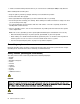
Chapter 9. Locations This chapter presents the locations of the ThinkPad X121e hardware components. Front view 1 11 9 2 3 8 10 4 7 5 6 1 Integrated camera 7 Touch pad 2 Power switch 8 TrackPoint buttons 3 Security keyhole 9 TrackPoint pointing stick 4 ac power connector 10 UltraNav pointing device 5 USB connector 11 Built-in digital microphone 6 Always on USB connector For the description of the power status indicator, see Chapter 5 “Status indicators” on page 41.
Rear view 1 2 3 4 5 6 7 1 Sleep (standby) status indicator 5 HDMI port 2 Combo audio jack 6 Fan louvers 3 Ethernet connector 7 External monitor connector 4 USB connector For the description of the power status indicator, see Chapter 5 “Status indicators” on page 41. Bottom view 2 1 2 3 1 Battery pack 3 Bottom slot cover 2 Battery pack latch For the description of the power status indicator, see Chapter 5 “Status indicators” on page 41.
Chapter 10. Parts list This chapter contains following lists of the service parts. • “Overall” on page 82 • “LCD FRUs” on page 90 • “Keyboard” on page 94 • “Miscellaneous parts” on page 95 • “ac power adapters” on page 95 • “Power cords” on page 96 • “Recovery discs” on page 97 • “Common service tools” on page 102 Notes: • Each FRU is available for all types or models, unless specific types or models are specified.
Overall 1 21 20 19 2 18 17 3 4 16 15 5 6 14 13 12 7 8 9 10 11 82 Hardware Maintenance Manual
Table 33. Parts list-Overall No. FRU (Overall) FRU no.
Table 33. Parts list-Overall (continued) No. FRU (Overall) FRU no. CRU ID 5 Battery pack, 6 cell Li-ion (2.8 Ah) • 3045-CTO, 62x, 63x, 64x, 65x, 66x, 67x, 68x, 6Ax, 6Bx, 6Cx, 6Dx, 6Fx, 6Jx, 6Mx, 6Qx, 6Rx, 6Sx, 6Tx, 6Ux • 3048-CTO, 22x, 23x, 24x, 25x, 29x, 2Ax, 2Bx, 2Cx, 2Mx, 2Nx, 2Px, 2Qx, 2Vx • 3049-CTO • 3051-CTO, 53x, 54x, 55x, 56x, 57x, 5Bx, 5Dx, 5Ex, 5Nx, 5Px, 5Qx, 5Rx • 3053-CTO, 22x, 23x, 25x, 26x, 27x, 28x, 2Dx • 3055-CTO, 42T4959 * 5 Battery pack, 6 cell Li-ion (2.
Table 33. Parts list-Overall (continued) No. FRU (Overall) FRU no.
Table 33. Parts list-Overall (continued) No. FRU (Overall) FRU no.
Table 33. Parts list-Overall (continued) No. FRU (Overall) FRU no. CRU ID 13 Bluetooth daughter card (BDC-3.0) • 3045-CTO, 63x, 64x, 65x, 66x, 67x, 68x, 6Dx, 6Fx, 6Jx, 6Kx, 6Mx, 6Px, 6Qx, 6Rx, 6Sx, 6Tx, 6Ux • 3048-CTO, 22x, 23x, 24x, 25x, 28x, 2Bx, 2Cx, 2Mx, 2Nx, 2Px, 2Qx, 2Vx • 3049-CTO • 3051-CTO, 53x, 54x, 55x, 56x, 57x, 58x, 59x, 5Nx, 5Px, 5Qx, 5Rx • 3053-CTO, 25x, 26x, 2Dx, • 3055-CTO 60Y3271 N 13 Bluetooth daughter card (BDC-3.
Table 33. Parts list-Overall (continued) No. FRU (Overall) FRU no.
Table 33. Parts list-Overall (continued) No. FRU (Overall) FRU no.
Table 33. Parts list-Overall (continued) No. FRU (Overall) FRU no. CRU ID 21 91P9642 * - TrackPoint caps ac power adapter (see “ac power adapters” on page 95) LCD FRUs In ThinkPad X121e models, the type of the LCD is 11.6-inch HD LED-backlight LCD (Table 34 “Parts list-LCD” on page 91).
1 2 3 4 5 6 7 Table 34. Parts list-LCD No. FRU (LCD) FRU no. CRU ID 1 LCD front bezel 04W2229 N 2 LCD module, 11.6-inch HD anti-glare 04W1594 N Chapter 10.
Table 34. Parts list-LCD (continued) No. FRU (LCD) FRU no.
Table 34. Parts list-LCD (continued) No. FRU (LCD) FRU no.
Table 34. Parts list-LCD (continued) No. FRU (LCD) FRU no. CRU ID 7 LCD cover kit, red, without Wireless WAN • 3045-CTO • 3048-CTO • 3049-CTO • 3051-CTO • 3053-CTO • 3055-CTO 04W2250 N 7 LCD cover kit, black, without Wireless WAN • 3045-CTO • 3048-CTO • 3049-CTO • 3051-CTO • 3053-CTO • 3055-CTO 04W2251 N Keyboard Table 35. Parts list-Keyboard Language FRU no.
Table 35. Parts list-Keyboard (continued) Language FRU no. Polish 63Y0068 63Y0140 Portuguese 63Y0069 63Y0141 Russian 63Y0070 63Y0142 Slovak 63Y0071 63Y0143 Slovenian 63Y0072 63Y0144 Spanish 63Y0050 63Y0129 Swiss 63Y0074 63Y0146 Thai 63Y0081 63Y0153 Traditional Chinese 63Y0080 63Y0152 Turkish 63Y0075 63Y0147 Turkish-F 63Y0082 63Y0154 U.K. English 63Y0076 63Y0148 U.S. English 63Y0047 63Y0119 U.S.
Power cords A ThinkPad power cord for a specific country or region is usually available only in that country or region: Table 39. Parts list–2-pin power cords Country or region FRU no. Argentina • Models: CTO, xxY 42T5020 42T5105 * Brazil • Models: CTO, xxP 42T5180 42T5183 Canada, U.S. • Models: CTO, xxF, xxL, xxS, xxU 42T5008 42T5093 Japan • Models: CTO, xxE, xxJ 42T5014 42T5099 CRU ID Table 40. Parts list–3-pin power cords Country or region FRU no.
Recovery discs Windows XP Professional (32-bit) DVDs Windows XP Professional is preinstalled as the operating system in the following models: • 3045-CTO • 3048-CTO • 3049-CTO • 3051-CTO • 3053-CTO • 3055-CTO Table 41.
• 3053-CTO • 3055-CTO Table 42. Parts list-Windows Vista Business (32-bit) recovery DVDs Language P/N CRU ID US English 04T1844 N Windows 7 Home Basic (32-bit) DVDs Windows 7 Home Basic (32-bit) is preinstalled as the operating system in the following models: • 3045-CTO, 6Fx, 6Gx, 6Hx, 6Jx, 6Kx, 6Mx, 6Px • 3048-CTO, 29x, 2Ax, 2Bx, 2Cx, 2Dx, 2Kx, 2Lx • 3049-CTO • 3051-CTO, 55x, 57x, 59x • 3053-CTO, 26x, 28x, 2Ax, 2Bx • 3055-CTO Table 43.
Windows 7 Home Premium (64-bit) DVDs Windows 7 Home Premium (64-bit) is preinstalled as the operating system in the following models: • 3045-CTO, 6Sx • 3048-CTO, 24x, 25x, 2Mx • 3049-CTO • 3051-CTO, 5Rx • 3053-CTO, 22x, 23x • 3055-CTO Table 45.
• 3051-CTO, 52x, 5Ax, 5Bx, 5Dx, 5Ex • 3053-CTO • 3055-CTO Table 46.
Table 47. Parts list-Windows 7 Professional (64-bit) recovery DVDs (continued) Language P/N Slovak 03W8001 Spanish 03W8002 Traditional Chinese 03W7987 Turkish 03W8004 US English 03W8006 US English disable 03W8005 CRU ID Windows 7 Ultimate (32-bit) DVDs Windows 7 Ultimate (32-bit) is preinstalled as the operating system in the following models: • 3045-CTO • 3048-CTO • 3049-CTO • 3051-CTO • 3053-CTO • 3055-CTO Table 48.
Table 50. Parts list-Windows 7 Starter (32-bit) recovery DVDs Language P/N CRU ID Arabic 04T1919 N Brazilian Portuguese 04T1920 French 04T1922 Portuguese 04T1923 Russian 04T1924 Spanish 04T1925 Turkish 04T1926 Indian English 04T1921 US English 04T1927 Common service tools Table 51. Parts list-Common service tools Tool P/N Screwdriver kit 95F3598 1/4" drive spinner handle 1650840 1/4" Sq.
Appendix A. Notices Lenovo may not offer the products, services, or features discussed in this document in all countries. Consult your local Lenovo representative for information on the products and services currently available in your area. Any reference to a Lenovo product, program, or service is not intended to state or imply that only that Lenovo product, program, or service may be used.
Electronic emissions notices For electronic emission information on Class B digital devices, refer to the corresponding information in the User Guide. Trademarks The following terms are trademarks of Lenovo in the United States, other countries or both: Active Protection System Lenovo ThinkPad ThinkVantage TrackPoint Windows is a trademark of the Microsoft group of companies.
Part Number: 0A96013 Printed in China (1P) P/N: 0A96013 *0A96013*