Hardware Maintenance Manual xSeries 220 IBM
Hardware Maintenance Manual xSeries 220 IBM
Note: Before using this information and the product it supports, be sure to read the general information under “Notices” on page 168.
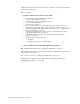
About this manual This manual contains diagnostic information, a Symptom-to-FRU index, service information, error codes, error messages, and configuration information for the xSeries 220. Important: This manual is intended for trained servicers who are familiar with IBM PC Server products. Important safety information Be sure to read all caution and danger statements in this book before performing any of the instructions. Leia todas as instruções de cuidado e perigo antes de executar qualquer operação.
Lea atentamente todas las declaraciones de precaución y peligro ante de llevar a cabo cualquier operación. Online support Use the World Wide Web (WWW) to download Diagnostic, BIOS Flash, and Device Driver files. File download address is: http://www.us.pc.ibm.com/files.html IBM online addresses The HMM manuals online address is: http://www.us.pc.ibm.com/cdt/hmm.html The IBM PC Company Support Page is: http://www.us.pc.ibm.com/support/index.html The IBM PC Company Home Page is: http://www.pc.ibm.
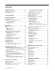
Contents About this manual . . . . . . . . . . . . . . . . . . . iii Important safety information . . . . . . . . . . . . . . . . . . . . . . iii Online support. . . . . . . . . . . . . . . . . . . . . . . . . . . . . . . . . . . iv IBM online addresses . . . . . . . . . . . . . . . . . . . . . . . . . . iv General checkout. . . . . . . . . . . . . . . . . . . . . 1 General information. . . . . . . . . . . . . . . . . . . 3 Features and specifications . . . . . . . . . . . . . . . . . . . . . . . .
Undetermined problems . . . . . . . . . . . . . . . . . . . . . . . . 124 Parts listing . . . . . . . . . . . . . . . . . . . . . . . 127 System . . . . . . . . . . . . . . . . . . . . . . . . . . . . . . . . . . . . . . . . 128 Keyboards. . . . . . . . . . . . . . . . . . . . . . . . . . . . . . . . . . . . . 130 Power cords . . . . . . . . . . . . . . . . . . . . . . . . . . . . . . . . . . . 131 Related service information . . . . . . . . . . 133 Safety information. . . . . . . . . . . . . . . . . . .
General checkout The server diagnostic programs are stored in upgradable read-only memory (ROM) on the system board. These programs are the primary method of testing the major components of the server: The system board, Ethernet controller, video controller, RAM, keyboard, mouse (pointing device), diskette drive, serial ports, hard drives, and parallel port. You can also use them to test some external devices. See “Diagnostic programs and error messages” on page 13.
YES. Schedule maintenance with the customer. Shut down all systems related to the cluster. Run storage test. NO. Go to step 2. 2. IF THE SYSTEM IS NOT PART OF A CLUSTER: • • • • • • • • • • 3. Power-off the computer and all external devices. Check all cables and power cords. Set all display controls to the middle position. Power-on all external devices. Power-on the computer. Record any POST error messages displayed on the screen.
General information Features and specifications . . . . . . . . . . . . . . . . . . . . 4 Server features . . . . . . . . . . . . . . . . . . . . . . . . . . . . . . . 5 Reliability, availability, and serviceability . . . . . . . . 6 Server controls and indicators . . . . . . . . . . . . . . . . . 6 Starting the server . . . . . . . . . . . . . . . . . . . . . . . . . . . 8 Turning off the server . . . . . . . . . . . . . . . . . . . . . . . .
Features and specifications This section provides a summary of the features and specifications of the xSeries 220 server. Microprocessor: • • • • Intel® Pentium® III microprocessor with MMX™ technology and SIMD extensions 256 KB* ECC, level-2 cache (min.) 133 MHz front-side bus (FSB) Support for up to two microprocessors Memory: • • • • Standard: 128 MB1* Maximum: 4 GB* Type: 133 MHz, ECC, SDRAM, registered DIMMs Slots: 4 dual in-line Drives standard: • • • Diskette: 1.
• • • • Keyboard port Mouse port IDE controller port Video port Acoustical noise emissions: • Sound power, idling: 5.9 bel maximum • Sound power, operating: 6.1 bel maximum Environment: • Air temperature: • — Server on: 10º to 35º C (50.0º to 95.0º F). Altitude: 0 to 914 m (2998.7 ft) — Server on: 10º to 32º C (50.0º to 89.6º F). Altitude: 914 m (2998.7 ft) to 2133 m (6998.0 ft) — Server off: 10º to 43º C (50.0º to 109.4º F). Maximum altitude: 2133 m (6998.
• System-management capabilities System-management software is included with the server to manage the functions of the server locally and remotely. Refer to the documentation that comes with the system-management software for more information. • Integrated network environment support The server comes with an Ethernet controller on the system board. This Ethernet controller has an interface for connecting to 10-Mbps or 100-Mbps networks.
CD-ROM eject button CD-ROM drive activity light Diskette-eject button Diskette drive activity light SCSI activity light Power-on light Power-control button System error light CD-ROM eject button: Press this button to release a CD from the drive. CD-ROM drive activity light: When this light is on, it indicates that the CD-ROM drive is in use. Diskette-eject button: Press this button to release a diskette from the drive.
Cover-release latch Key lock Starting the server After you plug the power cord of your server into the power supply and an electrical outlet, the server can start in any of the following ways: • You can press the power-control button on the front of the server to start the server. Notes: 1. You can install a circular disk over the power-control button to prevent accidental manual power-off. This disk, known as the power-control button shield, comes with your server. 2.
— The Wake on LAN feature is enabled in the Configuration/Setup Utility program. — A supported Wake on LAN adapter is installed in PCI slot 1 and is connected to the system board with the 3-pin auxiliary power connector. Notes: • 1. See “Choices available from the Configuration/Setup main menu” on page 30 for a description of the Configuration/Setup Utility program. 2. See “System board options connectors” on page 55 for connector locations. 3.
10 Hardware Maintenance Manual: xSeries 220
Diagnostics Diagnostic tools overview . . . . . . . . . . . . . . . . . . . . 11 POST . . . . . . . . . . . . . . . . . . . . . . . . . . . . . . . . . . . . . . 11 POST beep codes . . . . . . . . . . . . . . . . . . . . . . . . . . . . 12 POST error messages . . . . . . . . . . . . . . . . . . . . . . . . 12 POST error log . . . . . . . . . . . . . . . . . . . . . . . . . . . . . . 12 Small computer system interface messages . . . . . 12 Diagnostic programs and error messages . . . . . . .
If POST detects a problem, more than one beep sounds and an error message appears on the screen. See “POST beep codes” and “POST error messages” for more information. Notes: 1. If you have a power-on password set, you must type the password and press Enter, when prompted, before POST will continue. 2. A single problem might cause several error messages. When this occurs, work to correct the cause of the first error message.
SCSI Messages All Description One or more of the following might be causing the problem. • A failing SCSI device (adapter, drive, controller) • An improper SCSI configuration • Duplicate SCSI IDs in the same SCSI chain • An improperly installed SCSI terminator • A defective SCSI terminator • An improperly installed cable • A defective cable Action: Verify that: • The external SCSI devices are turned on. External SCSI devices must be turned on before the server.
iii is the three-digit device ID. date is the date that the diagnostic test was run and the error recorded. cc is the check digit that is used to verify the validity of the information. text message is the diagnostic message that indicates the reason for the problem. Text messages The diagnostic text message format is as follows: Function Name: Result (test specific string) where: Function Name is the name of the function being tested when the error occurred.
Notes: a. If the server stops during testing and you cannot continue, restart the server and try running the diagnostic programs again. b. The keyboard and mouse (pointing device) tests assume that a keyboard and mouse are attached to the server. c. If you run the diagnostic programs with no mouse attached to the server, you will not be able to navigate between test categories using the Next Cat and Prev Cat buttons.
Power checkout Power problems can be difficult to troubleshoot. For instance, a short circuit can exist anywhere on any of the power distribution busses. Usually a short circuit will cause the power subsystem to shut down because of an overcurrent condition. A general procedure for troubleshooting power problems is as follows: 1. Power off the system and disconnect the AC cord(s). 2. Check for loose cables in the power subsystem.
Switch block Flash ROM page-swap jumper (J38) 3. Move J38 to the lo setting (pins 1 and 2) to enable BIOS recovery mode. 4. Reconnect all external cables and power cords and turn on the peripheral devices. 5. Insert the BIOS flash diskette in the diskette drive. 6. Restart the server. The system begins the power-on self-test (POST). 7. Select 1 - Update POST/BIOS from the menu that contains various flash (update) options. 8.
Front panel and system board LEDs The server does not contain a diagnostic or information panel. The system error LED is on the front panel inside the server. All of the remaining error LEDs are on the system board, adjacent to the failing components. See “Diagnostic LEDs” for information on identifying problems using these LEDs.
System Error LED (on the front panel) System board LED Cause On System error (front panel) The diagnostic LEDs have detected a system error. Off None The diagnostic LEDs have not detected a system error. Table 2. Diagnostic LEDs. Replacing the battery When replacing the battery you must replace it with a lithium battery of the same type, from the same manufacturer. To avoid possible danger read and follow the safety statement below.
d. Ensure that the battery clip is touching the base of the battery socket by pressing gently on the clip. 5. Insert the new battery: a. Tilt the battery so that you can insert it into the socket, under the battery clip. b. As you slide it under the battery clip, press the battery down into the socket. 6. Reinstall the server cover and connect the cables. 7. Turn on the server. 8. Start the Configuration/Setup Utility program and set configuration parameters. • Set the system date and time.
Diagnosing errors To find solutions to problems that have definite symptoms, see “Error symptoms” on page 117. If you cannot find the problem there, go to “Starting the diagnostic programs” on page 14 to test the server. If you have just added new software or a new option and the server is not working, do the following before using the error symptoms table: • Remove the software or device that you just added. • Run the diagnostic tests to determine if the server is running correctly.
Ethernet controller problem The server stops running when loading device drivers. Suggested Action The PCI BIOS interrupt settings are incorrect. Check the following: • Determine if the interrupt (IRQ) setting assigned to the Ethernet controller is also assigned to another device in the Configuration/Setup Utility program. Although interrupt sharing is allowed for PCI devices, some devices do not function well when they share an interrupt with a dissimilar PCI device.
Ethernet controller problem The Ethernet controller stopped working without apparent cause. Suggested Action Check the following: • Run diagnostics for the Ethernet controller. • Try a different connector on the hub. • Reinstall the device drivers. Refer to your operating-system documentation and to the ServerGuide information. If the problem remains, call for service. Table 3. Ethernet troubleshooting chart.
Message Description Duplicate slot numbers detected. Explanation: An attempt has been made to bind the same slot number more than once. Action: Check the slot numbers entered during the bind. Adapter slot numbers must be valid and unique. If the problem persists, contact your network supplier. ’Xxx’ is not supported for AFT team. Explanation: A bind command has been issued for adapters not supported by AFT.NLM. Action: Make sure that you attempt to bind only adapters supported by AFT.NLM.
Message Description Failed to allocate resources tags. Explanation: An unknown error has occurred when trying to allocate needed resources for the AFT module. Action: Check Server Configuration. If the problem persists, contact your network supplier. Please unload all LAN drivers before unloading AFT.NLM. Explanation: An attempt was made to unload the AFT.NLM module before unloading the adapter driver. Action: Unload the adapter driver before unloading the AFT module. Table 4.
Error code (hex) 0x0F Description Explanation: Could not allocate enough memory for other structures. Action: 1. From the Windows NT desktop, select Start -> Control Panel -> Networks -> Adapters. 2. Select your IBM Ethernet adapter from the list. 3. Select Properties -> Advanced. 4. Lower the value for the resource named in the message. 0x10 Explanation: Did not find any Ethernet controllers. Action: Using the Configuration/Setup Utility, make sure that Ethernet is enabled.
Event ID Type Description 04 Error Explanation: Unable to bind to physical adapter. Action: Reconfigure the adapter team by double-clicking the PROSet icon in the control panel. 05 Error Explanation: Unable to initialize an adapter team. Action: Reconfigure the adapter team by double-clicking the PROSet icon in the control panel. 06 Informational Explanation: Team nn. Primary adapter is initialized. Action: None. 07 Informational Explanation: Team nn. Secondary adapter is initialized.
Event ID 21 Type Warning Description Explanation: Team nn. Primary adapter does not sense any Probes. Possible reason: partitioned Team. Action: Make sure the cables of the adapter team are connected to the same LAN segment. Reconfigure the team if necessary. Table 6. NDIS (Windows NT or Windows 2000) driver teaming messages for the Ethernet controller.
Configuring the server Using the Configuration/Setup Utility program . 29 Starting the Configuration/Setup Utility program . 30 Choices available from the Configuration/Setup main menu . . . . . . . . . . . . . . . . . . . . . . . . . . . . . . . . . 30 Using passwords . . . . . . . . . . . . . . . . . . . . . . . . . . . . 33 Using the SCSISelect utility program . . . . . . . . . . . 35 Starting the SCSISelect utility program. . . . . . . . . 35 Choices available from the SCSISelect menu . . . .
Starting the Configuration/Setup Utility program To start the Configuration/Setup Utility program, do the following: 1. Turn on the server and watch the monitor screen. 2. When the message Press F1 for Configuration/Setup appears, press F1. Notes: 3. a. You can set an administrator password through the Configuration/Setup Utility program only if the optional system management adapter is installed in your server. b.
Changes that you make to configuration settings appear on this summary screen. You cannot edit the fields. This choice appears on both the full and limited Configuration/Setup Utility menus. • System Information Select this choice to display information about the server. Changes that you make on other menus might appear on this summary screen. You cannot edit any fields. The System Information choice appears only on the full Configuration/Setup Utility main menu.
checks for a startable diskette in the diskette drive, then checks the hard disk drive in bay 1, and then checks a network adapter. If you have the appropriate Ethernet adapter and Wake on LAN software installed and enabled in the server, the server uses the alternative startup sequence instead of the primary startup sequence. The default for Wake on LAN is Disabled. If the Boot Fail Count choice is enabled, you can restore the BIOS system defaults after three consecutive boot failures.
Select this choice to assign IRQs and program the master latency timer. — PCI Slot/Device Information Note: This choice is available on the Configuration/Setup Utility menu only if the optional system management adapter is installed in your server. Select this choice to view and identify system resources that are used by PCI devices. PCI devices automatically communicate with the server configuration information. This usually results in automatic configuration of a PCI device.
• If an administrator password has been set, enter the administrator password at the power-on prompt. (If necessary, see “Administrator password” for details.) Start the Configuration/Setup Utility program and change the power-on password. • Start the Configuration/Setup Utility program, and change the power-on password. • Change the position of the password-override switch as described in “Setting the password-override switch”. • Remove the battery and then reinstall the battery.
Select this choice to set an administrator password. The administrator password provides access to all choices on the Configuration/Setup Utility main menu. You can set, change, or delete both the administrator and power-on passwords, and allow a power-on password to be changed by the user. Attention: If an administrator password is set and then forgotten, it cannot be overridden or removed. You must replace the system board. The following table provides a summary of the password features.
4. 5. 36 Use the arrow keys to select a choice from the menu: • Press Esc to return to the previous menu. • Press the F5 key to switch between color and monochrome modes (if your monitor permits). Follow the instructions on the screen to change the settings of the selected items; then, press Enter.
Choices available from the SCSISelect menu The following choices appear on the SCSISelect Utility menu: • Configure/View Host Adapter Settings Select this choice to view or change the SCSI controller settings. To reset the SCSI controller to its default values, press F6; then, follow the on-screen instructions. You can view or change the following controller settings: — Host Adapter SCSI ID Select this choice to view the SCSI controller ID, which is usually 7.
Using the Preeboot eXecution Environment boot agent utility program The Preeboot eXecution Environment (PXE) Boot Agent is a built-in, menu-driven configuration utility program that you can use to: • Change network startup (boot) protocols • Change network startup (boot) order • Set menu wait times • Select operating system wake up support Starting the PXE boot agent utility program The following sections provide the instructions needed to start the PXE Boot Agent Utility and descriptions of the ava
• Setup time wait menu Select this choice to set the amount of time (in seconds) that the system will pause during initialization for a Ctrl+S input. — 2 seconds (default) — 3 seconds — 5 seconds — 8 seconds • Legacy OS wake up support Select this choice to allow/disallow a non-windows operating system to use adapter remote wake up capability.
40 Hardware Maintenance Manual: xSeries 220
Tower-to-rack conversion Use the following steps to prepare the system for rack installation: Important: Read “Safety information” on page 133 before continuing with this procedure. 1. Shut down the operating system and remove all media from the drives, such as diskettes, CDs, optical disks, or tapes. 2. Turn off the system and any attached devices. 3. Disconnect all power cords from the system and electrical outlets. 4.
Cover-release latch Key lock Figure 1. Removing the left-side cover 6. Remove the support bracket assembly. a. If there is a fan attached to the support bracket assembly, note where the fan cable is connected to the system board; then, disconnect the fan cable from the system board. Note: Refer to the system service label for system board connector locations. b. 42 Grasp the rear of the support bracket assembly and rotate it away from the system.
Support bracket assembly Figure 2. Removing the support bracket assembly c. Pull the front of the support bracket assembly away from the system and set the assembly aside for later installation.
7. Remove the front door and bezel assembly. a. Grasp the end of the blue bezel-release lever inside of the system; then, move the lever forward to release the front door and bezel assembly. Figure 3. Removing the front door and bezel assembly b. 8. Carefully turn the system open-side up on a flat surface; then, remove the four feet from the system. a.
Figure 4. Rotating the front feet b. Carefully use a flat-blade screwdriver to push in the tabs on each of the four feet and remove them from the system. Store the feet for possible future use. Figure 5. Removing the system feet 9. Move the power-switch and LED panel to the rack-orientation location. a. If the system has hot-swap drives installed, note their locations; then, remove them (see “Installing a hot-swap hard disk drive in bay 5, 6, or 7” on page 72) and place them in a safe place. b.
c. To remove the power-switch and LED panel, press in on the tab on the left side of the panel; then, squeeze the top and bottom of the right-side of the panel and carefully pull the panel away from the system. Drive cage Rack-orientation for switch Tower-orientation for switch Figure 6. Relocating the power-switch and LED panel d. Note where the power-switch and LED panel cable connects to the system board; then, carefully disconnect the cable from the system board.
Figure 7. Installing the top cover 11. Turn the system back to the tower-orientation; then, remove the top handle. a. Carefully use a flat-blade screwdriver to push in the tabs inside the plastic cover on the top of the system; then, remove the plastic cover and store it for possible future use. Figure 8. Removing the plastic cover from the handle b. Grasp the metal handle and slide it backwards until you can lift it away from the system. Store the metal handle for possible future use. Figure 9.
12. Remove the right-side cover. a. From the rear of the system, remove the four screws that hold the right-side cover in place. Save all four screws for installing the new bottom cover. Right-side cover Figure 10. Removing the right-side cover b. Slide the right-side cover toward the rear of the system to remove it. Store the cover for possible future use. 13. Install the new bottom cover that comes with the conversion kit. a.
c. Use three of the screws that you removed earlier to secure the bottom cover; then, use the fourth screw to secure the power supply. 14. If your system has hot-swap drives installed, remove the hot-swap drive bay filler panel from the new bezel that comes with the conversion kit. Note: Attach the SCSI ID label that comes with the conversion kit on the front of the bezel, just above where you removed the hot-swap drive bay filler panel. Hot-swap drive bay filler panel Bezel Figure 12.
16. To install the new system bezel that comes with the conversion kit, align the tab on the back of the bezel with the tab opening on the left-front of the system; then, swing the bezel toward the system and press until it snaps into place. Figure 14. Installing the new system bezel 17. Install the release-latch-bracket assemblies on the system. a. Align the bracket marked with an L with the holes on the left side of the system; then, use two M3.5 screws to attach the bracket to the system.
18. Attach the four rack-support wheels to the sides of the system. Rack-support wheels Rack-support wheels Figure 16.
52 Hardware Maintenance Manual: xSeries 220
Installing options Major components of the xSeries 220 server . . . . . 54 System board . . . . . . . . . . . . . . . . . . . . . . . . . . . . . . . 55 System board options connectors . . . . . . . . . . . . . . 55 System board internal cable connectors. . . . . . . . . 55 System board external port connectors . . . . . . . . . 57 System board jumpers and switches . . . . . . . . . . . 57 Before you begin . . . . . . . . . . . . . . . . . . . . . . . . . . . . 58 System reliability considerations . . . . .
Major components of the xSeries 220 server Note: The illustrations in this document might differ slightly from your hardware. The following illustration shows the locations of major components in the server.
System board The illustrations in the following sections show the components on the system board. System board options connectors The following illustration identifies system-board connectors for user-installable options.
Microprocessor fan 2 (J2) Microprocessor fan 1 (J3) Fan 2 power (J18) Main power (J1) Diskette drive (J27) 2 DASD I C (J43) Fan 1 power (J10) IDE (J30) Fan 3 power (J22) (not used) Wake on LAN (J20) SCSI channel (J41) Notes: 56 1. If the server and operating system support system-management functions and if the optional system management adapter is installed in the server, the system management connector (J32) is dedicated for use by the system management adapter. 2.
System board external port connectors The following illustration identifies system-board connectors for external devices. Keyboard/Mouse USB Serial A Parallel Serial B Ethernet Video Note: For information on adding external SCSI devices to the server, see “SCSI cabling requirements” on page 91. System board jumpers and switches The following illustration identifies the jumpers and switches on the system board.
The switch block contains microswitches 1 through 8. As pictured in this illustration, switch 8 is at the right of the switch block and switch 1 is at the left. The following table describes the function for each switch. The default setting is Off for all switches in the switch block. Switch number 8 Switch description Power-on password-override switch. When toggled to the side that is opposite the default position, bypasses the power-on password, if one is set. 7 Reserved. 6 Reserved.
Rotating the stabilizing feet The feet attached to the bottom cover rotate 90 degrees to provide additional stability for the server. Place the server in an upright position; then, rotate the feet a quarter turn away from the server. Carefully position the server on its feet. When you need to access the inside of the server to install options, you might find it easier to place the server on its side, so that the system board is facing you.
Cover-release latch Key lock Do the following to remove the left-side cover of the server: 1. Review the information in “Before you begin” on page 58. 2. Turn off the server and all attached devices and disconnect all external cables and power cords. 3. If necessary, unlock the server cover. 4. Pull out on the cover-release latch near the rear of the server cover; then, slide the cover toward the rear of the server and remove it.
Do the following to remove the bezel: 1. Review the information in “Before you begin” on page 58. 2. Turn off the server and peripheral devices and disconnect all external cables and power cords. 3. Remove the side cover (see “Removing the side cover” on page 59). 4. Press the bezel-release latch at the top of the server to disconnect the top of the bezel from the server. 5. Release the two tabs at the top edge of the bezel and pull the top of the bezel slightly away from the server. 6.
Do the following to remove the support bracket assembly: 1. Review the information in “Before you begin” on page 58. 2. Turn off the server and peripheral devices and disconnect all external cables and power cords. 3. Remove the side cover (see “Removing the side cover” on page 59). 4. If the server is a non-hot-swap model, continue with step 7.. 5.
Working with adapters You can install up to five peripheral component interconnect (PCI) adapters in the PCI slots on the system board of the server. See the xSeries 220 ServerProven list at http://www.ibm.com/pc/compat/ for a list of PCI adapters that the server supports. The server comes with an integrated video controller, which is a component on the system board. When you install a video adapter, the server BIOS automatically disables the integrated video controller.
The following illustration shows the location of the 33 MHz PCI slots on the system board. PCI slot 1 32-bit 33 MHz (J29) PCI slot 2 32-bit 33 MHz (J31) PCI slot 3 64-bit 33 MHz (J35) PCI slot 4 64-bit 33 MHz (J39) PCI slot 5 64-bit 33 MHz (J40) Adapter considerations Before you install adapters, review the following: • Locate the documentation that comes with the adapter and follow those instructions in addition to the instructions given in this chapter.
2 supports the optional system management adapter. For additional information on the optional system management adapter, refer to the documentation that comes with the adapter. Installing an adapter Expansion-slot cover Rear adapter retaining bracket Adapter Front adapter support bracket Attention: When you handle electrostatic discharge (ESD) sensitive devices, take precautions to avoid damage from static electricity.
Attention: Expansion-slot covers must be installed on all vacant slots. This maintains the electronic emission characteristics of the system and ensures proper cooling of system components. 7. Refer to the documentation that comes with your adapter for any cabling instructions. It might be easier for you to route cables before you install the adapter. 8. Remove the adapter from the static-protective package. Attention: Avoid touching the components and gold-edge connectors on the adapter. 9.
The following illustration shows how to reroute the SCSI cable. If you install a ServeRAID adapter and intend to use it with hot-swap, hard disk internal drives, remove the cable from the internal SCSI connector (J41) on the system board and connect it to the ServeRAID adapter. Note: You can also install a ServeRAID adapter in non-hot-swap models; however, non-hot-swap models do not support hot-swap hard disk drives. SCSI cable ServeRAID adapter SCSI connector (J41) 13.
Note: The illustrations in this document might differ slightly from your hardware. Bay 1 Bay 2 Bay 3 Bay4 Bay 5 Bay 6 Bay 7 To remove or install a drive, you must turn off the server first, unless you are removing or installing a hot-swap hard disk drive. Diskette drives, tape drives, and CD-ROM drives are removable-media drives. You can install removable-media drives in bays 1, 2, 3, and 4. You can install SCSI hard disk drives in bays 4, 5, 6, and 7. • The server comes with a 3.5-inch, 1.
Note: The electromagnetic interference (EMI) integrity and cooling of the server are both protected by having bays 1 through 4 covered or occupied. When you install a drive, save the filler panel from the bay, in case you later remove the drive and do not replace it with another. Preinstallation steps (all bays) Before you install drives in the server, verify that you have all the cables and any other equipment specified in the documentation that comes with the drive.
4. Insert a screwdriver into the slots on the front of the EMC shield, and remove the EMC shield from the bay. 5. If the drive is a laser product, observe the following safety precaution. CAUTION: When laser products (such as CD-ROMs, DVD drives, fiber optic devices, or transmitters) are installed, note the following: • Do not remove the covers. Removing the covers of the laser product could result in exposure to hazardous laser radiation. There are no serviceable parts inside the device.
Installing a non-hot-swap hard disk drive in bay 5, 6, or 7 To install a non-hot-swap hard disk drive in bay 5, 6, or 7, do the following: 1. Read the information in “Preinstallation steps (all bays)” on page 69. 2. Turn off the server and peripheral devices, and disconnect all external cables and power cords; then, remove the cover (see “Removing the side cover” on page 59 for details). 3. Remove the support bracket assembly (see “Removing the support bracket assembly” on page 61). 4.
6. Install rails on each drive in the drive cage: a. Pull the blue slide rails out of the plastic bag. b. Install the screws on the sides of the drive. c. Align the rails on the drive with the guide rails in the drive bay. d. Push the drive into the bay until it clicks into place. 7. Reinstall the drive cage in the server. Rotate the drive cage downward until it snaps into place. 8. Connect the server SCSI and power cables to the rear of the drives.
Hard disk drive activity light (green) Hard disk drive status light (amber) SCSI hot-swap hard disk drive connector Note: The hard disk drive activity light and hard disk drive status light on the backplane match the hard disk drive activity light and hard disk drive status light on the hot-swap drive. The following illustration shows the rear connectors on the hot-swap-drive backplane, as viewed from the rear of the server.
The following illustration shows how to install a hot-swap hard disk drive in the server. When you install hot-swap hard disk drives, install them in the following order: bay 7, bay 6, and bay 5. Filler panel Drive tray assembly Drive tray handle (in open position) Attention: • When you handle electrostatic discharge (ESD) sensitive devices, take precautions to avoid damage from static electricity.
5. If you have other options to install or remove, do so now.
Installing memory modules Adding memory to the server is an easy way to make programs run faster. You can increase the amount of memory in the server by installing options called memorymodule kits. Each kit contains one industry-standard, dual in-line memory module (DIMM). The server uses a noninterleaved memory configuration. The server comes with a dual in-line memory module (DIMM) that is installed on the system board in DIMM slot 1 (connector J19). Notes: 1.
1. Review the safety precautions in Statement 1 and Statement 5 in “Safety information” on page 133. 2. Review the information in “Before you begin” on page 58 and the documentation that comes with the option. 3. Turn off the server and peripheral devices, and disconnect all external cables and power cords; then, remove the cover (see “Removing the side cover” on page 59 for details). 4. Select the connector in which to install the DIMM. 5.
2. Obtain an SMP-capable operating system (optional). For a list of supported operating systems, see http://www.ibm.com/pc/compat/ on the World Wide Web. 3. The server comes with one microprocessor, which is installed in microprocessor connector U12 (the microprocessor connector that is closer to the power supply). This is the startup (boot) microprocessor.
5. Install the microprocessor: a. Touch the static-protective package containing the new microprocessor to any unpainted metal surface on the server; then, remove the microprocessor from the package. b. Orient the microprocessor over the microprocessor connector, as shown in the following illustration. Carefully press the microprocessor into the connector.
8. If you are installing a microprocessor that has a speed lower than 933 MHz, install the heat sink onto the microprocessor: VRM 2 (J12) Terminator card Microprocessor 1 Microprocessor 2 VRM 1 (J42) Heat sink Heat-sink retainer a. Peel the plastic protective strip off the bottom of the heat sink. Make sure that the square of thermal material is still on the bottom of the heat sink. b. Align and place the heat sink on top of the microprocessor. c.
9. If you are installing a microprocessor that has a speed of 933 MHz, install a fan sink onto the microprocessor and connect the fan-sink power cable to the system board: VRM 2 (J12) Terminator card Microprocessor fan 1 (J2) Microprocessor fan 2 (J3 ) Microprocessor VRM 1 (J42) Fan sink Fan-sink retainer a. Peel the plastic protective strip off the bottom of the fan sink. Make sure that the square of thermal material is still on the bottom of the fan sink. b.
11. Install the VRM that is included in the microprocessor kit. Attention: Use of other VRMs might cause the server to overheat. a. Center the VRM over the appropriate VRM connector: 1) If you installed the microprocessor in connector U11, press down on the latches on either side of connector J12, and install the VRM in connector J12. 2) If you installed the microprocessor in connector U12, press down on the latches on either side of connector J42, and install the VRM in connector J42.
a. Insert a small, flat-blade screwdriver into the tab on the fan-sink retainer (clip). b. Press down and in with the screwdriver handle to remove the fan-sink retainer from the fan sink. c. Firmly grasp the fan sink and lift it off the microprocessor. Store the fan sink in a safe, clean place with the bottom side up. The thermal material on the fan sink must stay clean if you intend to reuse the fan sink in the future. d.
Note: If you removed the support bracket assembly after you removed the cover, reinstall it before you install the cover. To install the server left-side cover: 1. Clear any cables that might impede the replacement of the cover. 2. Align the bottom tabs of the side cover with the matching slots in the server chassis; then, insert the tabs into the slots. 3. Close the cover-release latch to pull the cover forward and lock the cover in place. 4.
1. Read “Before you begin” on page 58 and the documentation that comes with your options. 2. Be sure the server and all attached devices are turned off. 3. Follow the instructions that come with the option to prepare it for installation and to connect it to the server. Note: If you are attaching a SCSI device, see “SCSI port” on page 91 for SCSI ID and cabling information.
2. The Devices and I/O Ports choice appears only on the full Configuration/Setup Utility menu. If you have set both levels of passwords (user and administrator), you must type the administrator password to access the full Configuration/Setup Utility menu. Parallel port The server has one parallel port.
Parallel port connector The following table shows the pin-number assignments for the 25-pin, female D-shell parallel-port connector on the system board.
Some application programs require specific ports, and some modems function properly only at certain serial port addresses. You might need to use the Configuration/Setup Utility program to change serial port address assignments to prevent or resolve address conflicts. Viewing or changing the serial-port assignments To view or change the serial-port assignments, do the following: 1. Restart the server and watch the monitor screen. 2. When the message Press F1 for Configuration/Setup appears, press F1. 3.
USB cables and hubs You need a 4-pin cable to connect devices to USB 1 or USB 2. If you plan to attach more than two USB devices, you must use a hub to connect the devices. The hub provides multiple connectors for attaching additional external USB devices. USB technology provides up to 12 megabits-per-second (Mbps) speed with a maximum of 127 external devices and a maximum signal distance of five meters (16 ft) per segment.
Auxiliary-device (pointing device) port The system board has one auxiliary-device port that supports a mouse or other pointing device. The following table shows the pin-number assignments for the auxiliary-device connector on the system board. 6 5 4 3 2 Pin 1 Signal 1 Data 2 Reserved 3 Ground 4 +5 V dc 5 Clock 6 Reserved Table 13. Auxiliary-device connector pin-number assignments . Video port The server comes with an integrated super video graphics array (SVGA) video controller.
Pin Signal Pin Signal Pin Signal 4 Not connected 9 PIN 14 Vertical synchronization (Vsync) 5 Digital return 10 Digital return 15 DDC SCL Table 14. Video-port connector pin-number assignments. SCSI port The server has an integrated small computer system interface (SCSI) controller with an internal connector (J41) on the system board. This controller supports an Ultra160 SCSI internal channel. This channel supports up to 15 SCSI devices.
SCSI connector pin-number assignments The following table shows the pin-number assignments for the 68-pin SCSI connectors.
Ethernet port The server comes with an integrated Ethernet controller. This controller provides an interface for connecting to 10-Mbps or 100-Mbps networks and provides full-duplex (FDX) capability, which enables simultaneous transmission and reception of data on the Ethernet local area network (LAN). To access the Ethernet port, connect a Category 3, 4, or 5 unshielded twisted-pair (UTP) cable to the RJ-45 connector on the rear of the server.
• Cisco Fast EtherChannel (FEC) creates a team of two to four adapters to increase transmission and reception thoughput. FEC also includes the AFT option. You can use FEC only with a switch that has FEC capability. Teaming requires you to install at least one additional Ethernet adapter. For additional information about the teaming modes, refer to the documentation that comes with these additional adapters.
Queue (HPQ) does not provide the precise priority levels of 802.1p tagging, it does assign traffic as either high or low priority and sends high-priority packets first. Therefore, if there are multiple applications on a system that is sending packets, the packets from the application with a filter are sent out first. HPQ does not change network routing, nor does it add any information to the packets. To assign HPQ, you can specify it using Priority Packet when you create or assign a filter.
Ethernet port connector The following table shows the pin-number assignments for the RJ-45 connector. These assignments apply to both 10BASE-T and 100BASE-TX devices. Pin Signal Pin Signal 1 +Transmit data 5 Not connected 2 -Transmit data 6 -Receive data 3 +Receive data 7 Not connected 4 Not connected 8 Not connected Table 16. Ethernet RJ-45 connector pin-number assignments.
FRU information (service only) Button kit . . . . . . . . . . . . . . . . . . . . . . . . . . . . . . . . . . 97 Hot-swap hard disk drive cage . . . . . . . . . . . . . . . . 98 Hot-swap backplane . . . . . . . . . . . . . . . . . . . . . . . . . 98 Power supply . . . . . . . . . . . . . . . . . . . . . . . . . . . . . . . 99 Rear fan . . . . . . . . . . . . . . . . . . . . . . . . . . . . . . . . . . . 100 System board . . . . . . . . . . . . . . . . . . . . . . . . . . . . . . 101 CD-ROM drive . . . . .
6. Disconnect the cable of the button kit from the system board. 7. Place a screwdriver against the bottom release latch of the button kit and gently press upward and slide the latch through the aperture. 8. Gently pinch together the upper release latches and slide the latches through the aperture and remove the button kit. Hot-swap hard disk drive cage Before you begin: • Read “Safety information” on page 133. • Review the information in “Before you begin” on page 58.
Note: The illustration above may differ slightly from your server. To remove the hot-swap backplane, do the following: 1. Power-off the server, if it is on. 2. Unplug the server. 3. Remove the front bezel (see “Removing the bezel” on page 60). 4. Remove the cover (see “Removing the side cover” on page 59). 5. Remove the support bracket (see “Removing the support bracket assembly” on page 61). 6. Remove any hard disk drives or drive fillers from the drives. 7.
To remove the power supply, do the following: 1. Power-off the server, if it is on. 2. Unplug the server. 3. Remove the cover (see “Removing the side cover” on page 59). 4. Disconnect internal cables from the planar and drives. 5. Remove the screws from the rear of the server. 6. Gently move the power supply away from the chassis and lift it out of the server. Rear fan Before you begin: 100 • Read “Safety information” on page 133. • Review the information in “Before you begin” on page 58.
Rear Fan Rubber extensions To remove the rear fan, do the following: 1. Power-off the server, if it is on. 2. Unplug the server. 3. Remove the cover (see “Removing the side cover” on page 59). 4. Remove the support bracket (see “Removing the support bracket assembly” on page 61). 5. Remove the fan cable from the system board. 6. Use side cutters to sever the four rubber extensions on the outside of the server. 7. Gently pry the fan away from the server and lift it up and out. 8.
To remove the system board, do the following: 1. Power-off the server, if it is on. 2. Unplug the server. 3. Remove the cover (see “Removing the side cover” on page 59). 4. Remove the front bezel (see “Removing the bezel” on page 60). 5. Remove the support bracket (see “Removing the support bracket assembly” on page 61). 6. Disconnect the cables. 7. Remove the adapter cards and both adapter retaining brackets (see “Installing an adapter” on page 65). 8.
To remove the CD-ROM drive, do the following: 1. Power-off the server, if it is on. 2. Unplug the server. 3. Remove the cover (see “Removing the side cover” on page 59). 4. Disconnect the cables. 5. Remove the screws from the CD-ROM drive cage. 6. Gently slide the floppy disk drive toward the rear of the server and lift it out. Floppy disk drive Before you begin: • Read “Safety information” on page 133. • Review the information in “Before you begin” on page 58.
6. Gently slide the floppy disk drive toward the rear of the server and lift it out. Bezel release latch Before you begin: • Read “Safety information” on page 133. • Review the information in “Before you begin” on page 58. To remove the bezel release latch, do the following: 1. Power-off the server, if it is on. 2. Unplug the server. 3. Remove the cover (see “Removing the side cover” on page 59). 4. Remove the front bezel (see “Removing the bezel” on page 60). 5.
To remove the top/side cover, do the following: 1. Power-off the server, if it is on. 2. Unplug the server. 3. Remove the cover (see “Removing the side cover” on page 59). 4. Remove the front bezel (see “Removing the bezel” on page 60). 5. Remove the handle assembly (see “Handle assembly”). 6. Remove the four screws from the back of the server and put them in a safe place. 7. Using a screwdriver, gently pry the cover away from the server in the rear and slide the unit away from the server.
To remove the handle cap, do the following: 1. Power-off the server, if it is on. 2. Unplug the server. 3. Use a flathead screwdriver to gently press in and down on the tabs located on the interior side wall of the handle. 4. Lift up on the handle cap to separate it from the handle support. To remove the handle support, do the following: 1. Power-off the server, if it is on. 2. Unplug the server. 3. Firmly grasp the handle support and slide it away from the front bezel. 4.
To remove the adapter retainer, do the following: 1. Power-off the server, if it is on. 2. Unplug the server. 3. Remove the side cover (see “Removing the side cover” on page 59). 4. Remove all adapter cards (see “Installing an adapter” on page 65). 5. Rotate the adapter retainer to the open position. 6. Grasp the adapter retainer and gently slide the top and bottom tabs out of the notches.
108 Hardware Maintenance Manual: xSeries 220
Symptom-to-FRU index Beep symptoms . . . . . . . . . . . . . . . . . . . . . . . . . . . . No beep symptoms . . . . . . . . . . . . . . . . . . . . . . . . . Diagnostic error codes . . . . . . . . . . . . . . . . . . . . . . Error symptoms. . . . . . . . . . . . . . . . . . . . . . . . . . . . 111 114 115 117 POST error codes . . . . . . . . . . . . . . . . . . . . . . . . . . .119 Processor board LEDs . . . . . . . . . . . . . . . . . . . . . . 124 ServeRAID . . . . . . . . . . . . . . . . . . . . . . .
Beep/Symptom FRU/Action 1-2-1 (Programmable Interval Timer failed) 1. System Board 1-2-2 (DMA initialization failed) 1. System Board 1-2-3 (DMA page register write/read failed) 1. System Board 1-2-4 (RAM refresh verification failed) 1. DIMM 2. System Board 1-3-1 (1st 64K RAM test failed) 1. DIMM 2. System Board 1-3-2 (1st 64K RAM parity test failed) 1. DIMM 2. Processor 3. System Board 1-4-3 (Interrupt vector loading test failed) 1.
Beep/Symptom FRU/Action 2-3-2 1. (Screen memory failed) System board 2-3-3 (Screen retrace failed) 1. System board 2-3-4 (Search for video ROM failed) 1. System board 2-4-1 (Video failed, screen believed operable) 1. System board 3-1-1 (Timer tick interrupt failed) 1. System Board 3-1-2 (Interval timer channel 2 failed) 1. System Board 3-1-3 (RAM test failed above address OFFFFH) 1. DIMM 2. Memory card 3. System board 3-1-4 (Time-of-Day clock failed) 1. Battery 2.
Beep/Symptom FRU/Action 1. Install or reseat the memory modules, then do a 3 boot reset. (See “Using the Configuration/Setup Utility program” on page 29.) 2. DIMMs 3. System Board 4-4-4 (I2C cable attached, system management adapter not functioning) 1. Verify correct cable installation. 2. Verify optional system management adapter is correctly installed in PCI slot 2. 3. System management adapter. Two Short Beeps (Information only, the configuration has changed) 1. Run Diagnostics 2.
Diagnostic error codes Note: In the following error codes, if XXX is 000, 195, or 197do not replace a FRU. The description for these error codes are: 000 The test passed. 195 The Esc key was pressed to abort the test. 197 This is a warning error and may not indicate a hardware failure. For all error codes, replace/follow the FRU/Action indicated. Error Code/Symptom FRU/Action 001-XXX-000 core tests) (Failed 1. System Board 001-XXX-001 tests) (Failed core 1.
Error Code/Symptom FRU/Action 1. Adapter 2. SCSI Backplane 3. Cable 035-XXX-SNN (Check System Error Log before replacing a FRU. S= number of failing PCI slot; NN = SCSI ID of failing fixed disk.) 1. Fixed Disk with SCSI ID NN on RAID adapter in PCI slot S. 035-253-S99 (RAID adapter initialization failure) 1. ServeRAID Adapter in slot S is not configured properly. Obtain the basic and extended configuration status and refer to the ServeRAID Hardware Maintenance Manual for more information. 2.
Error Code/Symptom 217-XXX-001 (Failed BIOS Fixed Disk test) Note: 1. Fixed Disk 2 1. Fixed Disk 3 1. Tape Cartridge, if user executed the Read/Write Tape Drive test (XXX = 256) 2. SCSI or power cable connected to the tape drive with SCSI ID NN 3. Tape drive with SCSI ID NN – refer to Help and Service Information appendix of tape drive’s User Guide. 4. I/O Legacy Board or SCSI Controller – run SCSI Controller diagnostic to determine of SCSI bus is functioning properly. 1.
General CD-ROM drive is not recognized. FRU/Action 1. Run Configuration/Setup, enable primary IDE channel. 2. Check cables and jumpers. 3. Check for correct device driver. 4. Run CD-ROM diagnostics. 5. CD-ROM drive 6. System Board Power switch does not work. 1. Verify that switch number 5 of switch block is Off. 2. Power Switch Assembly 3. System Board CD-ROM drive cable is not plugged in. 1. Make sure CD-ROM drive cable is plugged in.
Setup Action The Operating System Installation program continuously loops. Free up more space on the hard disk. ServerGuide won't start your NOS CD. Be sure the NOS CD you have is supported by ServerGuide. See the Setup and Installation CD label for a list of NOS versions supported. Can't install NOS - option is grayed out. Either there is no logical drive defined (ServeRAID systems) or the ServerGuide system partition is not present. Run the setup and configuration program.
Error Code/Symptom FRU/Action 1. Run Configuration/Setup 2. Battery 3. System Board 4. Microprocessor 101, 102, 106 (System and microprocessor error) 1. System Board 111 (Channel check error) 1. Failing adapter 2. DIMM 3. System board 114 (Adapter read-only memory error) 1. Failing adapter 2. Run diagnostics 129 (Internal cache error) 1. Microprocessor 2. Optional microprocessor (if installed) 151 (Real time clock error) 1. Run Diagnostics 2. Battery 3.
Error Code/Symptom FRU/Action 1. Run Configuration/Setup 2. System Board 186 (Security hardware control logic failed) 1. Run Configuration/Setup 2. System Board 187 (VPD serial number not set.) 1. Set serial number in Setup 2. System Board 188 (Bad EEPROM CRC #2) 1. Run Configuration/Setup 2. System Board 189 (Three attempts were made to access the server with invalid passwords) 1. Run Configuration/Setup, enter the administrator password 2. System Board.
Error Code/Symptom FRU/Action 1. Disconnect external cable on parallel port. 2. Run Configuration/Setup 3. System Board 1. Disconnect external cable on serial port. 2. Run Configuration/Setup 3. System Board 1. Disconnect external cable on serial port 2. Run Configuration/Setup 3. System board 1200 (microprocessor machine check) 1. Microprocessor 1800 (No more hardware interrupt available for PCI adapter) 1. Run Configuration/Setup 2. Failing Adapter 3. System Board 1.
Error Code/Symptom 00019701 (Microprocessor 1 failed BIST) FRU/Action 1. Microprocessor 1 2. System Board 00019702 (Microprocessor 2 failed BIST) 1. Microprocessor 2 2. System Board 00180100 (No room for PCI option ROM) 1. Run Configuration/Setup 2. Failing Adapter 3. System Board 1. Run Configuration/Setup 2. Failing Adapter 3. System Board 1. Run Configuration/Setup 2. Failing Adapter 3. System Board 1. Run Configuration/Setup 2. Failing Adapter 3.
Error Code/Symptom FRU/Action 1. Ensure all microprocessors are the same speed. 1. Hard Disk Drive 2. If RAID system, refer to the Hardware Maintenance Manual for the specific RAID adapter. 3. SCSI Backplane 4. Cable 5. System Board I9990305 (Fixed boot sector error, no operating system installed) 1. Install operating system to hard disk drive. I9990650 (AC power has been restored) 1. Check cable 2. Check for interruption of power supply 3.
3. Remove or disconnect the following (one at a time) until you find the failure (power-on the computer and reconfigure each time). • Any external devices • Surge suppressor device (on the computer) • Modem, printer, mouse, or non-IBM devices • Each adapter • Drives • Memory Modules (Minimum requirement = one 128 MB DIMM) Note: Minimum operating requirements are: 4. a. 1 Power Supply b. System Board c. 1 Microprocessor d. 1 Terminator Card in Slot 2 e.
126 Hardware Maintenance Manual: xSeries 220
Parts listing 12 14 © Copyright IBM Corp. 2000 21 24 25 23 26 22 27 29 28 1 19 20 18 17 2 16 15 4 5 3 6 13 7 8 9 10 11 This parts listing supports the following models: 21X, 22X, 2AX, 31X, 32X, 3AX, 41X, 42X, 4AX, 51X, 52X, 5AX.
System Index 128 System (xSeries 220) Models 21X, 22X, 2AX, 31X, 32X, 3AX, 41X, 42X, 4AX, 51X, 52X, 5AX FRU No. 1 Chassis (All models) 06P5853 2 Cover, side/top (All models) 19K4957 3 Handle kit (All models) 19K4934 4 Bar release (All models) 19K4946 5 Handle support (All models) 19K4936 6 Front bezel (All models) 00N7066 7 48X CD-ROM (Primary) (All models) 19K1531 7 48X CD-ROM (Alternate) (All models) 09N0737 7 48X CD-ROM (Alternate) (All models) 19K1535 8 EMC shield, 5.
System (xSeries 220) Models 21X, 22X, 2AX, 31X, 32X, 3AX, 41X, 42X, 4AX, 51X, 52X, 5AX Index FRU No. 27 Retainer (All models) 19K4945 28 80MM fan assembly (All models) 22P2462 29 Power supply, 330W API-CR (All models) 00N7718 Hard disk drive slim blank bezel (hot swap only) (Models 2AX, 3AX, 4AX, 5AX only) 00N7259 Shield, planar EMC kit (All models) 06P5851 Misc.
System (xSeries 220) Models 21X, 22X, 2AX, 31X, 32X, 3AX, 41X, 42X, 4AX, 51X, 52X, 5AX Index FRU No.
Power cords Power cord FRU No.
132 Hardware Maintenance Manual: xSeries 220
Related service information Note: The service procedures are designed to help you isolate problems. They are written with the assumption that you have model-specific training on all computers, or that are familiar with the computers, functions, terminology, and service information provided in this manual. Safety information The following section contains the safety information that you need to be familiar with before servicing an IBM computer.
• Reinstall all covers correctly before returning the machine to the customer. Electrical safety CAUTION: Electrical current from power, telephone, and communication cables can be hazardous. To avoid personal injury or equipment damage, disconnect the attached power cords, telecommunication systems, networks, and modems before you open the server covers, unless instructed otherwise in the installation and configuration procedures. Observe the following rules when working on electrical equipment.
Observe the special safety precautions when you work with very high voltages; these instructions are in the safety sections of maintenance information. Use extreme care when measuring high voltages. • Regularly inspect and maintain your electrical hand tools for safe operational condition. • Do not use worn or broken tools and testers. • Never assume that power has been disconnected from a circuit. First, check that it has been powered-off.
2. Power-off the computer. Disconnect the power cord. 3. Check the power cord for: a. A third-wire ground connector in good condition. Use a meter to measure third-wire ground continuity for 0.1 ohm or less between the external ground pin and frame ground. b. The power cord should be the appropriate type as specified in the parts listings. c. Insulation must not be frayed or worn. 4. Remove the cover. 5. Check for any obvious non-IBM alterations.
Grounding requirements Electrical grounding of the computer is required for operator safety and correct system function. Proper grounding of the electrical outlet can be verified by a certified electrician.
• Connect and disconnect cables as described in the following table when installing, moving, or opening covers on this product or attached devices. To Connect To Disconnect 1. Turn everything OFF. 1. Turn everything OFF. 2. First, attach all cables to devices. 2. First, remove power cords from outlet. 3. Attach signal cables to connectors. 3. Remove signal cables from connectors. 4. Attach power cords to outlet. 4. Remove all cables from devices. 5. Turn device ON.
• Statement 4 ≥18 kg (37 lbs) ≥32 kg (70.5 lbs) ≥55 kg (121.2 lbs) CAUTION: Use safe practices when lifting. • Statement 5 CAUTION: The power control button on the device and the power switch on the power supply do not turn off the electrical current supplied to the device. The device also might have more than one power cord. To remove all electrical current from the device, ensure that all power cords are disconnected from the power source.
Importante: Todas as instruções de cuidado e perigo da IBM documentation começam com um número. Este número é utilizado para fazer referência cruzada de uma instrução de cuidado ou perigo no idioma inglês com as versões traduzidas das instruções de cuidado ou perigo encontradas nesta seção. Por exemplo, se uma instrução de cuidado é iniciada com o número 1, as traduções para aquela instrução de cuidado aparecem nesta seção sob a instrução 1.
Instrução 2 CUIDADO: Ao substituir a bateria de lítio, utilize apenas uma bateria IBM, Número de Peça 33F8354 ou uma bateria de tipo equivalente, recomendada pelo fabricante. Se o seu sistema possui um móídulo com uma bateria de lítio, substitua-o apenas pelo mesmo tipo de mídulo, do mesmo fabricante. A bateria contém lítio e pode explodir se não for utilizada, manuseada e descartada de maneira correta.
≥18 kg (37 lbs) ≥32 kg (70,5 lbs) ≥55 kg (121,2 lbs) CUIDADO: Ao levantar a máquina, faça-o com segurança. Instrução 5 CUIDADO: Os botões Liga/Desliga localizados no dispositivo e na fonte de alimentação não desligam a corrente elétrica fornecida ao dispositivo. O dispositivo também pode ter mais de um cabo de alimentação. Para remover toda a corrente elétrica do dispositivo, assegure que todos os cabos de alimentação estejam desconectados da fonte de energia elétrica.
Related service information 143
144 Hardware Maintenance Manual: xSeries 220
Related service information 145
146 Hardware Maintenance Manual: xSeries 220
Related service information 147
148 Hardware Maintenance Manual: xSeries 220
Related service information 149
150 Hardware Maintenance Manual: xSeries 220
Important: Toutes les consignes Attention et Danger indiquées dans la bibliothèque IBM documentation sont précédées d'un numéro. Ce dernier permet de mettre en correspondance la consigne en anglais avec ses versions traduites dans la présente section. Par exemple, si une consigne de type Attention est précédée du chiffre 1, ses traductions sont également précédées du chiffre 1 dans la présente section.
Notice n° 2 ATTENTION: Remplacez la pile au lithium usagée par une pile de référence identique exclusivement - voir la référence IBM - ou par une pile équivalente recommandée par le fabricant. Si votre système est doté d'un module contenant une pile au lithium, vous devez le remplacer uniquement par un module identique, produit par le même fabricant. La pile contient du lithium et présente donc un risque d'explosion en cas de mauvaise manipulation ou utilisation. • Ne la jetez pas à l'eau.
≥18 kg ≥32 kg ≥55 kg ATTENTION: Faites-vous aider pour soulever ce produit. Notice n° 5 ATTENTION: Le bouton de mise sous tension/hors tension de l'unité et l'interrupteur d'alimentation du bloc d'alimentation ne coupent pas l'arrivée de courant électrique à l'intérieur de la machine. Il se peut que votre unité dispose de plusieurs cordons d'alimentation. Pour isoler totalement l'unité du réseau électrique, débranchez tous les cordons d'alimentation des socles de prise de courant.
Wichtig: Alle Sicherheitshinweise in dieser IBM documentation beginnen mit einer Nummer. Diese Nummer verweist auf einen englischen Sicherheitshinweis mit den übersetzten Versionen dieses Hinweises in diesem Abschnitt. Wenn z. B. ein Sicherheitshinweis mit der Nummer 1 beginnt, so erscheint die übersetzung für diesen Sicherheitshinweis in diesem Abschnitt unter dem Hinweis 1. Lesen Sie alle Sicherheitshinweise, bevor Sie eine Anweisung ausführen.
ACHTUNG: Eine verbrauchte Batterie nur durch eine Batterie mit der IBM Teilenummer 33F8354 oder durch eine vom Hersteller empfohlene Batterie ersetzen. Wenn Ihr System ein Modul mit einer Lithium-Batterie enthält, ersetzen Sie es immer mit dem selben Modultyp vom selben Hersteller. Die Batterie enthält Lithium und kann bei unsachgemäßer Verwendung, Handhabung oder Entsorgung explodieren. Die Batterie nicht: • mit Wasser in Berührung bringen. • über 100 C erhitzen. • reparieren oder zerlegen.
≥18 kg ≥32 kg ≥55 kg ACHTUNG: Beim Anheben der Maschine die vorgeschriebenen Sicherheitsbestimmungen beachten. Hinweis 5 ACHTUNG: Mit dem Betriebsspannungsschalter an der Vorderseite des Servers und dem Betriebsspannungsschalter am Netzteil wird die Stromversorgung für den Server nicht unterbrochen. Der Server könnte auch mehr als ein Netzkabel aufweisen. Um die gesamte Stromversorgung des Servers auszuschalten, muß sichergestellt werden, daß alle Netzkabel aus den Netzsteckdosen herausgezogen wurden.
Importante: Tutti gli avvisi di attenzione e di pericolo riportati nella pubblicazione IBM documentation iniziano con un numero. Questo numero viene utilizzato per confrontare avvisi di attenzione o di pericolo in inglese con le versioni tradotte riportate in questa sezione. Ad esempio, se un avviso di attenzione inizia con il numero 1, la relativa versione tradotta è presente in questa sezione con la stessa numerazione.
ATTENZIONE: Quando si sostituisce la batteria al litio, utilizzare solo una batteria IBM con numero parte 33F8354 o batterie dello stesso tipo o di tipo equivalente consigliate dal produttore. Se il sistema di cui si dispone è provvisto di un modulo contenente una batteria al litio, sostituire tale batteria solo con un tipo di modulo uguale a quello fornito dal produttore. La batteria contiene litio e può esplodere se utilizzata, maneggiata o smaltita impropriamente.
≥18 kg ≥32 kg ≥55 kg ATTENZIONE: Durante il sollevamento della macchina seguire delle norme di sicurezza. Avviso 5 ATTENZIONE: Il pulsante del controllo dell'alimentazione situato sull'unità e l'interruttore di alimentazione posto sull'alimentatore non disattiva la corrente elettrica fornita all'unità. L'unità potrebbe disporre di più di un cavo di alimentazione.
160 Hardware Maintenance Manual: xSeries 220
Related service information 161
162 Hardware Maintenance Manual: xSeries 220
Importante: Todas las declaraciones de precauciín de esta IBM documentation empiezan con un número. Dicho número se emplea para establecer una referencia cruzada de una declaraciín de precauciín o peligro en inglés con las versiones traducidas que de dichas declaraciones pueden encontrarse en esta secciín. Por ejemplo, si una declaraciín de peligro empieza con el número 1, las traducciones de esta declaraciín de precauciín aparecen en esta secciín bajo Declaraciín 1.
Declaración 2 PRECAUCIÓN: Cuando desee sustituir la batería de litio, utilice únicamente el número de pieza 33F8354 de IBM o cualquier tipo de batería equivalente que recomiende el fabricante. Si el sistema tiene un mídulo que contiene una batería de litio, sustitúyalo únicamente por el mismo tipo de mídulo, que ha de estar creado por el mismo fabricante. La batería contiene litio y puede explotar si el usuario no la utiliza ni la maneja de forma adecuada o si no se desprende de la misma como corresponde.
≥18 kg (37 libras) ≥32 kg (70,5 libras) ≥55 kg (121,2 libras) PRECAUCIÓN: Tome medidas de seguridad al levantar el producto. Declaración 5 PRECAUCIÓN: El botín de control de alimentaciín del dispositivo y el interruptor de alimentaciín de la fuente de alimentaciín no apagan la corriente eléctrica suministrada al dispositivo. Es posible también que el dispositivo tenga más de un cable de alimentaciín.
166 Hardware Maintenance Manual: xSeries 220
Send us your comments! We want to know your opinion about this manual (part number 06P1822). Your input will help us to improve our publications. Please photocopy this survey, complete it, and then fax it to IBM HMM Survey at 919-543-8167 (USA). Name: _________________________________________ Phone number: __________________________________ 1. Do you like this manual? ❑ Yes ❑ No _________________________________________ _________________________________________ 2.
Problem determination tips Due to the variety of hardware and software combinations that can be encountered, use the following information to assist you in problem determination. If possible, have this information available when requesting assistance from Service Support and Engineering functions.
IBM makes no representations or warranties regarding non-IBM products. For nonIBM software, third-party software licenses may apply. GHz, MHz only measures microprocessor internal clock speed, not application performance. Many factors affect application performance. When referring to hard disk drive capacity, GB equals one bilion bytes. Total useraccessible capacity may vary depending on operating environments.
170 Hardware Maintenance Manual: xSeries 220
IBM@ Part Number: 06P1822 Printed in the United States of America on recycled paper containing 10% recovered post-consumer fiber.