Hardware Maintenance Manual xSeries 330 IBM
Hardware Maintenance Manual xSeries 330 IBM
Note: Before using this information and the product it supports, be sure to read the general information under “Notices” on page 147. First Edition (September 2000) INTERNATIONAL BUSINESS MACHINES CORPORATION PROVIDES THIS PUBLICATION "AS IS" WITHOUT WARRANTY OF ANY KIND, EITHER EXPRESS OR IMPLIED, INCLUDING, BUT NOT LIMITED TO, THE IMPLIED WARRANTIES OF MERCHANTABILITY OR FITNESS FOR A PARTICULAR PURPOSE.
About this manual This manual contains diagnostic information, a Symptom-to-FRU index, service information, error codes, error messages, and configuration information for the IBM® xSeries 330. Important: This manual is intended for trained servicers who are familiar with IBM PC Server products. Important safety information Be sure to read all caution and danger statements in this book before performing any of the instructions.
Prenez connaissance de toutes les consignes de type Attention et Danger avant de procéder aux opérations décrites par les instructions. Lesen Sie alle Sicherheitshinweise, bevor Sie eine Anweisung ausführen. Accertarsi di leggere tutti gli avvisi di attenzione e di pericolo prima di effettuare qualsiasi operazione. Lea atentamente todas las declaraciones de precaución y peligro ante de llevar a cabo cualquier operación.
Contents About this manual . . . . . . . . . . . . . . . . . . . iii Chapter 5.Installing options . . . . . . . . . . . 39 Important safety information . . . . . . . . . . . . . . . . . . . . . . iii Online Support . . . . . . . . . . . . . . . . . . . . . . . . . . . . . . . . . . iv IBM Online Addresses . . . . . . . . . . . . . . . . . . . . . . . . . iv Major components of the xSeries 330 server . . . . . . . . . System board . . . . . . . . . . . . . . . . . . . . . . . . . . . . . . . . . . .
System shutdown . . . . . . . . . . . . . . . . . . . . . . . . . . . . . . . Voltage related system shutdown . . . . . . . . . . . . . . . Temperature related system shutdown . . . . . . . . . . DASD checkout . . . . . . . . . . . . . . . . . . . . . . . . . . . . . . . . . Bus fault messages . . . . . . . . . . . . . . . . . . . . . . . . . . . . . . Undetermined problems . . . . . . . . . . . . . . . . . . . . . . . . . 96 96 97 97 97 98 Chapter 8.Parts listing. . . . . . . . . . . . . . . 101 System .
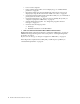
Chapter 1. General checkout The server diagnostic programs are stored in upgradable read-only memory (ROM) on the system board. These programs are the primary method of testing the major components of the server: the system board, Ethernet controller, video controller, RAM, keyboard, mouse (pointing device), diskette drive, serial ports, and hard drives. You can also use them to test some external devices. See “Diagnostic programs and error messages” on page 15.
• • • • • • • Power-on the computer. If the computer hangs and no error is displayed, go to “Undetermined problems” on page 98. Record any POST error messages displayed on the screen. If an error is displayed, look up the first error in the “POST error codes” on page 90. Check the information LED panel System Error LED; if on, see “Information panel system error LED” on page 85. Check the System Error Log. If an error was recorded by the system, see “Chapter 7. Symptom-to-FRU index,” on page 83.
Chapter 2. General information The IBM® xSeries 330 server is a one U-high1 rack-model server for highvolume network transaction processing. This high-performance, symmetric multiprocessing (SMP) server is ideally suited for networking environments that require superior microprocessor performance, efficient memory management, flexibility, and reliable data storage. The xSeries 330 server comes with a three-year limited warranty and IBM Server Start Up Support.
Features and specifications The following table provides a summary of the features and specifications for the xSeries 330 server. Table 1. Features and Specifications. Microprocessor: • Intel® Size ® Environment: Pentium III microprocessor with MMX™ technology and SIMD extensions • Height 43.69 mm (1.72") • Depth: 653.29 mm (25.72") • Width: 439.93 mm (17.32") • 256 KB Level-2 cache • • Supports up to two microprocessors Weight: approximately 12.
• Impressive performance using an innovative approach to SMP The server supports up to two Pentium III microprocessors. The server comes with one microprocessor installed; you can install an additional microprocessor to enhance performance and provide SMP capability. • Large system memory The memory bus in the server supports up to 4 gigabytes (GB) of system memory. The memory controller provides error correcting code (ECC) support for up to four industry standard PC133, 3.
• • • • • • • • • • Error codes and messages System error logging Upgradable BIOS, diagnostics, and Advanced System Management Processor code Automatic restart after a power failure Parity checking on the PCI buses CRC checking on the SCSI buses Error checking and correcting (ECC) memory Redundant Ethernet capabilities Light Path Diagnostics™ on the system board Vital Product Data (VPD) on system board, and SCSI backplane Server controls and indicators This section identifies the controls and indicators o
Hard disk drive activity light: Each of the hot-swap drives has a Hard Disk Activity light. When this green LED is flashing, the controller is accessing the drive. CD eject button: Push this button to release a CD from the drive. CD drive activity light: When this light is on, it indicates that the CD-ROM drive is in use.
Power-on light: This green LED lights and stays on when you turn on your server and will blink when the server is in standby mode. This light duplicates the power on light on the front of the server. Ethernet 2 link indicator: This green LED lights when there is an active link connection on the 10BASE-T or 100BASE-TX interface for Ethernet port 2. Ethernet 2 speed indicator: This green LED lights when the speed of the Ethernet LAN connected to Ethernet port 2 is 100 Mbps.
Complete the following steps to turn off the server: 1. Refer to your operating system documentation for the proper procedure to shut down the operating system. Note: Each operating system is different. Some will allow an immediate shutdown, while others require and orderly shut-down procedure. 2. Press the power control button on the front of the server. This will put the server in the stand-by mode. 3. Disconnect the server from the power source.
10 Hardware Maintenance Manual: xSeries 330
Chapter 3. Diagnostics This section provides basic troubleshooting information to help you resolve some common problems that might occur with the server. Diagnostic tools overview The following tools are available to help you identify and resolve hardware-related problems: • POST beep codes, error messages, and error logs The power-on self-test (POST) generates beep codes and messages to indicate successful test completion or the detection of a problem. See “POST” on page 12 for more information.
POST When you turn on the server, it performs a series of tests to check the operation of server components and some of the options installed in the server. This series of tests is called the power-on self-test or POST. If POST finishes without detecting any problems, a single beep sounds and the first screen of your operating system or application program appears. If POST detects a problem, more than one beep sounds and an error message appears on your screen.
Table 2. SCSI messages. SCSI Messages All Description One or more of the following might be causing the problem. • A failing SCSI device (adapter, drive, controller) • An improper SCSI configuration • Duplicate SCSI IDs in the same SCSI chain • An improperly installed SCSI terminator • A defective SCSI terminator • An improperly installed cable • A defective cable Action: Verify that: • The external SCSI devices are turned on. External SCSI devices must be turned on before the server.
To view the LEDs on the system board: 1. Turn off the server and any peripheral devices. 2. Remove the cables. 3. Remove the server from the rack and place it on a flat, non-conductive surface. 4. Remove the server cover (see “Removing the cover” on page 44). Note: Refer to “Working inside a server with power on” on page 42 for instructions and precautions for working in the server with the power on. 5. Press and hold the Light Path Diagnostics (blue) button on the diagnostics panel.
Diagnostic programs and error messages The server diagnostic programs are stored in upgradable read-only memory (ROM) on the system board. These programs are the primary method of testing the major components of the server. Sometimes the first error to occur causes additional errors. In this case, the server displays more than one error message. Always follow the suggested action instructions for the first error message that appears.
Warning This result occurs when a possible problem is reported during the diagnostic test, such as when a device that is to be tested is not installed. Test Specific String This is additional information that you can use to analyze the problem. Starting the diagnostic programs You can press F1 while running the diagnostic programs to obtain Help information. You also can press F1 from within a help screen to obtain online documentation from which you can select different categories.
1. Turn on the server and watch the screen. If the server is on, shut down your operating system and restart the server: 2. When the message F2 for Diagnostics appears, press F2. If a power-on password is set, the server prompts you for it. Type in the appropriate password; then, press Enter. 3. When the Diagnostic Programs screen appears, select Utility from the top of the screen. 4. Select View Test Log from the list that appears; then, follow the instructions on the screen.
Recovering BIOS If the BIOS has become corrupted, such as from a power failure during a flash update, you can recover the BIOS using the BIOS code page jumper and a BIOS flash diskette. Note: You can obtain a BIOS flash diskette from one of the following sources: • Use the ServerGuide program to make a BIOS flash diskette. • Download a BIOS flash diskette from the World Wide Web. Go to http: //www.pc.ibm.com/support/, select IBM Server Support, and make the selections for your server.
8. When prompted as to whether you want to save the current code to a diskette, select N. 9. When prompted to choose a language, select a language (from 0 to 7) and press Enter to accept your choice. 10. Do not reboot your system at this time. 11. Remove the BIOS Flash Diskette from the diskette drive. 12. Turn the server off. 13. Move the jumper on J19 to pins 2 and 3 to return to normal startup mode. 14. Restart the server. The system should start up normally.
Table 4. Ethernet troubleshooting chart. Ethernet controller problem The server stops running when loading device drivers. Suggested Action The PCI BIOS interrupt settings are incorrect. Check the following: • Determine if the interrupt (IRQ) setting assigned to the Ethernet controller is also assigned to another device in the Configuration/Setup Utility program.
Novell NetWare or IntraNetWare server ODI driver teaming messages This section provides explanations of the error messages for the Novell NetWare or IntraNetWare server ODI driver, and suggested actions to resolve each problem. Table 5. NetWare driver messages for the Ethernet controller. Message Description Couldn’t allocate resources Explanation: An unknown error has occurred when trying to allocate needed resources for the AFT Module. Action: • Check the server configuration.
Table 5. NetWare driver messages for the Ethernet controller. Can’t unbind specified slot from AFT group. Make sure that the slot you specified is for the primary adapter in an AFT group. Explanation: The number entered in the unbind command was not the primary adapter in an AFT group. Action: Reissue the unbind command and specify the slot number for the primary adapter. LAN adapter at slot nnnn (Port 0xaa) failed to reset. Check the state of the adapter.
Table 6. NDIS (Windows NT or Windows 2000) driver messages for the Ethernet controller. Error code (hex) 0x0F Description Explanation: Could not allocate enough memory for other structures. Action: 1. From the Windows NT desktop, select Start -> Control Panel -> Networks -> Adapters. 2. Select your IBM Ethernet adapter from the list. 3. Select Properties -> Advanced. 4. Lower the value for the resource named in the message. 0x10 Explanation: Did not find any Ethernet controllers.
Table 7. NDIS (Windows NT or Windows 2000) driver teaming messages for the Ethernet controller. Event ID Type Description 12 Warning Explanation: Team nn. Secondary adapter is deactivated from the Team. Action: Make sure the secondary adapter is functioning properly and that the adapter cable is securely connected to the LAN. 13 Informational Explanation: Team nn. Secondary adapter has rejoined the Team. Action: None. 14 Informational Explanation: Team nn. Secondary adapter link is up.
isolated. If system does not power up from minimal configuration, replace FRUs of minimal configuration one at a time until the problem is isolated. To use this method it is important to know the minimum configuration required for a system to power-up. Replacing the battery When replacing the battery you must replace it with a lithium battery of the same type, from the same manufacturer. To avoid possible danger read and follow the safety statement below.
d. Ensure that the battery clip is touching the base of the battery socket by pressing gently on the clip. 6. Insert the new battery: a. Tilt the battery so that you can insert it into the socket, under the battery clip. b. As you slide it under the battery clip, press the battery down into the socket. 7. Reinstall the server cover and connect the cables. 8. Turn on the server. 9. Start the Configuration/Setup Utility program and set configuration parameters. • Set the system date and time.
Note: The server is not designed to operate in an enclosed environment. The xSeries 300 should not reside behind a glass door in its rack enclosure. For more information on specific temperature error messages, see “Temperature error messages” on page 95. Chapter 3.
28 Hardware Maintenance Manual: xSeries 330
Chapter 4. Configuring the server The following configuration programs are provided with the server: • Configuration/Setup Utility This program is part of the basic input/output system (BIOS) that comes with the server. You can use this program to configure serial and parallel port assignments, change interrupt request (IRQ) settings, change the drive startup sequence, set the date and time, and set passwords. See “Using the Configuration/Setup Utility program” for more information.
IBM Netfinity Setup - © IBM Corporation 1998 Configuration/Setup Utility • System Summary • System Information • Devices and I/O Ports • Date and Time • System Security • Start Options • Advanced Setup • Error Logs Save Settings Restore Settings Load Default Settings Exit Setup Help Exit < ↑ > < ↓ > Move Select Notes: 1. You can press F1 to display Help information for a selected menu item. 2.
Select this choice to view or change the assignments for devices and input/output ports. This choice appears only on the full Configuration/Setup Utility main menu. This choice also allows you to enable or disable the integrated SCSI, and Ethernet controllers. — The default setting is Enable for all the controllers. If you select Disable, the system will not configure the disabled device and the operating system will not see the device. (This is equivalent to unplugging the device.
the administrator and power-on passwords, and allow a power-on password to be changed by the user. See“Using passwords” on page 34 for more information. • Start Options Select this choice to view or change the start options. This choice appears only on the full Configuration/Setup Utility main menu. Start options take effect when you start the server. You can select keyboard operating characteristics, such as the keyboard speed. You also can specify whether the keyboard number lock starts on or off.
Attention: Do not make changes here unless directed to do so by an IBM authorized service representative. — Cache Control Select this choice to enable or disable the microprocessor cache. In addition, you can set the microprocessor cache mode to write-back (WB) or writethrough (WT). Selecting write-back mode will provide the maximum system performance. — PCI Slot/Device Information Select this choice to view and identify system resources used by PCI devices.
Select this choice to cancel your changes and restore the factory settings. • Exit Setup If you have made any changes, the program will prompt you to save the changes or exit without saving the changes. Using passwords The System Security choice appears only on the full Configuration/Setup Utility menu. After you select this choice, you can implement two levels of password protection: power-on password and administrator password.
2. Turn off the server and peripheral devices and disconnect all external cables and power cords; then, remove the cover. See “Removing the cover” on page 44. 3. Toggle switch 8 on switch block 1 on the system board. This clears the power-on password for one boot cycle. Note: This means that you can now start or power-up the server one time without having to use the power-on password.
Using the SCSISelect utility program SCSISelect is a built-in, menu-driven configuration utility program that you can use to: • View the default SCSI IDs • Locate and correct configuration conflicts • Perform a low-level format on a SCSI hard disk The following sections provide the instructions needed to start the SCSISelect Utility and descriptions of the menu choices available.
Select this choice to configure startable device parameters. Before you can make updates, you must know the ID of the device whose parameters you want to configure. — SCSI Device Configuration Select this choice to configure SCSI device parameters. Before you can make updates, you must know the ID of the device whose parameters you want to configure. Note: The Maximum Sync Transfer Rate represents the transfer rate for Ultra SCSI devices. – The transfer rate for Ultra3 SCSI LVD devices is 160.
Note: By default you will have 2 seconds after the prompt appears on the screen to press Ctrl+S. 3. 4. Use the arrow keys or press Enter to select a choice from the menu. • Press Esc to return to the previous menu. • Press the F4 key to exit. Follow the instructions on the screen to change the settings of the selected items; then, press Enter.
Chapter 5. Installing options This chapter provides instructions to help you add options to the server. Some option-removal instructions are provided, in case you need to remove one option to install another. For a list of supported options for the server, see the Server Proven list at: http://www.ibm.com/pc/compat Major components of the xSeries 330 server The following illustration shows the locations of major components in the server.
System board The illustrations in the following sections show the components on the system board. System board options connectors The following illustration identifies the connectors on the system board.
The following table describes the function for each switch. Table 9. Switches 1-8. Switch number Switch description 1 Reserved. 2 Reserved. 3 Reserved. 4 Reserved. 5 Force power-on. The default setting is Off (disabled). 6 Reserved. The default setting is Off. 7 Reserved. The default setting is Off. 8 Bypass power-on password. When toggled to the opposite position, bypasses the power-on password, if one is set, for one boot cycle. See “Setting the password override switch” on page 34.
Before you begin Before you begin to install options in the server, read the following information: • Become familiar with the safety and handling guidelines specified under “Handling electrostatic discharge-sensitive devices” on page 110, and read the safety statements in “Safety information” on page 107. These guidelines will help you work safely while working with the server or options.
Rack installation Do the following to install the server in the rack. Reverse the steps to remove the server from the rack. 1. Lift and place the server on the lower edge of the mounting bracket. 2. Slide the server as far back as it will go. 3. Using the thumb screws on the front of the server; secure the server to the brackets. 4. If you have additional servers to install, repeat steps 1 through 3 for each xSeries 330. 5. Install all external cables and power cords to the servers. Chapter 5.
Removing the cover The following information describes how to remove the cover. Cover release lever Screws Complete the following steps to remove the cover from the server: 1. Review the information in “Before you begin” on page 42. 2. Turn off the server and all attached devices and disconnect all external cables and power cords. 3. Remove the server from the rack (see “Rack installation” on page 43). 4. Remove the two screws from the rear of the server. 5.
PCI slot 2 64 bit 33 MHz (J23) PCI slot 1 64 bit 33 MHz (J10) Adapter considerations Before you install adapters, review the following: • Locate the documentation that comes with the adapter and follow those instructions in addition to the instructions in this chapter. If you need to change the switch settings or jumper settings on your adapter, follow the instructions that come with the adapter. • You can install 32-bit or 64-bit full-length or half-length adapters in the expansion slots.
Installing an adapter Complete the following steps to install an adapter: Attention: When you handle electrostatic discharge (ESD) sensitive devices, take precautions to avoid damage from static electricity. For details on handling these devices, refer to “Handling electrostatic discharge-sensitive devices” on page 110. 1. Review the safety precautions that are listed in “Chapter 9. Related service information,” on page 107. 2.
Adapter card Expansion slot clip Retention latch Tab Expansion slot cover Expansion slot 5. Remove the expansion-slot cover. 6. Refer to the documentation that comes with your adapter for any cabling instructions. Attention: You should route adapter cables before you install the adapter. 7. Set any jumpers or switches as described by the adapter manufacturer. 8. Install the adapter: Note: When installing an adapter into slot 2, skip steps a and d. a.
Attention: Route cables so that they do not block the flow of air from the fans. Note: When installing a ServeRAID adapter remove the cable from the SCSI connector (J4) on the system board and attach it to the ServeRAID adapter. Air flow 10. Install the cover see “Removing the cover” on page 44. 11. Turn on the server. Hard disk drives The server supports two 1-inch (26 mm) slim 3.5-inch low voltage differential (LVD) hard disk drives. If you can hot-swap hard disk drives. Notes: 1.
• Inspect the drive tray for any signs of damage. • Ensure that the drive is installed properly in the tray. • To maintain proper system cooling, do not operate the server for more than two minutes without either a drive or a filler panel installed in each bay. • If your server has a ServeRAID adapter installed; refer to the documentation provided with the ServeRAID adapter for information about adding a drive.
6. Check the hard disk drive status indicators to verify that the hard disk drives are operating properly. (See “Server controls and indicators” on page 6 for the location of the status indicators.) • When the green light flashes rapidly (three flashes per second), the controller is identifying the drive. Replacing a hard disk drive is done in the same manner as installing a new hard disk drive.
Slim filler Filler panel Hard disk drive Drive tray Drive tray handle (in open position) Complete the following steps to install a hot-swap drive in a hot-swap drive bay: Attention: • To maintain proper system cooling, do not operate the server for more than two minutes without either a drive or a filler panel installed for each bay. • When you handle electrostatic discharge sensitive devices (ESD), take precautions to avoid damage from static electricity.
2. To avoid damage to a hard disk drive, do not remove the drive from the hot-swap bay until it has had time to spin down (approximately 30 seconds). Handle the drive carefully. 3. Before you replace a hot-swap drive, make sure it is defective. If you partially or completely remove a good drive instead of a defective one, the server might lose valuable data.
— The green light flashes slowly (one flash per second), the drive is being rebuilt. — The green light flashes rapidly (three flashes per second), the controller is identifying the drive. Memory Adding memory to the server is an easy way to improve system performance. You can increase the amount of memory in the server by installing options called memorymodule kits. Each kit contains one industry-standard, dual-inline memory module (DIMM).
Attention: To avoid breaking the retaining clips or damaging the DIMM connectors, handle the clips gently. 5. Install the DIMM in the connector. Attention: To prevent damage to the DIMM connectors do not force the memory module into the connector. a. Turn the DIMM so that the index slots align correctly with the connector. Note: The DIMM has two index slots, one in the center and the other on the left half of the DIMMS connector edge. b.
Microprocessor The server comes with one or two microprocessors installed on the system board. If you have two, or had one and you installed a second microprocessor, the server can operate as a symmetric multiprocessing (SMP) server. With SMP, certain operating systems and application programs can distribute the processing load between the microprocessors. This enhances performance for database and point-of-sale applications, integrated manufacturing solutions, and other applications. Notes: 1.
Installing the microprocessor Complete the following steps to install an additional microprocessor: Attention: When you handle electrostatic discharge-sensitive devices (ESD), take precautions to avoid damage from static electricity. For details on handling these devices, refer to the following Web site and use a search term of ESD: http://www.ibm.com/ 1. Review the safety precautions listed in “Safety information” on page 107. 2.
6. Push the microprocessor release lever down to lock the microprocessor into place. 7. Install the heat sink on the microprocessor: a. Peel the plastic protective strip off the bottom of the heat sink. Make sure the square of thermal material is still on the bottom of the heat sink. b. Align and place the heat sink on top of the microprocessor. Note: Locate the slot in the channel of the heat sink. Orientate the heat sink so the slot will be at the rear of the server. c.
Note: It is very important to replace the clear shield. Slot Heatsink release lever Clip Heatsink Top view of heatsink Microprocessor Terminator card 5. To remove microprocessor #1: a. Remove the adapter board retainer latch: 1) Lift up on the release latch. 2) Remove the screws and put them in a safe place. 3) Lift the retainer latch up and off the system board. b. Follow steps a on page 57 through d on page 57. c.
Slot Heatsink release lever Clip Heatsink Top view of heatsink Microprocessor Retainer clip Terminator card Fan assembly replacement The server comes with six replaceable fans. Attention: Replace a fan that has failed within 48 hours to help ensure proper cooling. The following illustration shows the replacement of a fan. Note: The illustrations in this document might differ slightly from your hardware. Air flow Complete the following steps to replace the fan assembly: Chapter 5.
1. Review the safety precautions listed in “Safety information” on page 107. 2. Turn off the server and peripherals; disconnect cables and cords. 3. Remove the cover. See “Removing the cover” on page 44 for details. 4. Determine which fan to replace by checking the LED at each fan; a lit LED indicates the fan to replace. See “Identifying problems using status LEDs” on page 13.
Installing the cover The following information describes the cover installation procedure. Screws To install the server cover: 1. Clear any cables that might impede the replacement of the clear shield or the cover. 2. Install the clear shield, if it was removed. Note: Thermal considerations require that the clear shield be installed before operating the server. 3. Install the cover by placing it into position and sliding it forward.
Ethernet 1 RS-485 (Advanced System Management Interconnect) A PCI slot 1 PCI slot 2 USB 2 Ethernet 2 C2T out USB 1 RS-485 (Advanced System Management Interconnect) B C2T in Serial port Input/Output ports This section provides information about the input/output (I/O) ports on the server.
2. When the message Press F1 for Configuration/Setup appears, press F1. 3. From the main menu, select Devices and I/O Ports; then, press Enter. Note: The Devices and I/O Ports choice appears only on the full configuration menu. If you set two levels of passwords, you must enter the administrator password to access the full configuration menu. 4. Select the serial port; then, use the arrow keys to advance through the settings available. 5.
The following table shows the pin-number assignments for the USB-port connectors on the rear of the server. Table 11. USB-port connector pin-number assignments. Pin Signal 1 VCC 2 -Data 3 +Data 4 Ground Cable Chaining Technology (C2T) ports There are two C2T ports on the rear of the server. (They are labeled IN and OUT.
C2T chaining cable The C2T Chaining cable is designed to prevent the accidental connection of two OUT connectors with physically different connector shells and different color connector covers (Black = OUT, White = IN). C2T breakout cable A keyboard, monitor, and mouse or pointing device are connected to the server through the device breakout cable. The keyboard and mouse cables have icons of a keyboard and a mouse on their respective cable connectors for easy identification. Chapter 5.
Keyboard connector: There is one keyboard connector on the end of the device breakout cable. This connector is identified by the keyboard icon. Note: If you attach a standard (non-USB) keyboard to the keyboard connector, the USB ports and devices will be disabled during the power-on self-test (POST). The following table shows the pin-number assignments for the keyboard connector on the end of the cable. 6 5 4 3 2 1 Table 12. Keyboard-connector (6-pin female) number assignments .
The following table shows the pin-number assignments for the auxiliary-device connector on the end of the cable. 6 5 4 3 2 1 Table 14. Auxiliary or pointing-device-connector (6 pin female) number assignments . Pin Signal 1 Data 2 Not connected 3 Ground 4 +5 V dc 5 Clock 6 Not connected Ethernet ports The server comes with two integrated Ethernet controllers.
traffic associated with it is switched to the redundant (secondary) controller. This switching occurs without any user intervention. When the primary link is restored to an operational state, the Ethernet traffic switches back to the primary Ethernet controller. High Performance Ethernet Modes: Your Ethernet controller supports optional modes, such as teaming, priority packets, and virtual LANs, which provide higher performance and throughput for your server.
Note: IEEE 802.1p tagging increases the size of the packets it tags. Some hubs and switches will not recognize the larger packets and will drop them. Check your hub or switch documentation to see if they support 802.1p. (You can configure the switch to strip the tags from the packets and send it on to the next destination as normal traffic.) If these devices do not support 802.1p or if you are not sure, use High Priority Queue (HPQ) to prioritize network traffic.
1. Create a VLAN on the switch. Use the parameters you assign there to join the VLAN from the server. Refer to your switch documentation for more information. 2. Double-click the Network icon in the Control Panel window. 3. On the Adapters tab, select the adapter you want to be on the VLAN and select Properties. 4. In IBMSet, select Join VLAN. Note that VLANs cannot be assigned to adapters that are already defined to have an adapter teaming option. 5. Enter the VLAN ID and VLAN name.
Working with cables The server has two different cabling schemes, the Advanced System Management bus (ASM) and the Cable Chaining Technology (C2T). The following sections discuss each of these options. While reading about these options, keep in mind that they are independent of each other. Note: Refer to the following illustration to locate the connectors on the back of your server. The ASM connectors on the back of the server are referred to in this book as RS-485 (A) and RS-485 (B).
Note: For more information about the Advanced System Management PCI adapter refer to the documentation that came with the adapter. Connecting the ASM bus The servers in the Advanced System Management bus are referenced by their assigned addresses and not their position in the rack. Complete the following steps to connect the ASM bus: 1. Turn off the servers. 2. Locate the RS-485 ports on the rear of the server and an Ethernet cable with RJ-14 connectors on both ends. 3.
• The C2T numbering is independent of any other server reference. Changing the servers position in the C2T chain will not effect their IP addresses. Note: Operational notes: 1. Server 1 (usually the server at the bottom of the rack) is the server to which you connect the C2T device break out cable. 2. Server 1 must not be turned off (powered down) for the chain to work properly. 3. If server 1 is turned off (powered down) it must be removed from the chain and replaced by the next server in the chain.
3. Turn the servers on and check the operation of the monitor, pointing device, and keyboard with each server. (See “Testing the C2T chain” for testing instructions). 4 In Out 3 In Out 2 Out In 1 Out In Video Mouse Keyboard Note: Write-on adhesive labels have been provided so that you can label the servers position in the rack.
used to identify the failing node (cable or system) consists of reconnecting the chain a node at a time until the failing node is isolated. Cable management Use the cable ties and hook-and-loop straps that are supplied with your server to secure the cables. Note: Do not secure cables too tightly. Over tightening can cause internal damage to cables. Chapter 5.
76 Hardware Maintenance Manual: xSeries 330
Chapter 6. FRU information (service only) Field Replacement Units (FRUs) should be replaced by qualified service personnel only. Note: Read“Safety information” on page 107 and “Before you begin” on page 42. Diskette/CD-ROM drives To remove the diskette/CD-ROM drive: 1. Power off the server. 2. Remove the cover. See “Removing the cover” on page 44. 3. Disconnect the cables for the floppy disk drive and the CD-ROM drive from the system board. 4. Remove the fans.
Diskette/CD-ROM drive bracket Slim adapter board Diskette drive Bracket Diskette drive retaining wire Metal tab CD-ROM drive retaining wire CD-ROM drive To remove the diskette/CD-ROM drive bracket: Note: Read“Safety information” on page 107 and “Before you begin” on page 42. 1. Remove the diskette/CD-ROM drive. See “Diskette/CD-ROM drives” on page 77. 2. Remove the diskette drive: a.
Hard disk drive backplane To remove the hard disk drive backplane: Note: Read“Safety information” on page 107 and “Before you begin” on page 42. 1. Power off the server. 2. Remove the cover. See “Removing the cover” on page 44. 3. Disconnect the backplane cable from the system board. 4. Pull out the hard drives in order to disconnect them from the backplane. 5. Remove the screw from the top of the backplane bracket. 6. Gently but firmly lift the backplane bracket and board up from the chassis.
2. Remove the cover. See “Removing the cover” on page 44. 3. Disconnect the cables that connect the power supply to the system board. 4. Remove the screws (2) from the side of the chassis. 5. Remove the screws at the back of the chassis and power supply. 6. Slide the power supply away from the side of the chassis and lift up to remove. PCI riser card To remove the PCI riser card: Note: Read“Safety information” on page 107 and “Before you begin” on page 42. 1. Power off the server. 2.
4. Remove the adapter retaining latch (see “Removing a microprocessor” on page 57). 5. Remove the microprocessors. See “Removing a microprocessor” on page 57. 6. Remove the memory modules. See “Installing memory modules” on page 53. 7. Remove screws from the system board. 8. Remove the four screws from the rear of the server. 9. Pull up on the system board to remove from the chassis. Chapter 6.
82 Hardware Maintenance Manual: xSeries 330
Chapter 7. Symptom-to-FRU index This index supports Netfinity 4100R servers. The Symptom-to-FRU lists symptoms, errors, and the possible causes. The most likely cause is listed first. Use this Symptom-to-FRU index to help you decide which FRUs to have available when servicing the computer. The POST BIOS displays POST error codes and messages on the screen. Beep symptoms Beep symptoms are short tones or a series of short tones separated by pauses (intervals without sound). See the following examples.
Beep/Symptom FRU/Action 2-1-1 (Secondary DMA register failed) 1. System Board 2-1-2 (Primary DMA register failed) 1. System Board 2-1-3 (Primary interrupt mask register failed) 1. System Board 2-1-4 (Secondary interrupt mask register failed) 1. System Board 2-2-2 (Keyboard controller failed) 1. Keyboard 2. System Board 2-2-3 (CMOS power failure and checksum checks failed) 1. Battery 2. System Board 2-2-4 (CMOS configuration information validation failed) 1. Battery 2.
Beep/Symptom FRU/Action 3-3-3 (No operational memory in system) 1. Install or reseat the memory modules, then do a 3 boot reset. (See “Using the Configuration/Setup Utility program” on page 29) 2. DIMMs 3. System Board Two Short Beeps (Information only, the configuration has changed) 1. Run Diagnostics 2. Run Configuration/Setup Three Short Beeps 1. DIMM 2. System Board 1. Processor 2. Optional Processor (if installed) 3. System Board 1. Keyboard 2. System Board 1.
2. 3. Check the System Error Log for additional information before replacing a FRU. The DIMM error LEDs, processor error LEDs, and VRM error LEDs turn off when the system is powered down. Diagnostic Panel LED All LEDs off (Check System Error Log for error condition, then clear System Error Log when the problem is found.) FRU/Action 1. System Error Log is 75% full; clear the log. 2.
Diagnostic error codes Note: In the following error codes, if XXX is 000, 195, or 197 do not replace a FRU. The description for these error codes are: 000 The test passed. 195 The Esc key was pressed to abort the test. 197 This is a warning error and may not indicate a hardware failure. For all error codes, replace/follow the FRU/Action indicated. Error Code/Symptom 001-XXX-000 001-XXX-001 (Failed core tests) (Failed core tests) FRU/Action 1. System Board 1.
Error Code/Symptom FRU/Action 035-253-S99 (RAID adapter initialization failure) 089-XXX-001 test) (Failed Microprocessor 089-XXX-002 Optional Microprocessor test) 165-XXX-000 test) (Failed (Failed Service Processor 180-XXX-000 (Diagnostics LED failure) 1. ServeRAID Adapter in slot S is not configured properly. Obtain the basic and extended configuration status and refer to the ServeRAID Hardware Maintenance Manual for more information. 2. Cable 3. SCSI Backplane 4. Adapter 1.
Error Code/Symptom (Failed BIOS Fixed Disk FRU/Action 1. Fixed Disk 2 2. System Board 1. Tape Cartridge, if user executed the Read/Write Tape Drive test (failure code of XXX = 256) 2. SCSI or Power Cable connected to tape drive with SCSI ID NN. 3. Tape Drive with SCSI ID NN. (Refer to the Help and Service Information appendix of the tape drive’s User Guide.) 4. System Board or SCSI Controller. (Run SCSI Controller Diagnostic to determine if the SCSI bus is functioning properly.) 1.
Error Symptom Power switch does not work and reset button does work. (SW 1-5 is force poweron switch.) Diskette drive in-use light stays on, or the system bypasses the diskette drive, or the diskette drive does not work FRU/Action 1. Reseat connector 2. Switch Card 3. System Board 1. If there is a diskette in the drive, verify that: a. The diskette drive is enabled in the Configuration/Setup utility program. b. The diskette is good and not damaged. (Try another diskette if you have one.) c.
Error Code/Symptom 129 (Internal cache error) 151 161 162 Note: 163 1. Processor 2. Optional Processor (if installed) 3. System Board. 1. Run Diagnostics 2. Battery 3. System Board 1. Run Configuration/Setup 2. Battery 3. System Board (Device Configuration Error) 1. Run Configuration/Setup Be sure to load the default settings and any additional desired settings; then, save the configuration. 2. Battery 3. Failing Device 4. System Board 1. Run Configuration/Setup 2.
Error Code/Symptom 201 (Memory test error, see "Memory Settings" on page 33.) If the server does not have the latest level of BIOS installed, update the BIOS to the latest level and run the diagnostic program again. FRU/Action 1. DIMM 2. System Board 1. Processor 2. Optional Processor (if installed) 1. Run configuration / setup 2. Battery 3. System Board 1. Run Configuration/Setup, if disabled by user 2. Disabled DIMM, if not disabled by user. 3. System Board.
Error Code/Symptom 0001200 error) (Machine check architecture 1600 (The Service Processor is not functioning) Do the following before replacing a FRU: 1601 (The system is able to communicate to the Service Processor, but the Service Processor failed to respond at the start of POST.) FRU/Action 1. Processor 1 2. Optional Processor 2 3. System Board. 1. Do the following before replacing a FRU: a. Ensure that a jumper is not installed on J28. b.
Error Code/Symptom (IDE CD-ROM configuration FRU/Action 1. Run Configuration/Setup 2. CD-ROM Drive 3. CD-ROM Power Cable 4. IDE Cable 5. System Board 6. Battery 1. Pointing Device 2. System Board 00019501 (Processor 1 is not functioning - check VRM and processor LEDs) 1. Processor 1 2. System Board 00019502 (Processor 2 is not functioning check VRM and processor LEDs) 1. Processor 2 2. System Board 1. Processor 1 2. System Board 1. Processor 2 2. System Board 1.
Error Code/Symptom 01298101 processor 1) (Bad update data for 01298102 processor 2) (Bad update data for I9990301 (Fixed boot sector error) I9990305 (Fixed boot sector error, no operating system installed) I9990650 restored) (AC power has been FRU/Action 1. Ensure all processors are the same stepping level and cache size. 2. Processor 1 1. Ensure all processors are the same stepping level and cache size. 2. Processor 2 1. Hard Disk Drive 2. Cable 3. SCSI Backplane 4. System Board 1.
Message Action DASD 1 Over Temperature (level-critical; sensor for DASD1 reported temperature over recommended range) 1. Ensure system is being properly cooled; see “Temperature checkout” on page 26. Power Supply "X" Temperature Fault (level-critical; power supply "x" had over temperature condition) 1. Ensure system is being properly cooled; see “Temperature checkout” on page 26. 2.
Message Action System shutoff due to "X" V over voltage (level-critical; system shutoff due to "X" supply over voltage) 1. Check power supply connectors 2. Replace power supply System shutoff due to "X" V under voltage (level-critical system shutoff due to "X" supply under voltage) 1. Check power supply connectors 2. Replace power supply System shutoff due to VRM "X" over voltage 1. Replace power supply Temperature related system shutdown Message Action 1.
Message Action Failure reading I2C device. Check devices on bus 1. 1. Front Panel 2. Replace system board Failure reading I2C device. Check devices on bus 2. 1. Replace DASD backplane 2. Replace system board Failure reading I2C device. Check devices on bus 3. 1. Replace system board Failure reading I2C device. Check devices on bus 4. 1. Replace DIMM 2.
4) Power-on system. If problem remains, suspect the following FRUs in the order listed: a) Power supply b) System board If problem goes away, replace removed items one at a time until failing item is found (power-on and reconfigure system each time). Notes: 1. If the problem goes away when you remove an adapter from the system, and replacing that adapter does not correct the problem, suspect the System Board. 2.
100 Hardware Maintenance Manual: xSeries 330
Chapter 8. Parts listing System The xSeries 330 Parts Listing supports the following models: 11Y, 31Y. 1 18 2 17 3 4 16 5 15 6 7 8 14 9 10 13 12 © Copyright IBM Corp.
Index 102 System Part (Model Number) FRU Number 1 Bracket/Baffle (All Models) 00N6993 2 Heat Sink/Clip Assembly (All Models) 00N6987 3 Terminator Card (All Models) 09N8007 4 Fan with Connector (All Models) 00N6991 5 3.5 Floppy Disk Drive, 12.
Index System Part (Model Number) FRU Number 9.1GB 7200rpm Ultra 160 SCSI (All Models) (optional) 19K1461 18.2GB 7200rpm Ultra 160 SCSI (All Models) (optional) 19K1463 9.1GB 10Krpm Ultra 160 SCSI (All Models) (optional) 19K1465 18.2GB 10Krpm Ultra 160 SCSI (All Models) (optional) 19K1467 36.4GB 10Krpm Ultra 160 SCSI (All Models) (optional) 19K1469 Keyboards Keyboard FRU No.
Keyboard FRU No. Turkish 37L2579 Turkish 37L2580 UK English 37L2581 Yugosl/Lat 37L2582 US English-EMEA 37L2583 Chinese/US 37L2585 Thailand 37L2587 French Canadian 37L0913 Power cords Power cord 104 FRU No.
Power cord United States of America FRU No. 6952301 (110) 1838574 (220) 36L8886 (220V/15A) Chapter 8.
106 Hardware Maintenance Manual: xSeries 330
Chapter 9. Related service information Note: The service procedures are designed to help you isolate problems. They are written with the assumption that you have model-specific training on all computers, or that are familiar with the computers, functions, terminology, and service information provided in this manual. Safety information The following section contains the safety information that you need to be familiar with before servicing an IBM mobile computer.
• Reinstall all covers correctly before returning the machine to the customer. Electrical safety CAUTION: Electrical current from power, telephone, and communication cables can be hazardous. To avoid personal injury or equipment damage, disconnect the attached power cords, telecommunication systems, networks, and modems before you open the server covers, unless instructed otherwise in the installation and configuration procedures. Observe the following rules when working on electrical equipment.
Observe the special safety precautions when you work with very high voltages; these instructions are in the safety sections of maintenance information. Use extreme care when measuring high voltages. • Regularly inspect and maintain your electrical hand tools for safe operational condition. • Do not use worn or broken tools and testers. • Never assume that power has been disconnected from a circuit. First, check that it has been powered-off.
3. Check the power cord for: a. A third-wire ground connector in good condition. Use a meter to measure third-wire ground continuity for 0.1 ohm or less between the external ground pin and frame ground. b. The power cord should be the appropriate type as specified in the parts listings. c. Insulation must not be frayed or worn. 4. Remove the cover. 5. Check for any obvious non-IBM alterations. Use good judgment as to the safety of any non-IBM alterations. 6.
Grounding requirements Electrical grounding of the computer is required for operator safety and correct system function. Proper grounding of the electrical outlet can be verified by a certified electrician.
• Connect and disconnect cables as described in the following table when installing, moving, or opening covers on this product or attached devices. To Connect • To Disconnect 1. Turn everything OFF. 1. Turn everything OFF. 2. First, attach all cables to devices. 2. First, remove power cords from outlet. 3. Attach signal cables to connectors. 3. Remove signal cables from connectors. 4. Attach power cords to outlet. 4. Remove all cables from devices. 5. Turn device ON.
DANGER Some laser products contain an embedded Class 3A or Class 3B laser diode. Note the following: Laser radiation when open. Do not stare into the beam, do not view directly with optical instruments, and avoid direct exposure to the beam. • Statement 4 ≥18 kg (37 lbs) ≥32 kg (70.5 lbs) ≥55 kg (121.2 lbs) CAUTION: Use safe practices when lifting.
• Statement 10 CAUTION: Do not place any object weighing more than 82 kg (180 lbs.) on top of rack-mounted devices.
Importante: Todas as instruções de cuidado e perigo da Server Library começam com um número. Este número é utilizado para fazer referência cruzada de uma instrução de cuidado ou perigo no idioma inglês com as versões traduzidas das instruções de cuidado ou perigo encontradas nesta seção. Por exemplo, se uma instrução de cuidado é iniciada com o número 1, as traduções para aquela instrução de cuidado aparecem nesta seção sob a instrução 1.
Para Conectar: Para Desconectar: 1. DESLIGUE Tudo. 1. DESLIGUE Tudo. 2. Primeiramente, conecte todos os cabos aos dispositivos. 2. Primeiramente, remova os cabos de alimentação das tomadas. 3. Conecte os cabos de sinal aos conectores. 3. Remova os cabos de sinal dos conectores. 4. 4. Conecte os cabos de alimentação às tomadas. Remova todos os cabos dos dispositivos. 5. LIGUE os dispositivos.
• Não remova as tampas. A remoção das tampas de um produto a laser pode resultar em exposição prejudicial à radiação de laser. Nenhuma peça localizada no interior do dispositivo pode ser consertada. • A utilização de controles ou ajustes ou a execução de procedimentos diferentes dos especificados aqui pode resultar em exposição prejudicial à radiação. PERIGO Alguns produtos a laser contêm um diodo laser da Classe 3A ou Classe 3B embutido. Observe o seguinte: Radiação de laser quando aberto.
2 1 CUIDADO: Instrução 10 CUIDADO: Não coloque nenhum objeto com peso superior a 82 kg (180 lbs.) sobre dispositivos montados em rack.
Chapter 9.
120 Hardware Maintenance Manual: xSeries 330
Chapter 9.
122 Hardware Maintenance Manual: xSeries 330
Chapter 9.
124 Hardware Maintenance Manual: xSeries 330
Chapter 9.
126 Hardware Maintenance Manual: xSeries 330
Important: Toutes les consignes Attention et Danger indiquées dans la bibliothèque Server sont précédées d'un numéro. Ce dernier permet de mettre en correspondance la consigne en anglais avec ses versions traduites dans la présente section. Par exemple, si une consigne de type Attention est précédée du chiffre 1, ses traductions sont également précédées du chiffre 1 dans la présente section.
Connexion Déconnexion 1. Mettez les unités hors tension. 1. Mettez les unités hors tension. 2. Commencez par brancher tous les cordons sur les unités. 2. Débranchez les cordons d'alimentation des prises. 3. Branchez les câbles d'interface sur des connecteurs. 3. Débranchez les câbles d'interface des connecteurs. 4. Branchez les cordons d'alimentation sur des prises. 4. Débranchez tous les câbles des unités. 5. Mettez les unités sous tension.
• Pour éviter tout risque d'exposition au rayon laser, respectez les consignes de réglage et d'utilisation des commandes, ainsi que les procédures décrites dans le présent document. DANGER Certains produits laser contiennent une diode laser de classe 3A ou 3B. Prenez connaissance des informations suivantes: Rayonnement laser lorsque le carter est ouvert. évitez de regarder fixement le faisceau ou de l'observer à l'aide d'instruments optiques. évitez une exposition directe au rayon.
2 1 Notice n° 10 ATTENTION: Ne posez pas d'objet dont le poids dépasse 82 kg sur les unités montées en armoire.
Wichtig: Alle Sicherheitshinweise in dieser Server-Bibliothek beginnen mit einer Nummer. Diese Nummer verweist auf einen englischen Sicherheitshinweis mit den übersetzten Versionen dieses Hinweises in diesem Abschnitt. Wenn z. B. ein Sicherheitshinweis mit der Nummer 1 beginnt, so erscheint die übersetzung für diesen Sicherheitshinweis in diesem Abschnitt unter dem Hinweis 1. Lesen Sie alle Sicherheitshinweise, bevor Sie eine Anweisung ausführen.
Kabel anschlieβen: 1. Alle Geräte ausschalten und Netzstecker ziehen. 2. Zuerst alle Kabel an Einheiten anschließen. 3. Signalkabel an Anschlußbuchsen anschließen. 4. Netzstecker an Steckdose anschließen. 5. Gerät einschalten. Kabel lösen: 1. Alle Geräte ausschalten. 2. Zuerst Netzstecker von Steckdose lösen. 3. Signalkabel von Anschlußbuchsen lösen. 4. Alle Kabel von Einheiten lösen.
• Steuer- und Einstellelemente sowie Verfahren nur entsprechend den Anweisungen im vorliegenden Handbuch einsetzen. Andernfalls kann gefährliche Laserstrahlung auftreten. VORSICHT Manche CD-ROM-Laufwerke enthalten eine eingebaute Laserdiode der Klasse 3A oder 3B. Die nachfolgend aufgeführten Punkte beachten. Laserstrahlung bei geöffneter Tür. Niemals direkt in den Laserstrahl sehen, nicht direkt mit optischen Instrumenten betrachten und den Strahlungsbereich meiden.
2 1 Hinweis 10 ACHTUNG: Keine Gegenstände, die mehr als 82 kg wiegen, auf Rack-Einheiten ablegen.
Importante: Tutti gli avvisi di attenzione e di pericolo riportati nella pubblicazione Server Library iniziano con un numero. Questo numero viene utilizzato per confrontare avvisi di attenzione o di pericolo in inglese con le versioni tradotte riportate in questa sezione. Ad esempio, se un avviso di attenzione inizia con il numero 1, la relativa versione tradotta è presente in questa sezione con la stessa numerazione.
Per collegare: Per scollegare: 1. SPEGNERE tutti i dispositivi. 1. SPEGNERE tutti i dispositivi. 2. Collegare prima tutti i cavi alle unità. 2. 3. Collegare i cavi di segnale ai connettori. Rimuovere prima i cavi di alimentazione dalle prese elettriche. 3. Collegare i cavi di alimentazione alle prese elettriche. Rimuovere i cavi di segnale dai connettori. 4. Rimuovere tutti i cavi dalle unità. 4. 5. ACCENDERE le unità.
• Non rimuovere i coperchi. L'apertura dei coperchi di prodotti laser può determinare l'esposizione a radiazioni laser pericolose. All'interno delle unità non vi sono parti su cui effettuare l'assistenza tecnica. • L'utilizzo di controlli, regolazioni o l'esecuzione di procedure non descritti nel presente manuale possono provocare l'esposizione a radiazioni pericolose. PERICOLO Alcuni prodotti laser contengono all'interno un diodo laser di Classe 3A o Classe 3B.
2 1 Avviso 10 ATTENZIONE: Non poggiare oggetti che pesano più di 82 kg sulla parte superiore delle unità montate in rack.
Chapter 9.
140 Hardware Maintenance Manual: xSeries 330
Chapter 9.
Importante: Todas las declaraciones de precauciín de esta Biblioteca del servidor empiezan con un número. Dicho número se emplea para establecer una referencia cruzada de una declaraciín de precauciín o peligro en inglés con las versiones traducidas que de dichas declaraciones pueden encontrarse en esta secciín. Por ejemplo, si una declaraciín de peligro empieza con el número 1, las traducciones de esta declaraciín de precauciín aparecen en esta secciín bajo Declaraciín 1.
Para la conexin Para la desconexiín 1. APÁGUELO todo. 1. APÁGUELO todo. 2. En primer lugar, conecte los cables a los dispositivos. 2. 3. Conecte los cables de señal a los conectores. En primer lugar, retire cada cable de alimentaciín de la toma de alimentaciín. 3. Retire los cables de señal de los conectores. 4. Retire los cables de los dispositivos. 4. 5. Conecte cada cable de alimentaciín a la toma de alimentaciín. ENCIENDA el dispositivo.
• No retire las cubiertas. Si retira las cubiertas del producto láser, puede quedar expuesto a radiaciín láser perjudicial. Dentro del dispositivo no existe ninguna pieza que requiera mantenimiento. • El uso de controles o ajustes o la realizaciín de procedimientos que no sean los que se han especificado aquí pueden dar como resultado una exposiciín perjudicial a las radiaciones. PELIGRO Algunos productos láser contienen un diodo de láser incorporado de Clase 3A o de Clase 3B.
2 1 Declaración 10 PRECAUCIÓN: No coloque ningún objeto que pese más de 82 kg (180 libras) encima de los dispositivos montados en bastidor. Chapter 9.
Send us your comments! We want to know your opinion about this manual (part number 06P1796). Your input will help us to improve our publications. Please photocopy this survey, complete it, and then fax it to IBM HMM Survey at 919-543-8167 (USA). Name: _________________________________________ Phone number: __________________________________ 1.
Problem determination tips Due to the variety of hardware and software combinations that can be encountered, use the following information to assist you in problem determination. If possible, have this information available when requesting assistance from Service Support and Engineering functions.
service. The evaluation and verification of operation in conjunction with other products, except those expressly designated by IBM, are the responsibility of the user.
IBM@ Part Number: File Number: 06P1796 Printed in the United States of America on recycled paper containing 10% recovered post-consumer fiber.