
Datasheet


Anwendung
Die Temperatursicherung Typ 155 431 kann
bei sachgemäßer Anwendung überall dort
eingesetzt werden, wo eine höchstzulässige
Temperatur nicht überschritten werden darf,
wie z. B. in Bügeleisen, Kaffeemaschinen,
Friteusen etc.
Aufbau und Wirkungsweise
Die Temperatursicherung besitzt einen Schmelz-
loteinsatz, der in direktem Wärmekontakt mit
der Befestigungsfl äche steht. Bei Erreichen der
vorbestimmten Ansprechtemperatur schmilzt
das Lot und bewirkt die dauerhafte Öffnung
des Stromkreises. Wiedereinschaltung ist nicht
mehr möglich.
Vorteile
- einfache Montage
- schnelle Wärmeübertragung
- Isolierkörper aus Keramik
- hohe Dauerbetriebstemperatur T
h
- große Kontaktöffnungskraft
- hohe Lebensdauer
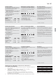
Ausführungen
Die verschiedenen Anschluss- und Befesti-
gungsmöglichkeiten sind auf der Rückseite
dargestellt.
Einbauhinweis
Beim Einbau der Temperatursicherung müssen
die geltenden elektrischen Anforderungen (z. B.
Kriech- und Luftstrecken) nach der jeweiligen
Bestimmung für das Gerät, z. B. DIN VDE
0700 (IEC 60335-1), sowohl unter üblichen
Bedingungen wie auch im Fehlerfall eingehalten
werden. Die Anforderungen des Anwendungs-
hinweises in Anhang der DIN VDE 0821 EN
60 691 sollten berücksichtigt werden. Bei der
Montage der Temperatursicherung in einem
Gerät ist zu beachten:
- Die elektrischen Anschlüsse sind für innere
Verdrahtung vorgesehen;
- Die elektrischen Kontaktteile innerhalb des
Isoliersockels dürfen nicht mit Werkzeugen,
scharfen Gegenständen o. ä. berührt werden,
um mechanische Beschädigungen und damit
Funktionsbeeinträchtigung zu vermeiden.
Application
Properly installed, the thermal link type 155
431 may be used for example in coffeemakers,
irons, fryers etc, and wherever a fi xed tempera-
ture may not be exceeded.
Structure and Function
The thermal link has a melt solder insert in
the mounting plate which is in direct thermal
contact with the surface that is to be moni-
tored. When the preset temperature is reached,
the solder melts causing a pin to move which
results in the electrical contacts opening. Re-
setting is not possible.
Advantages
- easy mounting
- rapid heat transmission
- ceramic housing
- high holding temperature T
h
- high force to open contact
- high durability
Design
Several fi xing arrangements and terminal
variants are described on the back page.
Mounting requirements
During installation compliance with all relevant
electrical requirements must be ensured with
special regard to insulation resistance, dielectric
strength, creepage distances and clearances
both under normal conditions and in case of
a fault, as specifi ed in the relevant equipment
standard, for example DIN VDE 0700 (IEC
60335-1). The requirements in the application
note in the appendix of the DIN VDE 0821 EN
60 691 shall be taken into consideration.
When mounting the thermal link the following
requirements should be observed:
- The terminals shall be used for internal
connections only
- The electrical contacts inside the insulator
must not be touched by any tools or
similar objects to avoid damage and
possible malfunctions.
Application
Après une étude d’implantation le protecteur
thermique type 155 431 peut être utilisé
partout où un appareil nécessite une sécurité
thermique, par exemple les fers à repasser, les
cafetières, les friteuses, etc.
Construction et fonctionnement
Le protecteur thermique possède une partie
fusible qui est en contact direct avec la surface
de fi xation. A la température assignée de
fonctionnement, le fusible fond et les contacts
s’ouvrent durablement. Un réenclenchement
n’est plus possible.
Avantages
- montage simplifi é
- excellente réactivité
- boîtier isolant en céramique
- haute température de maintien T
h
- grande puissance d’ouverture du contact
- longue durée de vie
Versions
Les différentes versions de connexion et de
fi xation fi gurent au verso.
Indications de montage
Lors du montage du protecteur thermique, les
exigences électriques en vigueur doivent être
respectées selon la destination du protecteur,
propre à chaque appareil, par exemple en fonc-
tion de la norme DIN VDE 0700 (IEC 60335-1)
aussi bien dans les conditions de fonctionne-
ment habituel que dans les cas de mauvais
fonctionnement. Les instructions de montage
fi gurant annexe de la norme DIN VDE 0821 EN
60 691 doivent être prises en considération.
Lors de l’installation du protecteur dans l’appareil
il vous faudra tenir compte des points suivants:
- les connexions électriques sont prévues pour
un câblage interne;
- les contacts électriques à l’intérieur du socle
isolant ne doivent pas être en relation avec
des instruments, des objects tranchants, afi n
d’éviter un endommagement mécanique et
par là-même une détérioration de la fonction.
Die von uns genannten technischen Daten wurden von uns unter La-
borbedingungen nach allgemein gültigen Prüfvorschriften, insbeson-
dere DIN EN-Vorschriften ermittelt. Nur insoweit werden Eigenschaften
zugesichert. Die Prüfung der Eignung für den vom Auftraggeber vor-
gesehenen Verwendungszweck bzw. den Einsatz unter Gebrauchs-
bedingungen obliegt dem Auftraggeber; hierfür übernehmen wir keine
Gewährleistung. Änderungen vorbehalten.
The above mentioned technical data was determined under laboratory
conditions in accordance with the relevant test regulations, in particular
DIN EN Standards. The data shown is guaranteed in this respect only.
It is the responsibility of the customer to ensure suitability for the pro-
posed application or for operating according to conditions of use. We
can offer no warranty in this respect. Subject to change without notice.
Les données techniques que nous indiquons ont été déterminées dans
les conditions de laboratoire et suivant les prescriptions valables en gé-
néral, notamment les normes DIN EN. Les propriétés garanties ne le
sont que dans ce cadre. C‘est au client d‘examiner si ces instruments
conviennent à son utilisation prévue ou à l‘application selon les condi-
tions de leur mise en œuvre: En ce qui concerne ce point, nous n‘assu-
mons aucune garantie.