NVS User’s Manual Version 1.2.
Table of Contents 1 FEATURES AND SPECIFICATIONS ................................................................. 1 1.1 Overview .......................................................................................................................................... 1 1.2 Features ........................................................................................................................................... 1 1.3 Specifications .............................................................
4.1.2 Shutdown ................................................................................................................................... 18 4.1.3 Auto Resume after Power Failure ............................................................................................ 18 4.1.4 Replace Button Battery ............................................................................................................. 19 4.2 Record.....................................................................
APPENDIX B COMPATIBLE BACKUP DEVICE LIST ........................................ 81 APPENDIX C COMPATIBLE CD/DVD DEVICE LIST ............................................. 85 APPENDIX D COMPATIBLE DISPLAYER LIST .................................................. 86 APPENDIX E COMPATIBLE SWITCHER LIST .................................................... 87 APPENDIX F COMPATIBLE WIRELESS MOUSE LIST ...................................... 88 APPENDIX G EARTHING ................................................
Welcome Thank you for purchasing our NVS! This user’s manual is designed to be a reference tool for the installation and operation of your system. Here you can find hardware installation, cable connection information and general operations; also here you can find web operation instruction.
Important Safeguards and Warnings 1.Electrical safety All installation and operation here should conform to your local electrical safety codes. We assume no liability or responsibility for all the fires or electrical shock caused by improper handling or installation. 2.Transportation security Heavy stress, violent vibration or water splash are not allowed during transportation, storage and installation. 3.Installation Keep upwards. Handle with care.
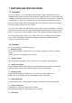
1 FEATURES AND SPECIFICATIONS 1.1 Overview This series product is an excellent digital monitor product. It adopts embedded Linux OS to maintain reliable operation. Popular H.264 compression algorithm and G.711 audio compression technology realize high quality, low bit stream. Unique frame by frame play function is suitable for detailed analysis. It has various functions such as record, playback, monitor at the same time and can guarantee audio video synchronization.
Support PTZ decoder via RS485. Support various decode protocols to allow the PTZ to control the speed dome. Slight function differences may be found due to different series. 1.
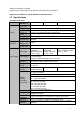
Information Color Configuration Image Quality Audio Audio Audio Input Audio Output Bidirectional Audio Audio Talk Storage Function Backup Mode Screen-lock function to prevent unauthorized user seeing secret video. Channel name, recording status, screen lock status, video loss status and motion detection status are shown on the bottom left of display screen. Hue, brightness, contrast, saturation and gain setup for each channel.
Password Authentication Upgrade Login, Logout and Shutdown Environmental Power Power Consumption Working Temperature Working Humidity atmospheric pressure Dimension (W*D*H) Weight Installation Mode Integrated management for local user, serial port user and network user. Configurable user power. Support account /group and its corresponding rights modification. No limit to the user or group amount. Password modification Administrator can modify other user’s password.
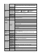
Video Standard Record Speed Video Partition Monitor Touring Resolution (PAL/NTSC ) Image Quality Privacy mask Image Information Storage Function Network Function 1 windows(Optional) 1/2 windows 1/4 windows Support monitor tour functions such as alarm, motion detection, and schedule auto control.
Motion Detection and Alarm Interface Motion Detection Video Loss USB Interface Network connection RS485 System Information Antenna Interface Hard Disk Information Data Stream Statistics Log statistics Version On-line user User Management User Manageme nt Password Authenticati on Upgrade Login, Logout and Shutdown General Parameter Power Power Consumptio n Working Temperatur e Working Humidity Air Pressure Dimension (W*D*H) Weight Support network PTZ lens control File download backup and playback Mu
Installation Mode Desktop installation 7
2 Overview and Controls This section provides information about front panel and rear panel. When you install this series NVS for the first time, please refer to this part first. 2.1 Front Panel 2.1.1 SD backup series Figure 2-1 Please refer to the following sheet for detailed information.
Icon Name Reset Reset Color Function Back to factory mode after pressing the button for 3 seconds. IR Reserved. 2.1.2 HDD backup series Figure 2-2 Please refer to the following sheet for detailed information. Icon Name Function Network status indication light Power status indication light HDD status indication light The red light becomes on when the network connection is not proper. The red light is on when the power connection is proper. The red light is on when the HDD malfunction occurred. 2.
Name Connector Function SD SD card port Insert SD card. 1/2/3/4 Alarm Input Port 1~4 Alarm input port, receive signal from external alarm. G Ground Shared ground end. NO/C-1 2ch alarm output Output alarm signal to the alarm device. NO/C-1: NO alarm output 1 NO/C-2: NO alarm output 2 NO/C-2 A, B You can connect to the control devices such as speed dome PTZ. ANT To connect wireless antenna in order to receive 3G wireless signal. NET 10M/100M self-adaptive Ethernet interface.
Port Name Connector G Alarm input ground NO/C-1 2ch alarm output NO/C-2 Function Shared ground Output alarm signal to the alarm device. NO/C-1: NO alarm output 1 NO/C-2: NO alarm output 2 A、B RS485 port. You can connect to the control devices such as speed dome PTZ. ANT To connect wireless antenna in order to receive 3G wireless signal NET 10M/100M self-adaptive Ethernet interface 12VDC Input 12V DC POE When supply power via PoE.
Port Name 1~4 NO C A Alarm Input Port 1~4 Function I/O Port Alarm input channel amount is 4 When your alarm input device is using external power, please make sure the device and the NVS have the same ground. Ground end Alarm input ground end. Alarm Output Port1 Output alarm signal to the alarm device. Please make sure there is power to the external alarm device. NO:Normal open alarm output port. C:Alarm output public end. RS485 Port B ANT Connector RS485_A port.
2.3.2 HDD backup series Figure 2-7 2.4 Mouse Control Left click mouse System pops up password input dialogue box if you have not logged in. In real-time monitor mode, you can go to the main menu. When you have selected one menu item, left click mouse to view menu content. Implement the control operation. Modify checkbox or motion detection status.
In input box, you can select input methods. Left click the corresponding button on the panel you can input numeral/English character (small/capitalized). Here ← stands for backspace button. _ stands for space button. In English input mode: _stands for input a backspace icon and ← stands for deleting the previous character. In numeral input mode: _ stands for clear and ← stands for deleting the previous numeral. When input special sign, you can click corresponding numeral in the front panel to input.
3 Installation and Connections Note: All the installation and operations here should conform to your local electric safety rules. 3.1 Check Unpacked NVS When you receive the NVS from the forwarding agent, please check whether there is any visible damage. The protective materials used for the package of the NVS can protect most accidental clashes during transportation. Then you can open the box to check the accessories. Please check the items in accordance with the list on the warranty card.
7. Put the cover in accordance 8. Secure the screws in the with the clip and then place the rear panel and the side panel. upper cover back. Note: You can connect the HDD data cable and the power cable first and then fix the HDD in the device. Please pay attention to the front cover. It adopts the vertical sliding design. You need to push the clip first and then put down. 3.4 Connecting Power Supply Please check input voltage and device power button match or not.
3.5.2 Connecting Video Output Video output includes a BNC(PAL/NTSC BNC(1.0VP- P, 75Ω)output ,and a VGA output. When you are using pc-type monitor to replace the monitor, please pay attention to the following points: To defer aging, do not allow the pc monitor to run for a long time. Regular demagnetization will keep device maintain proper status. Keep it away from strong electromagnetic interference devices. Using TV as video output device is not a reliable substitution method.
4 Overview of Navigation and Controls Important Slight difference may be found in the interface. All the interfaces listed below are based on the 4-channel series product. Before operation, please make sure: You have properly installed HDD and connect all the cable connections. The provided input power and the device power are matched. The external power shall be DC +12V. Always use the stable current, if necessary UPS is a best alternative measure. 4.1 Login, Logout & Main Menu 4.1.
The system can automatically backup video and resume previous working status after power failure. 4.1.4 Replace Button Battery Please make sure to use the same battery model if possible. We recommend replace battery regularly (such as one-year) to guarantee system time accuracy. Note: Before replacement, please save the system setup, otherwise, you may lose the data completely! 4.2 Record 4.2.
Resolution: System supports various resolutions, you can select from the dropdown list. For this model, main stream supports D1 (PAL: 25f/s. NTSC: 30f/s.)/HD1/2CIF/CIF/QCIF. The extra stream supports CIF/QCIF. Please note the resolution may vary due to different channels. Frame rate: It ranges from 1f/s to 25f/s in PAL mode and 1f/s to 30f/s in NTSC mode. Bit rate type: System supports two types: CBR and VBR. In VBR mode, you can set video quality.
Figure 4-4 4.3.1 Snapshot 4.3.1.1 Schedule Snapshot In Encode interface, click snapshot button to input snapshot mode, size, quality and frequency. See Figure 4-5. Figure 4-5 4.3.1.2 Activation Snapshot In Encode interface, click snapshot button to input snapshot mode, size, quality and frequency. See Figure 4-6. After you enabled this function, system can snapshot when the corresponding alarm occurred. Figure 4-6 4.3.1.
Please note the activation snapshot has the higher priority than schedule snapshot. If you have enabled these two types at the same time, system can activate the activation snapshot when an alarm occurs, and otherwise system just operates the schedule snapshot. 4.4 Network Here is for you to input network information. See Figure 4-7. IP address: Here you can input IP address. DHCP: It is to auto search IP. When enable DHCP function, you can not modify IP/Subnet mask /Gateway.
Advanced setup interface is shown as in Figure 4-8. Please draw a circle to enable corresponding function and then double click current item to go to setup interface. Figure 4-8 4.4.1.1 IP Filter IP filter interface is shown as in Figure 4-9. You can add IP in the following list. The list supports max 64 IP addresses. Please note after you enabled this function, only the IP listed below can access current NVS. If you disable this function, all IP addresses can access current NVS. Figure 4-9 4.4.1.
-“D” address space The higher four-bit of the first byte=”1110” Reserved local multiple cast group address -224.0.0.0-224.0.0.255 -TTL=1 When sending out telegraph -For example 224.0.0.1 All systems in the sub-net 224.0.0.2 All routers in the sub-net 224.0.0.4 DVMRP router 224.0.0.5 OSPF router 224.0.0.13 PIMv2 router Administrative scoped addressees -239.0.0.0-239.255.255.
Host IP: Input your PC address. Port: This series NVS supports TCP transmission only. Port default value is 123. Update interval: minimum value is 1. Max value is 65535. (Unit: minute) Time zone: select your corresponding time zone here. Here is a sheet for your time zone setup. City /Region Name Time Zone London GMT+0 Berlin GMT+1 Cairo GMT+2 Moscow GMT+3 New Deli GMT+5 Bangkok GMT+7 Beijing (Hong Kong) GMT+8 Tokyo GMT+9 Sydney GMT+10 Hawaii GMT-10 Alaska GMT-9 Pacific Time(P.
Figure 4-13 Please note NNDS type includes: CN99 DDNS、NO-IP DDNS、Private DDNS、Dyndns DDNS and sysdns DDNS. All the DDNS can be valid at the same time, you can select as you requirement. Private DDNS function shall work with special DDNS server and special Professional Surveillance Software (PSS). 4.4.1.6 Email The email interface is shown as below. See Figure 4-14. SMTP server: Please input your email SMTP server IP here. Port: Please input corresponding port value here.
Figure 4-14 4.4.1.7 FTP You need to download or buy FTP service tool (such as Ser-U FTP SERVER) to establish FTP service. Please install Ser-U FTP SERVER first. From “start” -> “program” -> Serv-U FTP Server -> ServU Administator. Now you can set user password and FTP folder. Please note you need to grant write right to FTP upload user. See Figure 4-15. Figure 4-15 You can use a PC or FTP login tool to test setup is right or not. For example, you can login user ZHY to FTP://10.10.7.
Figure 4-16 System also supports upload multiple NVSs to one FTP server. You can create multiple folders under this FTP. In Figure 4-7, select FTP and then double click mouse. You can see the following interface. See Figure 4-17. Figure 4-17 Please highlight the icon in front of Enable to activate FTP function. Here you can input FTP server address, port and remote directory. When remote directory is null, system automatically create folders according to the IP, time and channel.
and user password. You can adopt default dial setup if the service operator has not provided special account. Figure 4-18 4.4.1.9 Alarm Centre This interface is reserved for you to develop. 4.5 Default Click default icon, system pops up a dialogue box. You can highlight to restore default factory setup. See Figure 4-19. Select all General Encode Schedule RS232 Network Alarm Detect Pan/tilt/zoom Channel name Please highlight icon to select the corresponding function.
Figure 4-19 4.6 TV Adjust Here is for you to adjust TV output setup. See Figure 4-20. Please drag slide bar to adjust each item. After all the setups please click OK button, system goes back to the previous menu.
5 WEB OPERATION Important Slight difference may be found in the interface. All the interfaces listed below are based on the 4channel series product. 5.1 Network Connection Before web operation, please check the following items: Network connection is right NVS and PC network setup is right. Please refer to network setup(main menu->setting>network) Use order ping ***.***.***.***(* NVSIP address) to check connection is OK or not. Usually the return TTL value should be less than 255.
Figure 5-2 After installation, the interface is shown as below. See Figure 5-3. Please input your user name and password. Default factory name is admin and password is admin. Note: For security reasons, please modify your password after you first login. Figure 5-3 After you logged in, you can see the main window. See Figure 5-6. This main window can be divided into the following sections.
Section 1: there are five function buttons: configuration (chapter 5.3), search (chapter 5.4), alarm (chapter 5.5), about (chapter 5.6), log out (chapter 5.7). Section 2: there are channel number and three function buttons: start dialog and local play, refresh. Section3: there are PTZ (chapter 5.2.2), color (chapter 5.2.3) button and you can also select picture path and record path. Section 4:real-time monitor window. Please note current preview window is circled by a green rectangle zone.
In section 2, left click the channel name you want to view, you can see the corresponding video in current window. On the top left corner, you can view device IP, channel number, network monitor bit stream. 1 2 3 Figure 5-7 On the top right corer, there are six unction buttons. See Figure 5-8. 1 2 3 4 5 6 Figure 5-8 1: Digital zoom: Click this button and then left drag the mouse in the zone to zoom in. right click mouse system restores original status.
Please note, the audio input port from the device to the client-end is using the first channel audio input port. During the bidirectional talk process, system will not encode the audio data from the 1channel. Local Play The Web can playback the saved (Extension name is dav) files in the PC-end. Click local play button, system pops up the following interface for you to select local play file. See Figure 5-10. Figure 5-10 5.2.2 PTZ Before PTZ operation, please make sure you have properly set PTZ protocol.
3D Intelligent Positioning Key You can click this icon to display or hide the PTZ control platform. Figure 5-11 5.2.2.1 Direction key and 3D positioning key In Figure 5-11 there are eight direction keys. In the middle of the eight direction keys, there is a 3D intelligent positioning key. Click 3D intelligent positioning key, system goes back to the single screen mode. Drag the mouse in the screen to adjust section size. It can realize PTZ automatically. 5.2.2.2 Speed System supports eight-level speed.
Figure 5-12 5.2.2.4 Auto Scan In Figure 5-12 , move the camera to you desired location and then click left limit button. X439H 439H 439H X Then move the camera again and then click right limit button to set a right limit. 5.2.2.5 Pattern In Figure 5-12, you can input pattern value and then click start record button to begin PTZ movement. Please go back to Figure 5-11 to implement camera operation. Then you can click stop record button. Now you have set one pattern. X440H 440H 440H 5.2.2.
Figure 5-13 5.2.3 Color Click color button in section 3, the interface is shown as in Figure 5-14. Here you can select one channel and then adjust its brightness, contrast, hue and saturation. (Current channel border becomes green). Or you can click default button to use system default setup. Figure 5-14 5.2.4 Picture Path and Record Path Click more button in Figure 5-14 , you can see an interface is shown as in Figure 5-15.
Click the record item; you can see there are two options: DAV/ASF. Click picture path button, you can see an interface is shown as in Figure 5-16. Please click choose button to modify path. Figure 5-16 Click record path button, you can see an interface is shown as in Figure 5-17. Please click choose button to modify path. Figure 5-17 Click reboot button, system pops up the following dialogue box. See Figure 5-18. Please click OK to reboot.
Figure 5-19 5.3.1.2 HDD information Here you can view local storage status, free capacity and total capacity. See Figure 5-20. Figure 5-20 5.3.1.3 Log Here you can view system log. See Figure 5-21.
Figure 5-21 Click backup button, the interface is shown as in Figure 5-22. Figure 5-22 Please refer to the following sheet for log parameter information. Parameter Function Type Log types include: system operation, configuration operation, data management, alarm event, record operation, user management, log clear and file operation. You can select log type from the drop down list and then click search button to view the list. Search Clear You can click this button to delete all displayed log files.
Figure 5-23 Please refer to the following sheet for detailed information. Parameter Function DST Here you can set day night save time begin time and end time. Language You can select the language from the dropdown list. Device needs to reboot to get the modification activated. HDD Full There are two options: stop recording or overwrite the previous files when HDD is full. When current working HDD is overwriting or it is full now, system stops record.
Figure 5-24 Figure 5-25 Figure 5-26 Figure 5-27 43
Please refer to the following sheet for detailed information. Parameter Function Channel Here is for you to select a monitor channel. Channel Name Here is to display current channel name. You can modify it. Compression H.264 Audio/Video For the main stream, recorded file only contains video by default. You need to draw a circle here to enable audio function. For extra stream, you need to draw a circle to select the video first and then select the audio if necessary.
Parameter Function Copy It is a shortcut menu button. You can copy current channel setup to one or more channels. The interface is shown as in Figure 5-28 Save You can click save button after you complete setup for one channel, or you can complete the whole setups and then click save button. Refresh Click this button to get device latest configuration information. Click copy interface, the interface is shown as in Figure 5-28.
Figure 5-30 Please refer to the following sheet for detailed information. Parameter Function Channel Please select a channel first. Pre-record Please input pre-record value here. System can record the three to five seconds video before activating the record operation into the file. (Depends on data size). Setup Copy In Figure 5-29, click set button, you can go to the corresponding setup interface. See Figure 5-30.
Figure 5-31 Please refer to the following sheet for detailed information. Parameter Function Ethernet Please select the network card first. DHCP Dynamically get IP address. You can get the device IP from the DHCP server if you enabled this function. TCP Port Default value is 37777. You can modify if necessary. HTTP Port Default value is 80. Email The email interface is shown as in Figure 5-32. Figure 5-32 Please refer to the following sheet for detailed information.
Parameter Function SMTP Server Input server address and then enable this function. Port Default value is 25. You can modify it if necessary. User Name The sender email account user name. Password The sender email account password. Sender Sender email address. Subject Input email subject here. Address Input receiver email address here. Max input three addresses. DDNS The DDNS interface is shown as in Figure 5-33. Please make sure your NVS support this function.
Parameter Function Password The password you input to log in the server. Interval Device sends out alive signal to the server regularly. You can set interval value between the device and DDNS server here. NAS NAS interface is shown as in Figure 5-34. Please make sure your NVS support this function. Figure 5-34 Please refer to the following sheet for detailed information. Parameter Function NAS enable Please select network storage protocol and then enable NAS function.
Parameter Function Refresh Click this button to get device latest configuration information. NTP The NTP interface is shown as in Figure 5-35. Here you can realize network time synchronization. Please enable current function and then input server IP, port number, time zone and update interval. Please note the SNTP supports TCP transmission only and its port shall be 123.The update interval ranges from 1 to 65535. Default value is 10 minutes.
Alarm Centre Alarm centre interface is shown as below. See Figure 5-36. This interface is for you to develop. The alarm signal can be uploaded to the alarm centre when there is local alarm. Please set the corresponding parameters such as server IP, port and etc. The system can send out the data as the protocol defined to the client-end. Figure 5-36 Advanced The advanced interface is shown as in Figure 5-37. Multiple cast Please refer to chapter 4.4.1.2 for detailed multiple cast setup information.
Figure 5-37 5.3.2.5 Detect Analysis the video, system enable motion detection alarm when it detects the motion signal reached the specified sensitivity. The detection interface is shown as in Figure 5-38.
Please refer to the following sheet for detailed information. Parameter Function Event Type There are three types: Motion detection/video loss/Camera Masking. Channel Select channel name from the dropdown list. Enable You need to draw a circle to enable motion detection function. Sensitivity There are six levels. The sixth level has the highest sensitivity. Region Region: If you select motion detection type, you can click this button to set motion detection zone.
5.3.2.6 PTZ PTZ interface is shown as in Figure 5-40. Please note, before operation please make sure you have set speed dome address. And NVS and speed dome connection is OK. Figure 5-40 Please refer to the following sheet for detailed information. Parameter Function Channel You can select monitor channel from the dropdown list. . Protocol Select the corresponding dome protocol.(such as PELCOD) Address Set corresponding dome address. Default value is 1.
Figure 5-41 Please refer to the following sheet for detailed information. Parameter Function Select All Restore factory default setup. Export Configuration Export system configuration to local PC. Import Configuration Import configuration from PC to the system. 5.3.3 Advanced 5.3.3.1 HDD Management HDD management includes net storage management and local storage management. Please note, if you want to use local storage function, your storage device need to support current function.
Figure 5-42 Please refer to the following sheet for detailed information. Parameter Function Format Clear data in the disk. Read/write Set current SD card as read/write Read only Set current card as read. Recover Recover dada after error occurs. Please note system needs to reboot to activate current setup. 5.3.3.2 Record Record control interface is shown as in Figure 5-43.
Please refer to the following sheet for detailed information. Parameter Function Auto System enables auto record function as you set in record schedule setup. Enable corresponding channel to record no matter what period applied in the record setup. Stop current channel record no matter what period applied in the record setup. Manual Stop 5.3.3.3 Account Here you can add, remove user or modify password. See Figure 5-44. Figure 5-44 5.3.3.3.
Figure 5-45 5.3.3.3.2 Add/Modify Group Click add group button, the interface is shown as below. See Figure 5-46. Here you can input group name and then input some memo information if necessary. There are total 60 rights such as control panel, shut down, real-time monitor, playback, record, record file backup, PTZ, user account, system information view, alarm input/output setup, system setup, log view, clear log, upgrade system, control device and etc.
Figure 5-47 5.3.3.4 Auto Maintenance Here you can select auto reboot and auto delete old files interval from the dropdown list. See Figure 5-48. Figure 5-48 5.3.3.5 Snapshot Snapshot interface is shown as in Figure 5-49.
Figure 5-49 Please refer to the following sheet for detailed information. Parameter Function Channel It is the monitor channel. Snapshot mode There are two modes: Timing and activation. Frame rate You can select from the dropdown list. The value ranges from 1f/s to 7f/s. Resolution You can select from the dropdown list. There are two options: CIF/QCIF. You can select from the dropdown list. Here is for you to set video quality. There are six options: 10%, 30%, 50%, 60%, 80%、100%.
Figure 5-50 Please refer to the following sheet for detailed information. Parameter Function Event Type The abnormal events include: no disk, no space, disk error, net error. You need to draw a circle to enable this function. Latch The alarm output can delay for the specified time after alarm stops. Then system disables alarm and corresponding activation output. The default value is 10s. Send email If you enable this function, system can send out email to alarm the specified user.
Figure 5-51 Auto Register Please refer to the following sheet for detailed information. Parameter Function Enable Enable auto register function. No. Device management server number. IP Device management server IP address. Port Server port number. Device ID Device ID in the device management server. 5.3.4.2 Preferred DNS Here you can set server or local operator DNS address. See Figure 5-52. This function is useful when you input domain name in some item.
Figure 5-52 5.3.4.3 CDMA/GPRS The CDMA/GPRS interface is shown as below. See Figure 5-53.
Figure 5-54 Schedule Setup Please refer to the following sheet for detail information. Parameter Function Wireless type You can select from the dropdown list. Enable Please check the box to enable the selected function. APN Please input the connection name here. Dial/SMS activate state There are two types for the device to connect to the 3G. It includes the dial-up and sms. Dial-up number Please input 3G network dialup number here. Username The user name for you to login the 3G network.
Wireless signal CDMA_1X signal EVDO signal You can view current 3G network signal. After the device connected to the EVDO module,you can view CDMA_1x network signal. After the device connected to the W-CDMA or TD module,you can view the EDGE network signal. You can view current 3G network signal. After the device connected to the EVDO module,you can view EVDO signal. After the device connected to the W-CDMA module,you can view W_CDMA network signal here.
Dial activate The mobile user can give a call to activate the device to connect to the 3G network. You need to check the box to enable current function. Caller You can input several senders’’ mobile number here. Add Click it to add the corresponding mobile phone user. Delete Click it to remove the corresponding mobile phone user. Message type There are two types: SMS and MMS. Right now system supports SMS only. Title You can input message subject here.
Auto connect: System auto connects to the previous hotspot after device reboot or disconnection resulting from the environment factors. Connect: Select a hotspot from the list and then connect. Disconnect: After successfully connected to one hotspot, the connect button becomes disconnect button for you to disconnect. (Note: When the Auto connect function is enabled, device will connect again automatically within a short time.
It is to set hotspot such as DHCP, static IP setup, and connection password setup. 5.4 Search Click search button, you can see an interface is shown as in Figure 5-56. Please select record playback mode, and then select start time, end time and channel. Then please click search button, you can see the corresponding files in the list.
Figure 5-56 Select the file(s) you want to download and then click download button, system pops up a dialogue box shown as in Figure 5-57, and then you can specify file name and path to download the file(s) to your local pc. Figure 5-57 Now you can see system begins download and the download button becomes stop button. You can click it to terminate current operation. At the bottom of the interface, there is a process bar for your reference. See Figure 5-58.
Figure 5-58 When download completed, you can see a dialogue box shown as in Figure 5-59. Please click OK to exit. Figure 5-59 Please refer to the following sheet for detailed information. Type Parameter Function Type Record Search general record, alarm record and motion detection record. Alarm Search alarm record. Motion Search motion detection record. Detection Local Search local record. Snapshot Search snapshot file. Card This function is not available in current device.
Type Operation Parameter Search Playback Download type Download Open local record Function Click this button you can view the recorded file matched your requirements. There are 100 files in one screen. You can use pg up/down button to view more files. Select the file first and then click playback button to view the video. Download by file: Select the file(s) and then click download button. Download by time: Download the recorded file(s) within your specified period.
Playback device IP address and channel number. Playback control bar Figure 5-60 5.5 Alarm Click alarm function, you can see an interface is shown as in Figure 5-61. Here you can set device alarm type and alarm sound setup. Please make sure your device has enabled the alarm upload function. Figure 5-61 5.6 About Click about button, you can view current web information. See Figure 5-62.
Figure 5-62 5.7 Log out Click log out button, system goes back to log in interface. See Figure 5-63. You need to input user name and password to login again. Figure 5-63 5.8 Un-install Web Control You can use web un-install tool “uninstall web.bat” to un-install web control. Please note, before you un-installation, please close all web pages, otherwise the uninstallation might result in error.
6 Professional Surveillance System Besides Web, you can use our Professional Surveillance Software (PSS) to login the device. For detailed information, please refer to PSS user’s manual.
7 FAQ 1. NVS can not boot up properly. There are following possibilities: Input power is not correct. Power connection is not correct. Power switch button is damaged. Program upgrade is wrong. HDD malfunction or something wrong with HDD ribbon. Seagate DB35.1,DB35.2,SV35 or Maxtor 17-g has compatibility problem. Please upgrade to the latest version to solve this problem. Front panel error. Main board is damaged. 2. NVS often automatically shuts down or stops running.
NVS color or brightness setup is not correct. 6. Can not search records via the Web. There are following possibilities: HDD ribbon is damaged. HDD is broken. Upgraded program is not compatible. The recorded file has been overwritten. Record function has been disabled. 7. There is no audio when monitor. There are following possibilities: It is not a power picker. It is not a power acoustics. Audio cable is damaged. NVS hardware malfunctions. 8.
Motion detection zone setup is not correct. Sensitivity is too low. For some versions, there is hardware limit. 12. Can not log in client-end or web. There are following possibilities: For Windows 98 or Windows ME user, please update your system to Windows 2000 sp4. Or you can install client-end software of lower version. Please note right now, our NVS is not compatible with Windows VISTA control. ActiveX control has been disabled. No dx8.1 or higher.
When there are several switchers, power supply is not enough. Transmission distance is too far. 17. Record storage period is not enough. There are following possibilities: Camera quality is too low. Lens is dirty. Camera is installed against the light. Camera aperture setup is not correct. HDD capacity is not enough. HDD is damaged. 18. Can not playback the downloaded file. There are following possibilities: There is no media player. No DXB8.
Please check and maintain the device regularly. After recording stops, please wait 15 seconds before removing the SD card in order to ensure its data completeness. Please do not set the SD card as the storage medium of scheduled recording, or it will shorten its life span and get damaged.
Appendix A HDD Capacity Calculation Calculate total capacity needed by each NVS according to video recording (video recording type and video file storage time). Step 1: According to Formula (1) to calculate storage capacity q i that is the capacity of each channel needed for each hour, unit Mbyte.
Appendix B Compatible Backup Device List Compatible USB drive list NOTE: Please upgrade the NVS firmware to latest version to ensure the accuracy of the table below. If you use the USB drive, please confirm the format FAT or FAT32.
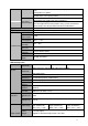
Compatible SD Card List Please refer to the following sheet for compatible SD card brand. Brand Standard Capacity Transcend SDHC6 16GB Kingston SDHC4 4GB Kingston SD 2GB Kingston SD 1GB Sandisk SDHC2 8GB Sandisk SD 1GB Card type SD SD SD SD Micro-SD Micro-SD Compatible Portable HDD List Please refer to the following sheet for compatible portable HDD brand. Brand Model Capacity YDStar YDstar HDD box 40G Netac Netac 80G Iomega RPHD-CG" Iomega 250GB RNAJ50U287 WD Elements WCAVY1205901 1.
Manufacturer Series Model Capacity Port Mode Seagate Barracuda.10 ST3750640AS 750G SATA Seagate Barracuda.10 ST3500630AS 500G SATA Seagate Barracuda.10 ST3400620AS 400G SATA Seagate Barracuda.10 ST3320620AS 320G SATA Seagate Barracuda.10 ST3250620AS 250G SATA Seagate Barracuda.10 ST3250820AS 250G SATA Seagate Barracuda.10 ST3160815AS 160G SATA Seagate Barracuda.10 ST380815AS 80G SATA Seagate Barracuda.9 ST3160811AS2 160G SATA Seagate Barracuda.
Western Digital CE series WD10EVCS 1T SATA Western Digital Cariar SE WD3200JD 320G SATA Western Digital Cariar SE WD3000JD 300G SATA Western Digital Cariar SE WD2500JS 250G SATA Western Digital Cariar SE WD2000JD 200G SATA Western Digital Cariar SE WD1600JD 160G SATA Western Digital Cariar SE WD1600JS 160G SATA Western Digital Cariar SE WD1200JS 120G SATA Western Digital Cariar SE WD800JD 80G SATA Western Digital Cariar WD1600AABS2 160G SATA Western Digital
APPENDIX C Compatible CD/DVD Device List NOTE: Please upgrade the NVS firmware to latest version to ensure the accuracy of the table below. And you can use the USB cable with the model recommended to set USB burner.
Appendix D Compatible Displayer List Please refer to the following sheet for the compatible device information.
Appendix E Compatible Switcher List Please refer to the following sheet form compatible switcher list. Brand Model D-LinK DES-1016D D-LinK DES-1008D Ruijie RG-S1926S H3C TP-LINK TP-LINK H3C-S1024 TL-SF1016 TL-SF1008+ Network Working Mode 10/100M self-adaptive 10/100M self-adaptive There are five network modes: 1. AUTO 2. HALF-10M 3. FULL-10M 4. HALF-100M 5.
Appendix F Compatible Wireless Mouse List Please refer to the following sheet for compatible SD card brand.
Appendix GEarthing 1. What is the surge? Surge is a short current or voltage change during a very short time. In the circuit, it lasts for microsecond. In a 220V circuit, the 5KV or 10KV voltage change during a very short time (about microseconds) can be called a surge. The surge comes from two ways: external surge and internal surge. The external surge: The external surge mainly comes from the thunder lightning. Or it comes from the voltage change during the on/off operation in the electric power cable.
work. The signal lightning arrester has many specifications, and widely used in many devices such as telephone, network, analog communication, digital communication, cable TV and satellite antenna. For all the input port, especially those from the outdoor, you need to install the signal lightning arrester. Antenna feed cable lightning arrester: It is suitable for antenna system of the transmitter or the device system to receive the wireless signal. It uses the serial connection too.
Mixed ground: The mix ground consists of the feature of the one-point ground and multiple-point ground. For example, the power in the system needs to use the one-point ground mode while the radio frequency signal requires the multiple-point ground. So, you can use the following figure to earth. For the direct current (DC), the capacitance is open circuit and the circuit is one-point ground. For the radio frequency signal, the capacitance is conducive and the circuit adopts multiple-point ground.
The monitor system usually can adopt the one-point ground. Please connect the ground end of 3-pin socket in the monitor system to the ground port of the system (protection ground cable) 4. The shortcut way to check the electric system using the digital multimeter For 220V AC socket, from the top to the bottom, E (ground cable), N (neutral cable), L(live cable). Please refer to the following figure.
For L (live cable) Turn the digital multimeter to 750V AC, use your one hand to hold the metal end, and then the other hand insert the pen to the L port of the socket. See the following figure. If the multimeter shows 120, then you can see current live cable connection is standard. If the value is less than 60, then you can see current live cable connection is not proper or it is not the live cable at all.
Appendix H Toxic or Hazardous Materials or Elements Toxic or Hazardous Materials or Elements Component Name Pb Hg Cd Cr VI PBB PBDE Sheet Metal(Case) Plastic Parts(Panel) ○ ○ ○ ○ ○ ○ ○ ○ ○ ○ ○ ○ Circuit Board ○ ○ ○ ○ ○ ○ Fastener Wire and Cable/AC Adapter Packing Material Accessories ○ ○ ○ ○ ○ ○ ○ ○ ○ ○ ○ ○ ○ ○ ○ ○ ○ ○ ○ ○ ○ ○ ○ ○ Note O: Indicates that the concentration of the hazardous substance in all homogeneous materials in the parts is below the rele