HD (IR) Vandal Proof Network Dome Camera User’s Manual Version 1.1.
Welcome Thank you for purchasing our network camera! This user’s manual is designed to be a reference tool for your system.
Important Safeguards and Warnings 1.Electrical safety All installation and operation here should conform to your local electrical safety codes. The power shall conform to the requirement in the SELV (Safety Extra Low Voltage) and the Limited power source is rated 12V DC or 24V AC in the IEC60950-1.
Do not touch the CCD (CMOS) optic component. You can use the blower to clean the dust on the lens surface. Always use the dry soft cloth to clean the device. If there is too much dust, please use the water to dilute the mild detergent first and then use it to clean the device. Finally use the dry cloth to clean the device. Please put the dustproof cap to protect the CCD (CMOS) component when you do not use the camera.
Table of Contents 1 General Introduction .................................................................................................................. 1 1.1 Overview ........................................................................................................................ 1 1.2 Features ......................................................................................................................... 1 1.3 Specifications ........................................................
5.1 Network Connection................................................................................................... 28 5.2 Login and Main Interface ........................................................................................... 28 FAQ ............................................................................................................................................ 31 Appendix Toxic or Hazardous Materials or Elements .........................................................
1 General Introduction 1.1 Overview This series network camera integrates the traditional camera and network video technology. It adopts audio and video data collection, transmission together. It can connect to the network directly without any auxiliary device. This series network camera uses standard H.264 video compression technology and G.711a audio compression technology, which maximally guarantee the audio and video quality.
time; it may result in device damage! Assistant Function Log function Support PAL/NTSC Support system resource information and running status real-time display. Day/Night mode auto switch (electromagnetic ICR switch). Built-in IR light. Support IR night vision (For HDBW Series only). Backlight compensation: screen auto split to realize backlight compensation to adjust the bright. Support electronic shutter and gain setup. Support video watermark function to avoid vicious video modification.
Video Bit Rate Video Flip Audio Snapshot Privacy Mask Video Setup Video Information Lens Lens Interface Audio Input Audio Output Bidirectional Talk Input Audio Bit Rate Audio Compression Standard Video Motion Detect Video Loss Alarm Input H.264: 56Kbps-8192Kbps. It is adjustable MJPEG: 128Kbps-0480Kbps. It is adjustable and bit rate is adjustable. Support customized setup. Support mirror. Support flip function. Max 1f/s snapshot. File extension name is JPEG.
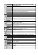
1.3.2 Factory Default Setup Please refer to the following sheet for factory default setup information. Function Setup Type Conditions Camera Setup Brightness Default setup ICIP D1300VIR Series 50 Contrast 50 Hue 50 Saturation 50 Gain mode Auto Gain limit 80 Exposure mode Auto Auto iris Enable Scene mode Auto Day/night mode Auto BLC Off Flip Disable Item Video Main stream Video stream bit Extra stream Bit stream type General Encode mode H.
Function Setup Type Default setup ICIP D1300VIR Series Item rate Snapshot Overlay Path Audio Main stream Sub(Extra) stream TCP/IP Network setup Connection Bit rate 640 I frame interval 50 Snap type General snap Image size 720P (1280*720) Quality Better Interval 7s Privacy mask Enable Channel title Enable Time title Enable Snapshot path C:\PictureDownload Record path C:\RecordDownload Enable Enable Encode mode G.711A Enable Disable Encode mode G.
Function Setup Type RTSP port Default setup ICIP D1300VIR Series 554 Enable Disable User name N/A Password N/A Server type Disable ,CN99 DDNS Server IP none Port 80 Domain name none User name none Password N/A Update period 5m Trusted sites Disable SMTP server none Port 25 Anonymity Disable User name anonymity Password N/A Sender none Authenticatio n (Encrypt mode) N/A Title (Subject) IPC Message Main Receiver N/A Interval 0s Health email Disable ,interval=60m
Function Setup Type Default setup ICIP D1300VIR Series Item Multicast address 239.255.42.42 Port 36666 Enable Disable SN 1 Server IP 0.0.0.
Function Setup Type Anti-dither Default setup ICIP D1300VIR Series 5s Sensor type NO Record channel Enable Record delay 10s Relay (Alarm) output Enable Relay (Alarm) delay 10s Send email Disable Activation N/A Address 0 Snapshot Disable Item Relay output No SD card Capacity warning Abnormity (Alarm) 1 SD card error Enable Disable Relay (Alarm) output Enable Relay output delay 10s Send email Disable Enable Disable Capacity limit (Space threshold) 10% Relay (Alarm) outpu
Function Setup Type Default setup ICIP D1300VIR Series Item (Alarm) output IP conflict FT P Destination(Storag e) Network storage Storage management Conditions control) (Record Local setup General setup Date and time System management Relay output delay 10s Enable Disable Record Enable Record delay 10s Relay (Alarm) output Enable Relay output delay 10s FTP enable Disable Server IP N/A Port 21 User name anonymity Password N/A Remote storage path share Emergency storage to
Function Setup Type Item DTS type Auto maintenance Default setup ICIP D1300VIR Series Week Start time 00:00:00 of the first Sunday of the month End time 00:00:00 of the second Monday of the month Synchronize with NTP Disable NTP server clock.isc.
2 Structure 2.1 Dimensions You can refer to the following figures for dimension information. The Unit is mm. See Figure 2-1 and Figure 2-2. Figure 2-1 Figure 2-2 2.2 Port Description For the non-IR series product, the interface is shown as in Figure 2-3 and Figure 2-4.
Figure 2-3 Figure 2-4 For the IR motorized zoom lens series product, the interface is shown as in Figure 2-5 and Figure 2-6.
Figure 2-5 Figure 2-6 For the IR manual zoom lens series product, the interface is shown as in Figure 2-7 and Figure 2-8.
Figure 2-7 Figure 2-8 Please refer to the following sheet for external connection port definition information. SN Port 1 POWER 2 POWER 3 Cable of Port Name AC 24V port DC 12V port exit the / power power Connector Function Description / Connect to AC 24V power. / Connect to DC 24V power. / Cable exit.
external connected cable 4 LAN RJ45 port network 5 I/O I/O port 6 RESET Reset button / 7 AUTO FOCUS 5-direction button / 8 Status indicator light / Ethernet port / / Network cable port. It includes alarm input/output, audio and analog output. Reset button. It is to restore factory default setup. Adjust lens angle of view and definition. Note: Only some models have this function. Display device running status. Connect to fan to reduce device internal problem.
Please connect the speaker or the MIC to the audio input port of the device. Then connect the earphone to the audio output port of the PC. Login the Web and then click the Talk button to enable the bidirectional talk function. You can see the button becomes orange after you enabled the bidirectional talk function. Click Talk button again to stop the bidirectional talk function.
Figure 2-9 Please refer to the following figure for alarm input information. See Figure 2-10. Alarm input: When the input signal is idle or grounded, the device can collect the different statuses of the alarm input port. When the input signal is connected to the 5V or is idle, the device collects the logic “1”. When the input signal is grounded, the device collects the logic “0”. Figure 2-10 Please refer to the following figure for alarm output information. See Figure 2-11.
3 Installation Important Before you complete the installation and setup, do not remove the electrostatic attraction film on the transparent enclosure. Otherwise it may result in injury. After remove electrostatic attraction film, do not touch dome enclosure in case it may leave stain. Before the installation, please make sure the installation surface can sustain at least 3X weight of the bracket and the camera. 3.
Figure 3-2 Step 1 Take the installation position map from the accessories bag and then paste it on the installation ceiling or the wall according to the monitor area. Please dig three bottom holes of the plastic expansion bolts according to the map. Take three expansion bolts from the accessories bag and then insert them to the holes you just dug and then fix firmly.
Figure 3-4 Step 5 Please refer to the Step 3 to put the driver module back to the metal hooks of the chassis. Then use the inner hex wrench to secure the two inner hex screws to the chassis. Then connect the network cable and the power terminal. Step 6 Adjust the lens to the proper angle according to your monitor requirements. a) For the IR series product, you can skip current step and go the step b) directly.
Lock Screw A Adjust lend pan rotation angle. Figure 3-6 c). Lens tilt rotation angle. Please refer to Figure 3-7 to unfasten the lock screw B and lock screw C and adjust the tilt monitor angle to the proper position. Then fix the lock screw B and lock screw C. The tilt angle ranges from -23°~+73°. d). Image pan rotation angle setup. Please refer to Figure 3-7 to turn lock screw D to adjust the video pan angle. Then fix the lock screw B and C. The video pan angle ranges from 0°~+350°.
Please note Figure 3-6 and Figure 3-7 is based on the IR motorized zoom camera. For the IR manual zoom camera and non-IR series product, the lock screw position and the lens angle adjustment are the same. Step 7 Line up the dome camera protection enclosure to the cable exit on the side panel. Put the enclosure back and then use the inner hex wrench to secure the 3 inner hex screws firmly. Now the installation is complete.
Dig through here Figure 3-9 For some special user, he may need the metal protection tube to protect when he pulls through the cable from the side cable. There is PG11screw thread port when you pull through the cable from the side panel. Please remove the plastic decoration plug from the side panel of the chassis and pull through the cable to the tunnel of the PG11 screw thread. Now secure the tunnel in the PG11 screw threaded hole of the device. 3.2.4 Cable Connection The device reserves two cable exits.
Step 2 Before you go to the Step 4 in the chapter 3.2.1 installation steps, please pull through cable with the waterproof airproof plug to the device chassis via the installation hole at the bottom of the chassis and then connect the cable pins. Step 3 Refer to Step 4 and Step 5 in the chapter 3.2.1 installation steps to install and connect the cable pin to the device and then follow the proper steps to go on the installation.
4 Quick Configuration Tool 4.1 Overview Quick configuration tool can search current IP address, modify IP address. At the same time, you can use it to upgrade the device. Please note the tool only applies to the IP addresses in the same segment. 4.2 Operation Double click the “ConfigTools.exe”icon, you can see an interface is shown as in Figure 4-1. In the device list interface, you can view device IP address, port number, subnet mask, default gateway, MAC address and etc.
Figure 4-2 Select the “Open Device Web” item; you can go to the corresponding web login interface. See Figure 4-3. Figure 4-3 If you want to modify the device IP address without logging in the device web interface, you can go to the configuration tool main interface to set. In the configuration tool search interface (Figure 4-1), please select a device IP address and then double click it to open the login interface.
Figure 4-4 After you logged in, the configuration tool main interface is shown as below. See Figure 4-5. Figure 4-5 For detailed information and operation instruction of the quick configuration tool, please refer to the Quick Configuration Tool User’s Manual included in the resources CD.
5 Web Operation These series network camera products support the Web access and management via PC. Web includes several modules: Monitor channel preview, system configuration, alarm and etc. 5.1 Network Connection Please follow the steps listed below for network connection. Make sure the network camera has connected to the network properly. Please set the IP address, subnet mask and gateway of the PC and the network camera respectively. Network camera default IP address is 192.168.1.108.
Figure 5-2 If it is your first time to login in, system pops up warning information to ask you whether install control webrec.cab or not after you logged in for one minute. Please click OK button, system can automatically install the control. When system is upgrading, it can overwrite the previous Web too. If you can’t download the ActiveX file, please check whether you have installed the plug-in to disable the control download. Or you can lower the IE security level. See Figure 5-3.
Figure 5-4 Please refer to the Web Operation Manual included in the resource CD for detailed operation instruction.
6 FAQ Bug I can not boot up the device. Please click RESET button for at least five seconds to restore factory default setup. Micro SD write times Do not set the Micro SD card as the storage media to storage the schedule record file. It may damage the Micro SD card duration. card I can not use the disk as the storage media. When disk information is shown as hibernation or capacity is 0, please format it first (Via Web). I can not upgrade the device via network.
Appendix Toxic or Hazardous Materials or Elements Toxic or Hazardous Materials or Elements Component Name Pb Hg Cd Cr VI PBB PBDE Circuit Board Component ○ ○ ○ ○ ○ ○ Device Case ○ ○ ○ ○ ○ ○ Wire and Cable ○ ○ ○ ○ ○ ○ Packing Components Accessories ○ ○ ○ ○ ○ ○ ○ ○ ○ ○ ○ ○ O: Indicates that the concentration of the hazardous substance in all homogeneous materials in the parts is below the relevant threshold of the SJ/T11363-2006 standard.