
User guide
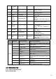


20
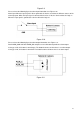
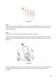
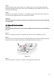
Figure 3-4
Step 5
Please refer to the Step 3 to put the driver module back to the metal hooks of the chassis. Then use the
inner hex wrench to secure the two inner hex screws to the chassis. Then connect the network cable
and the power terminal.
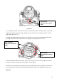
Step 6
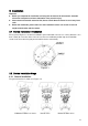
Adjust the lens to the proper angle according to your monitor requirements.
a) For the IR series product, you can skip current step and go the step b) directly. For the non-IR series
product, push the port slightly to remove the decoration enclosure from the black plastic enclosure. See
Figure 3-5.
Figure 3-5
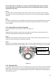
b) Lens pan rotation angle setup. Please refer to Figure 3-6 to unfasten the lock screw A and adjust the
pan monitor angle to the proper position. Then fix the lock screw A. The pan angle ranges from
0°~+350°.