SDI Quick Installation High Definition Speed Dome User’s Manual Version 1.2.
Table of Contents 1 FEATURES AND FUNCTIONS ..........................................................................................1 1.1 General Introduction...................................................................................................................................................1 1.2 Features .......................................................................................................................................................................1 1.2.
MENU .................................................................................................................................7 3.1 Screen Menu Index ..................................................................................................................................................7 3.2 Self-diagnosis System Information ..........................................................................................................................8 3.3 Main Menu .....................
Welcome Thank you for purchasing our product! This user’s manual is designed to be a reference tool for the operation of your system. Here you can find information about this speed dome features and functions, as well as a detailed menu tree.
Important Safeguards and Warnings 1.Electrical safety z z z z All installation and operation here should conform to your local electrical safety codes. The power shall conform to the requirement in the SELV (Safety Extra Low Voltage) and the Limited power source is rated 24V AC in the IEC60950-1. We assume no liability or responsibility for all the fires or electrical shock caused by improper handling or installation.
Always use all the accessories recommended by manufacturer. Before installation, please open the package and check that all the components are included in the package: Contact you local retailer ASAP if something is missing in your package.
1 Features and Functions 1.1 General Introduction The high definition SDI dome camera integrates the functions of remote surveillance and integrated highspeed smart dome, which makes it convenient to install and easy to use. This product enjoys a megapixel resolution, which meets the customers' needs for surveillance at HD level. This product is also qualified with intelligent identification ability, privacy masking settings, alarm activation, WDR and some other functions.
Privacy masking is a user-defined, four-sided area that can not be viewed by you. The masking area will move with pan and tilt functions and automatically adjust in size as the lens zooms. 1.2.10 Action on Alarm This series quick-installed high definition speed dome has 7 alarm inputs (normal open or normal close) and 2 alarm outputs (normal open). Alarms can be individually programmed to initiated pattern, or go to an associated preset, scanning, touring when received.
All digital design. All data are in the connection board. No data loss when power off occurs. z z Built-in Decode z z z z z z z Built-in PTZ Built-in zoom lens, high sensitive, high resolution integrated digital process color camera. z Fine stepper driver, stable performance, react quickly, precisely positioning. Integrated design, tight structure. Elegant mechanical driver device. Support 360 degrees continuous rotation, no monitor blind spot. z 0.1°/s rotation speed while maintain stable image.
Power Camera Driver Consumption Decoder Engine Preset Auto Tour Auto Pattern Auto Scan Privacy Mask Alarm Input/Output Information Lens Auto Rotation Auto Pan Manual Pan Motion Speed Preset Maximum Speed Manual Tilt Motion Manual Tilt Scan Section PTZ Scan Accuracy Signal Format S/N Ratio Humidity Environment AC 24V/3A(±10%) 15W/40w(Outdoor heater is on) Built-in Stepper motor 255(In PELCOD, PELCOP protocol). 80 (In industrial protocol) Please note the value may vary due to different protocols.
2 Protocol, Baud Rate, Address Setup Before you operate, you need to set protocol, baud rate and address. Otherwise you can not control the product! 2.1 Protocol and Baud Rate Setup Please configure the following settings before begin controlling dome: z Baud rate z Address Note: Please reboot the speed dome to get all the setups activated! Open the lower dome, the interface is shown as below. See Figure 2-1. The two dial switches of the quick installation speed dome are SW1 and SW2.
OFF OFF 9600bps ON OFF 4800bps OFF ON 2400bps ON ON 1200bps Please refer to the parity setup sheet for detailed information. 7 8 Parity OFF OFF NONE ON OFF EVEN OFF ON ODD ON ON NONE 2.2 Set address dial switch SW1 is to set the address. See Figure 2-2. Figure 2-2 The encode mode adopts binary system. 1 to 8 is valid bit. The highest address bit is 255. You can refer to the following sheet for more information.
3 Menu 3.1 Screen Menu Index Note: ERR means current setup is invalid. Please restore factory default setup. Slight difference may be found in the parameter interface due to different product series.
Note: z ERR means current setup is invalid. z Please make sure all the cable connections are right. 3.2 Self-diagnosis System Information ADDR BAUD RATE PARITY SOFTWARE :001-H :9600 :None :V1.00.0.R INITIALIZATION COMPLETED After installation, please connect speed dome to power. The system goes on a self-diagnosis, and then it pops up the above interface to show the system information. If there is anything wrong during the self-diagnosis, system pops up error code.
z and etc. EXIT: Log out the system menu. 3.4 Menu Operation In the speed dome main menu, you can use the left/right button on the keyboard or in the speed dome terminal menu to configure the system menu. Before setup, please move the cursor to the current item you want to configure. z In main menu, please click confirm button to go to the sub menu or use left/right key to configure setup. z Use up/down button to select back option and then click confirm button to go back to the previous menu.
Move the cursor to INITIAL INFORMATION and then click confirm button, you can see the above interface. Here you can view dome basic information. 3.4.1.2 Address Information ADDR TYPE ADDR-HARD ADDR-SOFT BACK EXIT : HARD : 001 : 001 Move the cursor to SITE INFORMATION and then click confirm button. z ADDR TYPE: There are two options: soft and hard. Please use the left/right button on the keyboard or in the speed dome terminal menu to set.
z z z z z z z TIME DISP: Display dome system time or not. Please use the left/right button on the keyboard or in the speed dome terminal menu to set. POSITION: Display the angel between the benchmark and then current location. Please use the left/right button on the keyboard or in the speed dome terminal menu to set. ZOOM DISP: Display speed dome zoom speed or not. Please use the left/right button on the keyboard or in the speed dome terminal menu to set.
z z z NEXT PAGE: It includes the following options: APERTURE RESTRAIN. DIGITAL ZOOM, PICTURE FLIP, FREEZE FUNCTION, AF SENSITIVITY, CAMERA FACTORY DEFAULT SETUP, CAMERA RESTART. Please use the left/right button on the keyboard or in the speed dome terminal menu to set. BACK: Go back to previous menu. EXIT: Log out system menu. 3.4.3.1 White Balance Setup WB MODE : AUTO R GAIN : 001 B GAIN : 001 BACK EXIT Move the cursor to WHITE BALANCE MODE and then click confirm button, you can go to the submenu.
z z z z z z EXPOSURE COM: Please use the left/right button on the keyboard or in the speed dome terminal menu to set. SLOW AE: In the strong light environment, you can lower the camera exposure speed to capture the image and enhance the definition. Please use the left/right button on the keyboard or in the speed dome terminal menu to set. SLOW SHUTTER: In lower illumination environment, you can lower the cameras auto exposure time to capture the image and enhance the definition.
z z z z THRESHOLD: The speed dome can switch the day/night mode when it reached the threshold you set here. SAVE: This button is for DAY TIME and NIGHT TIME setup. After you set the day time (or night time), you need to move the cursor here and then click confirm button to save current time setup. For other setups, you do not need to use this button. BACK: Go back to previous menu. EXIT: Log out system menu. 3.4.3.
z z BACK: Go back to previous menu. EXIT: Log out system menu. 3.4.3.6 Next Page Move the cursor to NEXT PAGE and then click confirm button, you can go to the submenu. DIGITAL ZOOM : Off DIGITAL ZOOM LIMIT :X3 PICTURE FLIP : OFF FREEZE FUNC : OFF STABALIZATION: : NORMAL OUTPUT MODE :1020P/25 CAMERA FACTORY DEFAULT CAMERA RESTATRT BACK EXIT z z z z z z z z z z DIGITAL ZOOM: You can use the left/right button to enable/disable the digital zoom function.
z z z z z z z z AUTO SCAN: Move the cursor to SCAN and then click confirm button to go to the third submenu. AUTO CRUISE: Move the cursor to AUTO CRUISE and then click confirm button to go to the third submenu. AUTO PATTERN: Move the cursor to PATTERN and then click confirm button to go to the third submenu. IDLE MOTION: Move the cursor to IDLE MOTION and then click confirm button to go to the third submenu. TIME TASK: Move the cursor to TIME TASK and then click confirm button to go to the third submenu.
z Set preset: Set preset 26 or 92 to set scan left limit. Set preset 27 or 93 to set scan right limit. Set preset 22 or 79 to begin record. Set preset 23 or 80 to stop record. 3.4.4.2 Pan PAN SPEED RUN STOP BACK EXIT :160 Move the cursor to PAN button and then click confirm button to go to setup interface. z PAN SPEED: Set dome rotation speed. Please use the left/right button on the keyboard or in the speed dome terminal menu to set. z RUN: Move the cursor to call item and then click confirm button.
Move the cursor to highlight CRUISE item and then click confirm button to go to set interface. z z CRUISE NO :Here is to ser tour number. The value ranges from 1 to 8. Please use the left/right button on the keyboard or in the speed dome terminal menu to set. CRUISE SETTING: Move the cursor to cruise setting item and then click confirm button. You can see the following interface. Here you can add or remove the preset, and set the corresponding dwell time and call speed. One cruise can max have 32 presets.
Move the cursor to PATTERN and click confirm button. z PATTERN NO: Here is to set pattern number. The value ranges from 1 to 5. Please click left/right key z to configure. PROGRAM START: Here is to memorize pattern starting point. An icon OK pops up in screen to prompt you system begins memory pattern. z PROGRAM STOP:Here is to set pattern stop point. After all the movement, move the cursor to PROGRAM STOP and then click confirm button. Now you have set one pattern.
TASK NO :1 TIME TASK :OFF TASK SETTING TASK INFORMATION DELETE TASK BACK EXIT • • TASK NO: Here you can set task number. Please use the left’/right button to set. TIME TASK: The schedule task allows the speed dome to implement corresponding setup during the specified time. There are two options: on/off. Please use the left/right button on the keyboard or in the speed dome terminal menu to set. • TASK SETTING: Here you can set task time, operation, operation SN and etc.
Move the cursor to the TASK INFORMATION and then click the confirm button to go to the following interface. Here you can see the corresponding task information. Click the confirm button again, you can exit current interface. NO TIME ACTION 1 ALL 00:00-00:00 SC001 OFF 2 ALL 00:00-00:00 SC001 OFF 3 ALL 00:00-00:00 SC001 OFF 4 ALL 00:00-00:00 SC001 OFF 5 ALL 00:00-00:00 SC001 OFF 6 ALL 00:00-00:00 SC001 OFF 7 ALL 00:00-00:00 SC001 OFF 3.4.4.
Move the cursor to PRIVACY MASK and click confirm button, system goes to privacy mask setup interface. PRIVACY NO :001 ACTIVATE : OFF RESIZE :↑ DELETE SAVE BACK EXIT Note: z For security reasons, please set privacy zone a little bit larger than the privacy object size. z Each time, after modifications you need to move the cursor to SAVE button and then click confirm button to get all setup activated. Otherwise, privacy zone may not move correspondingly with the object.
• POWER UP: It is to set the PTZ operation when the speed dome boots up. The option includes: NONE/AUTO/SCAN/PRESET/PATTERN/TOUR and etc. Please use the left/right button to set. • PARAMTER: Here you can set the serial number of the corresponding operation such as the scan, preset, pattern, tour. Please use the left/right button to set. • • BACK: Go back to the previous menu. EXIT: Log out the system menu.
4 Cable Connection Multiple-function combination cable consists of video terminal, RS485 terminal and relay in/out terminal. Please refer to the following instruction labels for further reference. RS485, video interface, power port is shown as below: Name Function A 485-A. It is to control dome built-in PTZ. B 485-B. It is to control dome built-in PTZ. GND Ground. GND AC24V Ground. Video output port. You can connect this port if you want to use the analog video output. 24V power port.
4.1.1.1 BUS connection Please refer to Figure 4-1 and Figure 4-2 for BUS cable connection. Figure 4-1 Figure 4-2 Note: Please use shielded twisted pair. The shielded layer shall connect to GND firmly; otherwise it may affect communication or video work. 4.1.1.2 Star Connection Please refer to Figure 4-3 for start connection information. Figure 4-3 4.1.2 Alarm Connection Please refer to Figure 4-4 for alarm connection information.
Figure 4-4 4.1.3 Keyboard Connection This series dome supports keyboard operation. You can use keyboard to control the dome and PTZ. The display and control can work simultaneously. One keyboard can control maximum 255 speed domes. Please refer to Figure 4-5. Figure 4-5 Speed dome protocol is open and supports multiple popular system platforms in today’s market. Please contact us freely if some matrix systems do not support dome camera communication protocol.
Figure 4-6 27
5 FAQ 5.1 Daily Maintenance Please clean dome cover regularly to get vivid image. Handle the cover with care. Use water to wash. Don’t use cloth to clean. Use mild detergent to clean if there is too much dust. Note: The sweat from your hand may erode plating surface, your nail may scrape dome cover result in blur image. 5.2 Problems and Solutions SYMPTOM No self-diagnosis, no video signal when I connect dome to power. No self diagnosis. There is a noise Video signal loss occurs in high speed rotation.
6 Appendix Ⅰ Thunder Proof and Surge Protection This series speed dome adopts TVS lighting protection technology. It can effectively prevent damages from various pulse signals below 4000V, such as sudden lighting and surge. While maintaining your local electrical safety code, you still need to take necessary precaution measures when installing the speed dome in the outdoor environment.
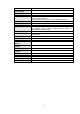
7 Appendix 2 Toxic or Hazardous Materials or Elements Toxic or Hazardous Materials or Elements Component Name Pb Hg Cd Cr VI PBB PBDE Sheet Metal ○ ○ ○ ○ ○ ○ Plastic Parts ○ ○ ○ ○ ○ ○ PCB ○ ○ ○ ○ ○ ○ Housing ○ ○ ○ ○ ○ ○ ○ ○ ○ ○ ○ ○ Bearing ○ ○ ○ ○ ○ Connection Cable ○ ○ ○ ○ ○ ○ Motor (If possible) ○ ○ ○ ○ ○ ○ Power (If possible) ○ ○ ○ ○ ○ ○ Bracket (If possible) ○ ○ ○ ○ ○ ○ Accessories ○ ○ ○ ○ ○ ○ Camera Driver ○ Note O: Indi
Note • This manual is for reference only. Slight difference may be found in the user interface. • All the designs and software here are subject to change without prior written notice. • If there is any uncertainty or controversy, please refer to the final explanation of us. • Please visit our website or contact your local service engineer for more information.