HD IR Waterproof Fixed Network Camera User’s Manual Version 1.0.
Welcome Thank you for purchasing our network camera! This user’s manual is designed to be a reference tool for your system.
Important Safeguards and Warnings 1.Electrical safety All installation and operation here should conform to your local electrical safety codes. The power shall conform to the requirement in the SELV (Safety Extra Low Voltage) and the Limited power source is rated 12V DC in the IEC60950-1. This series product supports PoE too.
Do not touch the CCD (CMOS) optic component. You can use the blower to clean the dust on the lens surface. Always use the dry soft cloth to clean the device. If there is too much dust, please use the water to dilute the mild detergent first and then use it to clean the device. Finally use the dry cloth to clean the device. Please put the dustproof cap to protect the CCD (CMOS) component when you do not use the camera. 7. Accessories Be sure to use all the accessories recommended by manufacturer.
Table of Contents 1 General Introduction .................................................................................................................. 1 1.1 Overview ........................................................................................................................ 1 1.2 Features ......................................................................................................................... 1 1.3 Specifications ........................................................
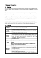
1 General Introduction 1.1 Overview This series network camera integrates the traditional camera and network video technology. It adopts video data collection, transmission together. It can connect to the network directly without any auxiliary device. This series network camera uses standard H.264 video compression technology, which maximally guarantees the video quality. It supports the IR night vision function.
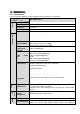
1.3 Specifications 1.3.1 Performance System Please refer to the following sheet for network camera performance specification. Model ICIP B2000S Series Parameter Main Processor TI Davinci high performance DSP OS Embedded LINUX System Support real-time network, local record, and remote operation at the Resources same time. User Interface Remote operation interface such as WEB, DSS, PSS System Status Bit stream statistics, log, and software version.
Remote Operation Restore Default Setup IR light General Parameter Power Power Consumption Working Temperature Working Humidify Dimensions(mm) Weight Installation SNMP. Monitor, system setup, file download, log information, maintenance , upgrade and etc Reset button IR light 20-30M. DC12V power and PoE. 6W MAX -10℃~+60℃ 10%~90% 70*66*160 0.5Kg(Excluding box) Bracket installation 1.3.2 Factory Default Setup Please refer to the following sheet for factory default setup information.
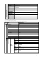
Setup Default Setup ICIP B2000S Series Item Sub Stream Snapshot Video Overlay Path Network TCP/IP Watermark character DigitalCCTV Enable Enable Bit stream type General Encode mode H.
Setup Default Setup ICIP B2000S Series Item DNS Connection PPPoE DDNS IP Filter SMTP(Email) Enable ARP/Ping set device IP address service Enable Max Connection 10 TCP Port 37777 UDP Port 37778 HTTP Port 80 RTSP Port 554 HTTPs enable Disable HTTPs Port 443 Enable Disable Username none Password N/A Server Type Disable,CN99 DDNS Server IP none Server Port 80 Domain Name none User none Password **** Update Period 10 minutes Trusted sites Disable SMTP Server none P
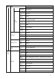
Setup Default Setup ICIP B2000S Series Item UPnP SNMP Bonjour Multicast QoS Video detect Event Motion Detect Video Masking Disconnectio Title (Subject) IPC Message Attachment N/A Mail Receiver 0 seconds Email Test Disable,interval=60 seconds Enable UPnP Disable SNMP Port 161 Read Community public Write Community private Trap Address N/A Trap Port 162 Enable Enable Server Name SN. It depends on the actual device. Multicast Address 239.255.42.
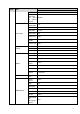
Setup Default Setup ICIP B2000S Series Enable Item n Record IP Conflict Record Delay 10 seconds Enable Disable Record Enable Relay Delay Storage Storage FTP Record Control General System Local Host Date time and Auto Maintenance out 10 seconds Enable FTP Disable Server IP N/A Port 21 Username anonymity Password N/A Remote path share Pack Duration 8 minutes Pre-record 5 seconds Disk Full Overwrite Record Mode Auto Record Stream Main stream Device No Device manufa
Setup Default Setup ICIP B2000S Series Item Auto Delete Old Files Disable 8
2 Structure 2.1 Multiple-function Combination Cable You can refer to the following figure for multiple-function combination cable information. See Figure 2-1. Figure 2-1 Please refer to the following sheet for detailed information. SN Port Name Function Connection Note 1. LAN Network port Ethernet port Connect to standard Ethernet cable. 2 DC12V Power port / Power input port. Input DC 12V. input 2.2 Framework and Dimension Please refer to the following two figures for dimension information.
Figure 2-2 Figure 2-3 10
3 Device Installation Important The installation wall shall min sustain 3X weight of the bracket and camera. Please follow the steps listed below to install the device. Please refer to Figure 3-1 and Figure 3-2 for reference. Step 1 Paste the installation map on the surface of the wall or the ceiling. Step 2 Dig the installation holes according to the installation map. Figure 3-1 Step 3 Open the accessories bag and then take the expansion bolt out. Insert the expansion bolt into the installation holes.
Figure 3-2 12
4 Quick Configuration Tool 4.1 Overview Quick configuration tool can search current IP address, modify IP address. At the same time, you can use it to upgrade the device. Please note the tool only applies to the IP addresses in the same segment. 4.2 Operation Double click the “ConfigTools.exe” icon; you can see an interface is shown as in Figure 4-1. In the device list interface, you can view device IP address, port number, subnet mask, default gateway, MAC address and etc.
Figure 4-2 Select the “Open Device Web” item; you can go to the corresponding web login interface. See Figure 4-3. Figure 4-3 If you want to modify the device IP address without logging in the device web interface, you can go to the configuration tool main interface to set. In the configuration tool search interface (Figure 4-1), please select a device IP address and then double click it to open the login interface.
Figure 4-4 After you logged in, the configuration tool main interface is shown as below. See Figure 4-5. Figure 4-5 For detailed information and operation instruction of the quick configuration tool, please refer to the Quick Configuration Tool User’s Manual included in the resources CD.
5 Web Operation This series network camera product supports the Web access and management via PC. Web includes several modules: monitor channel preview, system configuration, alarm and etc. 5.1 Network Connection Please follow the steps listed below for network connection. Make sure the network camera has connected to the network properly. Please set the IP address, subnet mask and gateway of the PC and the network camera respectively. Network camera default IP address is 192.168.1.108.
Figure 5-2 If it is your first time to login, system pops up warning information to ask you whether install control webrec.cab or not after you logged in for one minute. Please click OK button, system can automatically install the control. When system is upgrading, it can overwrite the previous Web too. If you can’t download the ActiveX file, please check whether you have installed the plug-in to disable the control download. Or you can lower the IE security level. See Figure 5-3.
Figure 5-4 Please refer to the Web Operation Manual included in the resource CD for detailed operation instruction.
6 FAQ Bug I can not boot up the device or operate properly. Please click RESET button for at least five seconds to restore factory default setup. The water leakage occurred. The unauthorized front or rear cap remove many result in water leakage. The glass front cap has sustained heavy push or strike. The waterproof plug of the rear cap becomes loosen. IR video is poor. Do not use the proper supplying power. The IR light can not turn on completely.
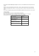
Appendix Toxic or Hazardous Materials or Elements Toxic or Hazardous Materials or Elements Component Name Pb Hg Cd Cr VI PBB PBDE Circuit Board Component ○ ○ ○ ○ ○ ○ Device Case ○ ○ ○ ○ ○ ○ Wire and Cable ○ ○ ○ ○ ○ ○ Packing Components Accessories ○ ○ ○ ○ ○ ○ ○ ○ ○ ○ ○ ○ O: Indicates that the concentration of the hazardous substance in all homogeneous materials in the parts is below the relevant threshold of the SJ/T11363-2006 standard.