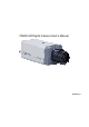
CMOS HD Digital Camera User's Manual Version 1.
Welcome Thank you for purchasing our camera! This user’s manual is designed to be a reference tool for your system.
Important Safeguards and Warnings 1.Electrical safety All installation and operation here should conform to your local electrical safety codes. The power shall conform to the requirement in the SELV (Safety Extra Low Voltage) and the Limited power source is rated 12V DC or 24V AC in the IEC60950-1. Before you replace the SD card, please unplug the power cable and then remove the shell We assume no liability or responsibility for all the fires or electrical shock caused by improper handling or installation.
CD ■ 1
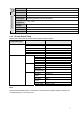
Table of Contents 1 General Introduction ..................................................................................................................6 1.1 Overview ........................................................................................................................6 1.2 Feature...........................................................................................................................6 1.3 Specifications ...........................................................
1 General Introduction 1.1 Overview This series camera conforms to the HD-SDI specifications. It supports high speed video signal, almost no delaying in the transmission. The HD-SDI interface adopts the coaxial cable and uses the BNC port as the cable standard. This series product has the Megapixel definition and supports the DC 12V/AC 24V power. 1.2 Feature Data Transmission z Adopt coaxial cable. Use the BNC port as the cable standard.
AUX Interfac e General Parameter Video Output Reset 1-channel SDI port RS485 Port Set video parameter Power Power Consumption Working Temperature Working Humidify Dimensions Weight Installation Support AC 24V/DC 12V power Hardware Reset button 7W MAX (5W MAX when the ICR switch) -10℃~+55℃ 10%~90% 70×63.2×149.5 650g Support various installation modes(Enclosure and bracket is optional) 1.3.2 Factory Default Setup Please refer to the following sheet for factory default setup information.
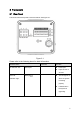
2 Framework 2.1 Rear Panel This series camera real panel is shown as below. See Figure 2-1. Figure 2-1 Please refer to the following sheet for detail information. Interface Name AC 24V/ DC 12V Connector Power port Function z Power port. z Input 12V DC or AC 24V STATUS Red light z Indication Light The red light is on when the system is working properly. z It flashes when the system is upgrading.
Green light z Hardware indication light. It is on after the hardware loaded successfully. Yellow light z Software indication light. It is on after the software loaded successfully. IN Reserved port I/O port N/A NO C G GND Alarm input ground end. A RS485 port RS485_A port. It is to control the 458 tool to set the video parameter. B RS485_B port. It is to control the 458 tool to set the video parameter. RX Reserved port N/A RESET button z TX G NA RESET Restore factory default setup.
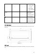
for at least 5 seconds, system can restore factory default setup. Yellow light flikers. HD-SDI Send out the SDI video stream conforming to the HDSDI specifications. GND Please make sure the device is securely earthed to prevent the thunderstorm strike. 2.2 Side Panel Please refer to the following interface for side panel dimension information. The unit is mm. See Figure 2-2. Figure 2-2 2.3 Lens Please refer to the following interface for lens dimension information. The unit is mm. See Figure 2-3.
Figure 2-3 11
3 Installation 3.1 Lens Installation 3.1.1 Auto Aperture Lens Please follow the steps listed below for auto aperture lens installation. The interface is shown as in Figure 3-1 and Figure 3-2. z Remove the CCD protection cap of the device, and then line up the lens to the proper installation position. Turn clockwise until the lens is fixed firmly. z Insert the lens cable socket to the auto lens connector in the side panel.
Figure 3-2 3.1.3 Remove Lens Please follow the steps listed below to remove lens. The interface is shown as in Figure 3-3. z Turn the lens counter clockwise and then remove it from the camera. z Unplug the auto lens cable socket from the auto lens connector. If you are using the manual aperture lens, please skip to the following step. z If there is no lens, please put the CCD protection cap back to protect the CCD. Figure 3-3 3.
Figure 3-4 14
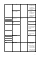
4 HDC Configuration Tool 4.1 Overview You can use HDC configuration tool to set the device parameter and upgrade the system. 4.2 Operation Double click the “485Configs.exe” icon; you can see an interface is shown as in Figure 4-1. In the device interface, you can view COM setup, parameter setup, OSD, upgrade information and etc. The parameter interface is shown as in Figure 4-1. Figure 4-1 The OSD interface is shown as in Figure 4-2. Figure 4-2 The upgrade interface is shown as in Figure 4-3.
Figure 4-3 You can refer to the following sheet for detailed information. Item Note COM Select the corresponding COM number. COM Setup Baud rate Default value is 115200 (Read-only) Parity None Data bit Default value is 8 (Read-only). Stop bit Default value is 1 (Read-only). Parameter Setup Current status Color Brightness Contrastness Hue Saturation BLC Exposure Shutter Display the corresponding COM status. Set the brightness value to adjust the video bright and dark level.
1/50s, 1/120s, … Customized zone: After you selected current mode, you can see there is a period setup interface. System can auto adjust in the period you specified. z Customized value: After you selected the mode, you can see the time period setup interface. You can input the shutter value in the current interface. It includes two modes: auto/manual. You can check the box to select the corresponding mode. z In the manual mode, your input value is the actual value.
Figure 4-4 18
Appendix Toxic or Hazardous Materials or Elements Component Name Toxic or Hazardous Materials or Elements Pb Hg Cd Cr VI PBB PBDE Circuit Board Component ○ ○ ○ ○ ○ ○ Device Construction Material ○ ○ ○ ○ ○ ○ Wire and Cable ○ ○ ○ ○ ○ ○ Power Adapter ○ ○ ○ ○ ○ ○ Packing Components ○ ○ ○ ○ ○ ○ Accessories ○ ○ ○ ○ ○ ○ O: Indicates that the concentration of the hazardous substance in all homogeneous materials in the parts is below the relevant threshold of the SJ/T