Keyboard Operating Manual Version 1.
Table of Contents Welcome...................................................................................................................................5 Important Safeguarding and Warnings ................................................................................6 1 Features and Specifications ...........................................................................................7 1.1 Features ...................................................................................................
4.3.4 Empty Control Point ..................................................................................18 4.4 Assistant Setup ....................................................................................................18 4.4.1 Backlight Setup..........................................................................................18 4.4.2 Alarm Setup................................................................................................18 4.4.3 Language..................................
6.2 Keyboard Setup ...................................................................................................27 6.3 Operation ..............................................................................................................27 6.3.1 6.3.2 6.3.3 6.3.4 6.3.5 6.3.6 7 Direction Setup ..........................................................................................28 Preset ..........................................................................................................
Welcome Thank you for purchasing our network keyboard! This operating manual is designed to be a reference tool for the operation of your keyboard. Here you can find information about this keyboard features and functions, as well as a detailed menu tree. Before operation please read the following safeguards and warnings carefully! Please keep this operating manual well for future reference! Tips You can refer to chapter 8 for COM cable connection information.
Important Safeguarding and Warnings All installation and operation should conform to your local electrical safety codes. We assume no liability or responsibility for all the fires or electrical shock caused by improper handling or installation All the examination and repair should be done by the qualified service engineers. We are not liable for any problems caused by unauthorized modifications or attempted repair.
1 Features and Specifications 1.1 Features This series keyboard has the following features z One keyboard can control multiple DVRs, or you can use multiple keyboards to control one DVR. z Support dome operation. z Support RS485 port and RS232 port.
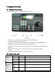
2 Keyboard Function 2.1 Keyboard Appearance The keyboard appearance is shown as below. See Figure 2-1. Figure 2-1 ① ② ③ ④ ⑤ Function key: There are three function keys: SETUP/ALARM/SHIFT LCD: Here is to display on-screen menu. Indication light: There are six indication lights. DVR/DOME/ALT/COM/ALARM/POWER. DVR function: Here are operation keys for you to control DVR. Public function: Here includes ten numeral keys, four direction keys, ESC/ENTER and ID/CAM.
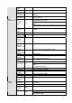
indication light Serial port COM indication lig Alarm ALARM indication lig Power POWER indication lig DVR function key Assistant function key Fn1 Light turns on when connected with serial port device Light turns on when connected with alarm devices Light turns on when keyboard connected with power an works properly. In single surveillance mode, click Fn1 to display PTZ a image color setup menu.
Confirm ENTER Direction ke ©up ª down § left ¨right Dome/ Matrix key function Assistant function key Previous pa PREV Dome MENU menu Next page NEXT Scan SCAN Tour AUTO-PAN Pattern PATTERN Set SET preset GOTO prese GOTO Remove REMOVE preset Iris TELE zoom in PTZ P/T Iris WIDE zoom out Focus NEAR zoom in Wiper WIPER Focus FAR zoom out Lens CLOSE zoom out Lens OPEN zoom in Light LIGHT Joystick AUX1----AUX6 Confirm current operation In single surveillance mode, click up/down to switch between various channe
Figure 2-2 ① RJ45 network port ② RS485 port ③ RS232 port ④ Power socket 2.4 Port Features RS232 can directly connect with DVR. The distance should be within 10m. One RS232 port could only connect with one DVR. You must use 485-> 232 converters to connect more DVRs. RS-485 transmission distance is 1200 m(9600bps),max 3000 m. In level-link mode, one RS-485 port can connect with as many as 16 keyboards. You can connect RJ45 with DVR and realize front device multiplex control via the network keyboard. 2.
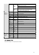
Net setting 3 Menu Tree Time setting Key board menu tree is shown as below.
3.1 Input Method Click SHIFT, you can switch between numeral/capitalized character/small character. z c: Numeral z A: Capitalized character z @ Small character. 3.2 Log In Plug in power socket, power indication light is on. You can see welcome information in LCD. Network keyboard 2006-12-20 14.00.00 Click Enter or SETUP, system pops up a dialogue box. Now you can input user name and password. The default user is admin, password is 888888.
4 Menu Operation Menu operation includes five items: z Local setup z CTL point z Advance z Assistant z System information 4.1 Local Setup Local setup includes the following items z Network setup z Time setup z Address setup 4.1.1 Network Setup (for network keyboard only) Network setup is for you to input the following information. z IP z Sub mask z Net gate z Port You can use left/right key to highlight corresponding item and then input numeral. IP ADD: 192.168.000.118 Sub Mask: 255.255.255.
z z Device type Connection type Network connection RS232 RS485 ID:*3 Dev name: DVR-1 Dev Type: DVR Connection type: RS232 4.2.1 ID Here is for you to input front device ID. Move the cursor to highlight ID and then use input numeral. If there is a * before the ID number (such as *3), it means that front device has control point setup. You can view device *3 corresponding type and name. 4.2.2 Device Name Here is for you to input device name.
z S-bit 232ADD: PRTCL: Baud: D-bit: O_E VFY: S-Bit: 4.2.4.3 RS485 When connection type is RS485, click ENTER key you can see an interface ask you to input the following information z 232ADD z PRTCL z Baud z D-bit z O_E VFY z S-bit 485ADD: PRTCL: Baud: 300 D-bit: 8 O_E VFY: None S-Bit: 1 Note: All the setup here should conform to you current connection type. If you input connection type is RS232, you front device should connect with keyboard via RS 232 port.
User: admin Password: c Confirm 4.3.2 User Management User management is for administrator only. Administrator can add, delete or modify user, set power for each user. Ordinary user can only modify its own password and operate all functions within power setting limit. Guest can not operate functions. He can only review DVR video or check version information. Add user Delete user Power setting 4.3.2.1 Add User Here is for you to add a new user. You can input new user name and password.
4.3.3 Set Local as Default Here is for you to restore factory default setup. Note: when you operate this function, please be careful! Set Local as Default? Yes: ENTER No: Esc 4.3.4 Empty Control Point Here is for you to delete all control point information. Click ENTER to clear all. Clear ALL CTL Point? Yes: ENTER No: Esc 4.4 Assistant Setup Assistant setup includes the following items: Back light: ON Alarm: ON Language: English 4.4.1 Backlight Setup You can open LCD backlight.
4.6 Control Point You can input either of the following information to search one device. System can automatically connect with that device and you can use keyboard to control it. For control keyboard: For network keyboard You can click ENTER to go to the above menu and then input corresponding property to search. E.g.: If you want to search a device of ID3. Input ID as 3 and then click ENTER to confirm. System pops up the following interface, ID 3 is a dome and its RS232 address is 3.
Control point includes the following items. z ID z Machine name z IP address z RS232 z RS485 ID Machine IP RS232 RS485 4.6.1 ID Use left/right to highlight ID and then click ENTER. Here is for you to input device ID. 4.6.2 Machine Name Use left/right to highlight Machine and then click ENTER. Here is for you to input machine name. 4.6.3 IP Address Use left/right to highlight IP address and then click ENTER. Here is for you to input device IP address. 4.6.
5 Keyboard Control DVR 5.1 Serial Port Connection 5.1.1 RS232 Serial Port Connection You can use one RS232 cable to connect DVR serial port and keyboard serial port together. See Figure 5-1. DVR address number ranges from 1 to 255,please refer to DVR manual for more information. RS232 cable DVR Figure 5-1 5.1.2 Via RS485 Connection You can use one RS232 port can only connect with one DVR. See Figure 5-2. You need to use RS 485 port once you want to control more than one DVRs.
A B … 485->232 converter 485->232 converter 485->232 converter …… Figure 5-3 One 485 bus can connect with thirty-two RS485->232 converters,one RS485->232 converter can connect with twelve DVRs. 5.1.3 Multi-keyboard link via RS485 You can use the following figure if you are connecting multiple keyboards via RS485 port. See Figure 5-4. Other 485 devices …… A B Figure 5-4 Multi-converter connection: The last converter on RS 485 port must be short circuited. (E.g.: open converter). See Figure 5-5.
5.2.1 RJ45 port connection 5.2.1.1 Direct connection Please refer to the Figure 5-6.for direct connection information. Crossover cable Figure 5-6 5.2.1.2 Connect via HUB Please refer to the following figure if you are connecting via the hub. See Figure 5-7. …… Straight-through cable Switch …… Figure 5-7 5.3 DVR and Keyboard Setup 5.3.1 DVR Setup Before operation, please make sure cable connection is proper. In DVR menu, from “Setting” to RS232. See Figure 5-8. The default setup is shown as below.
Figure 5-8 5.3.2 Keyboard Setup after Serial Port Connection In menu, go to control point setup. Here you need to input the following information. ID: *3 Dev name: DVR-1 Dev type: DVR Connection type: RS232 z ID: If there is a * before the ID number (such as *3), it means this front device has control point setup. You can view device *3 corresponding type and name. z Device name: Here is for you to give a name to the front device. z Device type There are several selections such as DVR/Dome/CMS/NVS.
DH2 is network keyboard/2nd generation control keyboard protocol, its corresponding DVR serial port protocol is network keyboard protocol. DH1 is the first generation keyboard protocol, its corresponding DVR serial port is control keyboard protocol or Dahua protocol. 5.3.3 Keyboard Setup after Network Connection ID, device name and device type setup please refer to 6.3.2. Use up/down to highlight connection type and then use left/right to select connection type. Click “ENTER” to go to setup.
Note: before click tour key, please make sure your current series DVR supports tour function. You can click tour key (3) to begin touring. F、 、 、 are corresponding to :One/four/nine/sixteen window display modes. You can click numeral key to go to corresponding channel. E.g. you can click numeral 1 to go to channel one. For channel number more than two-digit (such as numeral 11), you need work with CAM key. E.g., you want to go to channel 12 then you input CAM+12+CAM. 5.4.
6 Network Keyboard Control Dome 6.1 Cable Connection Please make sure keyboard AB line and dome AB line connection is right. Connect dome to power, and then connect dome video cable to the monitor. Before operating, please go to dome menu to go on setup. If dome address is 1, then keyboard RS 485 address is 1. 6.2 Keyboard Setup In keyboard menu, go to control point. Here you can input ID, device name. You can use left/right key to select device type.
Click MENU, the image is shown as below. The menu here should work with dome menu. 1. up 5.Previous menu 2. down 6.Next menu 3. Left 7.Confirm 4. Right 8.Exit 6.3.1 Direction Setup 6.3.1.1 Speed It is to control direction. The value ranges from one to eight. Please use the number buttons of the keyboard to input value (between 0~8) and press ENTER to confirm. (Operation here is only active with key-press. You can use joystick to control speed directly.
Note: for versatile scan and random scan, you need protocols to support. corresponding Value :1 Scan > start 6.3.4 Tour 6.3.4.1 Tour setup Scan setup Versatile scan Stop Use up/down keys to highlight add to tour. Input value in tour group. For example, here we want to add tour point 2 and 3 in tour group 1. Random scan Speed • Firstly, input 1 in tour group. • Secondly, input 2 to tour and then click ENTER. Now you have added tour point 2 to tour group 1.
Input value is the pattern path you want to set (Maximally support five paths). Click ENTER to confirm. • Move cursor to highlight start and then input pattern value. Now click ENTER to confirm. • Move cursor to highlight stop. Input pattern value and click ENTER to stop pattern. Dome will automatically memorize all the operations you have done. Pattern Value:1 Patter setup > Start Rotation Stop Pattern Value:1 6.3.5.
7 Keyboard Upgrade 7.1 Control Keyboard Upgrade Control keyboard does not support remote upgrade. Please ship your control keyboard back to our factory to upgrade. 7.2 Network Keyboard Upgrade Before upgrade, please make sure your network keyboard is well connected. You can use command “PING” to test network connection, the return value TTL should be less than 255. Please download upgrade file to your local PC. You can download upgrade file from our website or from our local service engineer.
Figure 7-3 32
8 Make COM Cable The keyboard standard accessories package includes the following items. z One DB9 z Seven DB9 z One six-pin crystal port z One 25-pin (DB25) z One 485 transmission box. (Including one power source.) 8.1 Make RS232 COM Cable Please refer to the following figure for RS232 port information. See Figure 8-1. RS232 serial port (DB9) RS232serial port (DB9) Figure 8-1 8.2 Make RS485 COM Cable You can refer to Figure 8-2 if you are connecting the keyboard with the switcher box.
Connect switch 25-pin box RS232 port with DVR RS232 port. (25-pin outlet supports maximum twelve RS232 ports. Switch is just for sending not for receiving. So you can use two cables: GND and TXD) Please refer to the following sheet if you are connecting 485 switch box to DVR See Figure 8-3. RS485switch box 25-pin port (DB25) RS232 port (DB9) Figure 8-3 Note: you can use standard RS232 port to connect keyboard with DVR. Note: z This manual is for reference only.