ATM Series-Standalone DVR User’s Manual 1
Table of Contents 1 FEATURES AND SPECIFICATIONS................................................................ 10 1.1 Features ................................................................................................................................................ 10 1.2 Specifications ....................................................................................................................................... 10 2 OVERVIEW AND CONTROLS ...............................................
.4 Desktop and Rack Mounting.............................................................................................................. 23 3.4.1 Desktop Mounting........................................................................................................................... 23 3.4.2 Rack Mounting ................................................................................................................................ 24 3.5 Connecting Power Supply .................................
.3 Search & Playback .............................................................................................................................. 37 4.3.1 Search Menu ................................................................................................................................... 37 4.3.2 Basic Operation............................................................................................................................... 38 4.3.3 Calendar..................................
UNDERSTANDING OF MENU OPERATIONS AND CONTROLS ................... 55 5.1 Menu Tree ............................................................................................................................................ 55 5.2 Main Menu ............................................................................................................................................ 55 5.3 Setting ..........................................................................................................
ABOUT AUXILIARY MENU .............................................................................. 80 6.1 Go to Pan/Tilt/Zoom Menu ................................................................................................................. 80 6.1.1 6.2 3D Intelligent Positioning Key ....................................................................................................... 80 Preset /Patrol / Pattern /Border Function...................................................................
.6 About ................................................................................................................................................... 118 7.7 Log out ................................................................................................................................................ 119 7.8 Un-install Web Control......................................................................................................................
Welcome Thank you for purchasing our DVR! This operating manual is designed to be a reference tool for the installation and operation of your system. Here you can find information about this series DVR features and functions, as well as a detailed menu tree.
Important Safeguards and Warnings 1.Electrical safety All installation and operation here should conform to local electrical safety codes. We assume no liability or responsibility for all the fires or electrical shock caused by improper handling or installation. 2.Transportation security Heavy stress, violent vibration or water splash are not allowed during transportation, storage and installation. 3.Installation Keep upwards. Handle with care. Do not apply power to the DVR before completing installation.
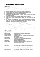
1 FEATURES AND SPECIFICATIONS 1.1 Features This series DVR has the following features: z Bank ATM use and the device can be installed inside of the ATM machine. z H.264 compression algorithm ideal for standalone DVR. z Real-time live display up to 4 cameras, 100/120 fps recording for CIF. z Pentaplex function: live, recording, playback, backup & remote access. z 2 HDDs supported & USB CD-RW/DVD-RW supported.
Video Resolution Video Recording Video Display Split Tour Display Image Quality Privacy Masking Camera Lock Camera Adjustment Video Information Format NTSC PAL CIF 352 *240 352 *288 CIF: PAL 1f/s~25f/s NTSC 1f/s~30f/s Full and multiple screen display: 1 / 4-ch Support 1~6 level (level 6 is the best) Self-defined four-sided zone for privacy masking for each camera Camera locked for users Adjust color according to different time periods Camera title, time, video loss, camera lock, motion detection, recording
Playback Digital Zoom Backup Mode Network Interface Network Functions Remote operation Auxiliary Interface USB Interface RS232 RS485 Environmental Power Supply Power Consumption 2-channel playback simultaneously. Play, pause, stop, rewind, fast play, slow play, next file, previous file, next camera, previous camera, full screen, repeat, shuffle, backup selection.
2 Overview and Controls This section provides information about front panel and rear panel. When you install this series DVR for the first time, please refer to this part first. 2.1 Front Panel These series DVR has two types of front panels. One series front panel is shown as in Figure 2-1. Figure 2-1 1. Upper 2.Left 4. Down 5.Enter 7. Previous 8. Record 10. Assistant 11. Play/Pause 13. Next 14. On/off 16. The second channel indication light 18 Power indications light 3. Esc 6. Right 9.Slow play 12.
1. Record indication light 3. Remote control signal receiver 5. Power button 7. Esc 9. Backward play/Pause/5 11. Slow play/7 13. Previous/9 15. Record 2.Power indication light 4.Switch button 6. Direction buttons/1.2.3.4 8.Enter 10.Play/Pause/6 12.Forward/8 14.Next/0 16.Assitant Please refer to the following sheet for more information. S/N Name 13 Play previous 11 Slow play Icon Function IW When playback, click this button to display previous file. In menu operation, go to previous menu item,.
Working with other keys to realize special functions in some menu items. Cancel 7 Cancel ESC In numeral input mode, Click this button to input 0. In playback mode, click this button to go back to real-time monitor mode. Confirm 8 Confirm Enter Go to the main menu In real-time monitor mode, click left/right direction keys to switch between one-window and multiple-windows. In numeral input mode, Click S to input 6. Increase/decrease numeral In numeral input mode, Click T to input 7.
1 Power socket 2 Power button 3 The third video input channel 4 The third audio input channel. (It is the fourth audio input channel for 4-ch series ATM DVR) 5 The second video input channel 6 The second audio input channel 7 The fitst video input channel 8 The first audio input channel 9 Video output 10 Audio output 11 Network port (RJ45) 12 USB Port 13 VGA port 14 RS232 port 15 ALARM-RS485 port 16 Fan Please refer to Figure 2-4 for AH/AG real panel information.
7 The first video input channel 8 Audio output 9 Video output 10 VGA port 11 RS232 port 12 USB port 13 Networkport(RJ45) 14 ALARM-RS485 port 15 Power button 16 Power socket 2.2.2 Connection Sample Here is a connection sample for your reference. See Figure 2-5.
Figure 2-5 2.3 Remote Control The remote control interface is shown as in Figure 2-6.
Figure 2-6 Serial Number 1 2 3 4 5 6 7 8 9 10 11 12 13 14 15 16 Function remote switch Multiple-window switch 0-9 number key Record Auxiliary key Confirm /menu key Cancel Direction key forward Previous Back Next Slow play Stop Fast play Play/Pause 2.4 Mouse Control Left click System pops up password input dialogue box if you have not logged in. mouse In real-time monitor mode, you can go to the main menu. If you have selected one menu item, left click mouse to view menu content.
In input box, you can select input methods. Left click the corresponding button on the panel you can input numeral/English character (small/capitalized). Here ← stands for backspace button. _ stands for space button. In English input mode: _stands for input a backspace icon and ← stands for deleting the previous character. In numeral input mode: _ stands for clear and ← stands for deleting the previous numeral. When input special sign, you can click corresponding numeral in the front panel to input.
button Page up or page down Move Select current control or move control mouse Drag mouse Select motion detection zone Select privacy mask zone. 2.5 Virtual Keyboard & Front Panel 2.5.1 Virtual Keyboard Input Method The system supports two input methods: numeral input and English character (small and capitalized) input. Move the cursor to the text column, the text is shown as blue, input button pops up on the right.
3 Installation and Connections Note: All the installation and operations here should conform to your local electric safety rules. 3.1 Check Unpacked DVR When you receive the DVR from the shipping agency, please check whether there is any visible damage to the DVR appearance. The protective materials used for the package of the DVR can protect most accidental clashes during transportation. Then you can open the box to check the accessories.
3. Dismantle the HDD bracket. 4. Install the first HDD. Note the HDD is placed upside down. Please make sure bracket is in correct position. 5. Install the second HDD on the bracket. 7. Connect HDD cable to SATA port 6. Fix the HDD bracket into the internal unit. 8. Connect power cord to the HDD. 9. Place the unit cover back and screws firmly. After HDD installation, please check connection of data ribbon and power cord. 3.
Position the unit to allow for cable and power cord clearance at the rear of the unit. Be sure that the air flow around the unit is not obstructed. 3.4.2 Rack Mounting ATM series DVR is suitable for ATM special rack. The dimension is: 200(W)×130 (H)×270mm(L). The extension series support max 4 HDDs. Its dimension is: 200×130×410mm. The DVR occupies two rack units of vertical rack space. The hardware necessary to mount the DVR into a rack is supplied with the unit. Install the cabinet in ventilated place.
Figure 3-1 3.6.2 Connecting Video Output This section provides information about physically connecting video display devices to the DVR. See Figure 3-2. If you connect the DVR with a TV monitor or VGA monitor, the DVR can automatically detects the monitor type. And without any output device, by default, the DVR is configured to use a TV monitor. In this case, if your application requires a VGA monitor, you have to press the button “Fn” or Shift on the front panel to switch.
3.7 Connecting Audio Input & Audio Output, Alarm Input &Alarm Output, RS232/RS485 and Other Interfaces 3.7.1 Audio Input/Audio Output The DVR encodes audio and video signals simultaneously, which lets you control audio at the monitored location. To set up audio: 1. Make sure your audio input device matches the RCA input level. If the device and RCA input levels do not match, audio distortion problems may occur. 2. Make sure the audio connector is wired as follows: 3.
Figure 3-4 3.7.4 Alarm Output Do not connect alarm output port directly with high power load (no more than 1 A) in case of heavy current. You can use the co-contactor to realize the connection between the alarm output port and the load. Please refer to Figure 3-5 for more information. Figure 3-5 3.7.5 Alarm Input and Output Details Please refer to Figure 3-6 for AG/AH series alarm input and output information. The alarm gets activated when the circuit is connected to the ground.
Figure 3-6 z ALARMS1 in 1 to ALARM1 in 4 are corresponding to ALARM1 to ALARM4 respectively. The alarm gets activated in low voltage. z In ALARM1, 1-NO is normal open activation output. In ALARM2, 2-NO C NC is a group of normal open/normal close activation output. z +12V is external alarm input. System needs external device to provide +12V power and you can connect it to the alarm device power below 1A. z A/B is A cable and B cable to control 485 device.
z z z z z z 6: Ctrl 12V(This is used for reset the senor) 485 communication port. They are used to control devices 485 A、B such as PTZ. This should input an external power input(Less than 1 A). +12(C) 4-ch grounding alarm inputs. (Normal open or Normal close type) Please parallel connect COM end and GND end of the alarm detector (Provide external power to the alarm detector). Please parallel connect the Ground of the DVR and the ground of the alarm detector.
Figure 3-10 Relay Specification Model: Material of the contact Rating (resistance load) Insulation Surge voltage Length of open time Length of close time Longevity Temperature JRC-27F Silver Rated switch capacity Maximum switch power Maximum switch voltage Maximum switch currency between contacts with same polarity between contacts with different polarity between contact and winding between contacts with same polarity 3ms max 30VDC 2A, 125VAC 1A 125VA 160W 250VAC, 220VDC 1A 1000VAC 1minute 50/60Hz 1000VA
485 Port 485 Port Figure 3-11 z Connect speed dome video cable to the ATM video input port. z Connect the power to the speed dome. Please refer to chapter 5.3.8 Pan/Tilt/Zoom for PTZ setup information. 3.9 RS232 You can connect the DVR with POS or Keyboard through RS232. With POS system, the DVR can communicate through RS232 and network. For the POS system, the DVR can integrate the text content and even search the record through the info. The series DVR also support NKB operation.
Figure 3-12 32
4 Overview of Navigation and Controls Before operation, please make sure you have properly installed HDDs and all the cable connections. 4.1 Login, Logout & Main Menu 4.1.1 Login When the system boots up, default video display is in multiple-window mode. Click Enter or left click mouse, you can see the login interface. See Figure 4-1. System consists of four accounts: z Username: admin. Password: admin. (administrator, local and network) z Username: 888888. Password: 888888.
Figure 4-2 4.1.3 Logout There are two ways for you to log out. One is from menu option: In the main menu, click shutdown button, you can see an interface is shown as below. See Figure 4-3. Figure 4-3 There are several options for you. See Figure 4-4. Figure 4-4 The other ways is to press power button on the front panel for at least 3 seconds, system will stop all operations. Then you can click the power button in the rear panel to turn off the DVR. 4.1.
Please refer to the following sheet for channel status. stands for opening switch function, stands for closing switch function. 4.2.2 Manual record Note: You need to have proper rights to implement the following operations. Please make sure the HDDs have been properly installed. 4.2.2.1 Manual record menu There are two ways for you to go to manual record menu. z Right click mouse or in the main menu, Advanced->Manual Record.
Figure 4-6 4.2.2.4 Enable all channel recording Highlight ○ below All, you can enable all channel recording. z All channel schedule record Please highlight “ALL” after “Schedule”. See Figure 4-7. When system is in schedule recording, all channels will records as you have previously set (Main menu->Setting->Schedule). The corresponding indication light in front panel will turn on. Figure 4-7 z All channel manual record Please highlight “ALL” after “Manual.” See Figure 4-8.
4.3 Search & Playback 4.3.1 Search Menu There are two ways for you to go to search menu. z Click Pause/Play button in the remote control. z Click search in the main menu. Search interface is shown as below. See Figure 4-10. Usually there are three file types: z R: regular recording file. z A: external alarm recording file. z M: motion detection recording file z C: card and POS test overlay recording file(For some special series only) There are several playback windows. System supports 1/2-ch playback.
6 7 8 9 10 11 12 13 14 Previous frame Next frame Volume Previous file Next channel Next file Previous channel Search Backup 4.3.2 Basic Operation 4.3.2.1 Playback There are various search modes: video type, channel number or time. The system can max display 128 files in one screen. You can use up/down button to turn page. Select the file name and double click mouse (or click enter button), you can view file content. 4.3.2.
In slow playback mode, click this button to switch between play/pause modes. In playback mode, you can click _ 4、Previous/next and ` to view previous or next video in current channel. 4.3.2.
Figure 4-10, system pops up calendar for your reference. Highlighted date means that there are record files in that day. You can click blue date to view file list. In Figure 4-11, there are video files in June 13th and 14th. Double click date to view file list. Figure 4-11 4.4 Record Setup (Schedule) When the system boots up, it is in default 24-hour regular mode. You can set record type and time in schedule interface. 4.4.
z z z Redundancy: System supports redundancy backup function. You can highlight Redundancy button to activate this function. Please note, before enable this function, please set at least one HDD as redundant.(Main menu->Advanced>HDD Management) Snapshoot: You can enable this function to snapshoot image when alarm occurs. Record types: There are three types: regular, motion detection (MD) and Alarm. Please highlight icon to select the corresponding function.
Figure 4-13 Playback or search in the redundant disk. There are two ways for you to playback or search in the redundant disk. z Set redundant disk(s) as read-only disk or read-write disk (Main menu>Advanced->HDD management). See Figure 4-13.System needs to reboot to get setup activated. Now you can search or playback file in redundant disk. z Dismantle the disk and play it in another PC. 4.5 Motion Detect 4.5.
z z z z z button, you can see an interface is shown as in Figure 4-18. Here you can set your own setup for business day and non-business day. Anti-dither: Here you can set anti-dither time. Sensitivity: there are six levels. The sixth level has the highest sensitivity. Alarm output: when alarm occurred, system enables peripheral alarm devices. Tour: Here you can enable tour function when alarm occurs. It is a one-window tour. Please go to chapter 5.3.9 Display for tour interval setup.
Figure 4-16 Figure 4-17 Figure 4-18 4.5.3 Video Loss In Figure 4-14, select video loss in the Type item. You can see the interface is shown as in Figure 4-19.This function allows you to be informed when video loss phenomenon occurred. You can enable alarm output channel and then enable show message function. z Channel: select the channel you want to enable lens shading alarm. z Event type: please select video loss. z Channel: select the channel to record when video loss occurred.
z z z z z z PTZ activation: Here you can set PTZ movement when alarm occurs. Such as go to preset, tour & pattern when there is an alarm. Click “select” button, you can see an interface is shown as in Figure 4-16. Period: Click set button, you can see an interface is shown as in Figure 4-17. Here you can set for business day and non-business day. In Figure 4-17, click set button, you can see an interface is shown as in Figure 4-18. Here you can set your own setup for business day and non-business day.
z z z z z Period: Click set button, you can see an interface is shown as in Figure 4-17. Here you can set for business day and non-business day. In Figure 4-17, click set button, you can see an interface is shown as in Figure 4-18. Here you can set your own setup for business day and non-business day. Sensitivity: there are six levels. The six-level has the highest sensitivity. Alarm output: when alarm occurred, system enables peripheral alarm devices.
z z z z z z z button, you can see an interface is shown as in Figure 4-24. Here you can set your own setup for business day and non-business day. Anti-dither: Here you can set anti-dither time. Show message: System can pop up a message to alarm you in the local host screen if you enabled this function. Send email: System can send out email to alert you when alarm occurs. Record channel: you can select proper channel to record alarm video (Multiple choices).
Figure 4-23 Figure 4-24 4.7 Backup DVR support various backup devices such as CD-RW,DVD driver, USB backup and network download. Here we introduce USB backup first. You can refer to Chapter 7 Web Client Operation for network download backup operation. 4.7.1 Detect Device Here is for you to view devices information. See Figure 4-25. Figure 4-25 4.7.
Select backup device and then channel, file start time and end time. Click add button, system begins search. All matched files are listed below. System automatically calculates the capacity needed and remained. See Figure 4-26. system only backup files with a √ before channel name. You can use Fn or cancel button to delete √ after file serial number. Click backup button, you can backup selected files. There is a process bar for you reference.
For CD/DVD burner device, the stop function becomes activated immediately and there is no data in the burner. z For USB device, system can backup the data before you click stop button. For example, if there is a file of 10 minutes, when you click stop after five minutes backup, system only save the previous 5-minute data in the device. The file name format usually is: SN_CH+channel number+time Y+M+D+H+M+S. In the file name, the YDM format is the same as you set in general interface.
After all the setting please click save button. In one window display mode, right click mouse (click “Fn” Button in the front panel or click “Fn” key in the remote control). The interface is shown as in Figure 4-34. Figure 4-29 Click Pan/Tilt/Zoom, the interface is shown as below. See Figure 4-30. Here you can set the following items: z Speed: value ranges fro 1 to 8. z Zoom z Focus z Iris Click icon and to adjust zoom, focus and iris.
Figure 4-32 Here is a sheet for you reference. Name Function function key Zoom Near Focus Near Iris close Shortcut key ► _ W Function key function Shortcut Key Far Far Open ► f 4.9 Preset/ Patrol/Pattern/Scan In Figure 4-30, click the “set” button. The interface is shown as below. See Figure 4-33. Here you can set the following items: z Preset z Patrol(Tour) z Pattern z Border Figure 4-33 In Figure 4-30, click page switch button, the interface is shown as in Figure 4-34.
Note: The following setups are usually operated in the Figure 4-30,Figure 4-33 and Figure 4-34 . 4.9.1Preset Setup In Figure 4-30, use eight direction arrows to adjust camera to the proper position. In Figure 4-33, click preset button and input preset number. The interface is shown as in Figure 4-35. Now you can add this preset to one patrol (tour). Figure 4-35 4.9.2 Activate Preset In Figure 4-34, please input preset number in the No. blank, and click preset button. 4.9.
Figure 4-37 4.9.6 Activate Pattern Function In Figure 4-34, input mode value in the No. blank, and click pattern button. 4.9.7 Auto Scan Setup In Figure 4-33, click border button. The interface is shown as in Figure 4-38. Please go to Figure 4-30, use direction arrows to select camera left limit Then please go to Figure 4-38 and click left limit button Repeat the above procedures to set right limit. Figure 4-38 4.9.8 Activate Auto Scan In Figure 4-34, click “Auto Scan” button, the system begins auto scan.
5 Understanding of Menu Operations and Controls 5.1 Menu Tree This series DVR menu tree is shown as below. Please note, you need to click Save button at the bottom of the interface to save the setup you have just made. You need to highlight check box enable corresponding function. Otherwise, this function is disabled. All the operations below are based on our 4-ch series DVR. 5.2 Main Menu When you login, the system main menu shows as below. See Figure 5-1 .
Figure 5-1 5.3 Setting In main menu, highlight setting icon and double click mouse. System setting interface is shown as below. See Figure 5-2. Figure 5-2 5.3.1 General General setting includes the following items. See Figure 5-3. z System time: here is for you to set system time z Date format: there are three types: YYYYY-MM-DD: MM-DD-YYYYY or DD-MMYYYY. z Date separator: there are three denotations to separate date: dot, beeline and solidus. z Snapshoot: Here you can set image upload interval.
z z z z z z Language: system supports various languages: Chinese (simplified), Chinese (Traditional), English, Italian, Japanese, French, Spanish (All languages listed here are optional. Slight difference maybe found in various series.) HDD full: Here is for you to select working mode when hard disk is full. There are two options: stop recording or rewrite. Pack duration: Here is for you to specify record duration. Default value is 60 minutes.
5.3.2 Encode Encode setting includes the following items. See Figure 5-6. Please note some series do not support extra stream. z Channel: Select the channel you want. z Compression: system supports H.264. Or you can select from the dropdown list. z Resolution: System supports various resolutions, you can select from the dropdown list. For this model, we can support D1/CIF. z Bit rate: system supports two types: CBR and VBR. In VBR mode, you can set video quality.
Figure 5-6 Figure 5-7 Figure 5-8 For dual-stream series, DVR supports various settings for channel, resolution and frame: Resolution:pixel PAL:QCIF=176×144; CIF=352×288; HD1=352×576; 2CIF=704×288; D1=704×576; NTSC:QCIF=176×120; CIF=352×240; HD1=352×480; 2CIF=704×288; D1=704×480; 59
We take 16-channel DVR as an example. There are four groups:1~4, 5~8, 9~12, 13~16. Please refer to the formula:resolution× frame rate The resources for one group are: PAL: D1×50 or NTSC: D1×60 D1×50(60)F/s=Half-D1×100(120)F/s=CIF×200(240)F/s You can arrange channel parameter within the specified limit.
Figure 5-9 5.3.5 Network Here is for you to input network information. See Figure 5-10. z IP address: Here you can input IP address. z DHCP: It is auto search IP function. When enable DHCP function, you can not modify IP/Subnet mask /Gateway. These values are from DHCP function. If you have not enabled DHCP function, IP/Subnet mask/Gateway display as o. You need to disable DHCP function to view current IP information. Besides, when PPPoE is operating, you can not modify IP/Subnet mask /Gateway.
Figure 5-10 5.3.5.1 Advanced Setup Advanced setup interface is shown as in Figure 5-11. Please draw a circle to enable corresponding function and then double click current item to go to setup interface. Figure 5-11 5.3.5.2 IP Filter IP filter interface is shown as in Figure 5-12. You can add IP in the following list. The list supports max 64 IP addresses. Please note after you enabled this function, only the IP listed below can access current DVR.
Figure 5-12 5.3.5.3 Multiple Cast Setup Multiple-cast setup interface is shown as in Figure 5-13. Figure 5-13 Here you can set a multiple cast group. Please refer to the following sheet for detailed information. z IP multiple cast group address -224.0.0.0-239.255.255.255 -“D” address space z The higher four-bit of the first byte=”1110” z Reserved local multiple cast group address -224.0.0.0-224.0.0.255 -TTL=1 When sending out telegraph -For example 224.0.0.1 All systems in the sub-net 224.0.0.
z Like the single broadcast address of RFC1918 z Can not be used in Internet transmission z Used for multiple cast broadcast in limited space. Except the above mentioned addresses of special meaning, you can use other addresses. For example: Multiple cast IP: 235.8.8.36 Multiple cast PORT: 3666. 5.3.5.4 PPPoE PPPoE interface is shown as in Figure 5-14. Input “PPPoE name” and “PPPoE password” you get from your ISP (Internet service provider).
American Mountain Time(M.T) American Central Time(C.T) American Eastern Time(E.T) Atlantic Time Brazil Middle Atlantic Time GMT-7 GMT-6 GMT-5 GMT-4 GMT-3 GMT-2 Figure 5-15 5.3.5.6 Email Setup Email setup interface is shown as in Figure 5-16. Here you can set email server information. Note: You need to get the email address from your email service provider first. Please use semicolon to separate the addresses. Figure 5-16 5.3.5.7 DDNS Setup DDNS setup interface is shown as in Figure 5-17.
Figure 5-17 5.3.5.8 Alarm Server You can set alarm in accordance with different alarm protocols. System can inform the alarm server when alarm occurs. See Figure 5-18. Figure 5-18 5.3.5.9 FTP You need to download or buy FTP service tool (such as Ser-U FTP SERVER) to establish FTP service. Please install Ser-U FTP SERVER first. From “start” -> “program” -> Serv-U FTP Server -> Serv-U Administator. Now you can set user password and FTP folder. Please note you need to grant write right to FTP upload user.
You can use a PC or FTP login tool to test setup is right or not. For example, you can login user ZHY to FTP://10.10.7.7 and then test it can modify or delete folder or not. See Figure 5-20. Figure 5-20 System also supports upload multiple DVRs to one FTP server. You can create multiple folders under this FTP. In Figure 5-10, select FTP and then double click mouse. You can see the following interface. See Figure 5-21. Figure 5-21 in front of Enable to activate FTP function.
Figure 5-22 File length: upload file length. When setup is larger than the actual file length, system will upload the whole file. When setup here is smaller than the actual file length, system only uploads the set length and auto ignore the left section. z When interval value is 0, system uploads all corresponding files. z Period 1 and period 2: you can set two periods for one each channel. System file name is shown as in Figure 5-23. z Figure 5-23 5.3.6 Alarm Please refer to chapter 4.
Figure 5-24 5.3.9 Display Display setup interface is shown as below. See Figure 5-25. z Transparency: Here is for you to adjust transparency. The value ranges from 128 to 255. z Channel name: Here is for you to modify channel name. Please note all your modification here only applies to DVR local end. You need to open web or client end to refresh channel name. z Time display: You can select to display time or not when system is playback.
Figure 5-25 In Figure 5-25, click modify button after channel. You can see an interface is shown as in Figure 5-26. Please note all your modification here applies to local end only. You need to refresh web or client-end to get the latest channel name. System max support 25-digital character. Figure 5-26 In tour mode, you can see the following interface. On the right corner, right click mouse or click shift button, you can control the tour.
Click default icon, system pops up a dialogue box. You can highlight default factory setup. See Figure 5-28. z Select all z General z Encode z Schedule z RS232 z Network z Alarm z Detect z Pan/tilt/zoom z Display z Channel name to restore Please highlight icon to select the corresponding function. After all the setups please click save button, system goes back to the previous menu.
Figure 5-29 5.5.1 HDD Management Here is for you to view and implement hard disk management. See Figure 5-30. You can set proper mode for each hard disk from the dropdown list. When you use redundant backup function, you can set one or more redundant HDD(s). Please note you need to set at least one read-write disk, otherwise system will not record video. For detailed information you can refer to chapter 4.4 Schedule.
Figure 5-31 5.5.2 Abnormity Abnormity interface is shown as in Figure 5-32. z Event type: There are several options for you such as disk error, no disk and etc. z Alarm output: alarm activation output port (multiple choices), among which is controllable 12V output. z Latch: here you can set corresponding delaying time. The value ranges from 10s300s. System automatically delays specified seconds in turning off alarm and activated output after external alarm cancelled.
Figure 5-33 5.5.4 Manual Record Please refer to chapter 4.2.2 manual record. 5.5.5 Account Here is for you to implement account management. See Figure 5-34. Here you can: z Add new user z Modify user z Add group z Modify group z Modify password. For account management please note: z System account adopts two-level management: group and user. No limit to group or user amount. z For group or user management, there are two levels: admin and user. z The user name and group name can consist of eight bytes.
Figure 5-34 5.5.6 Auto Maintain Here you can set auto-reboot time and auto-delete old files setup. See Figure 5-35. You can select proper setup from dropdown list. After all the setups please click save button, system goes back to the previous menu. Figure 5-35 5.5.7 TV Adjust Here is for you to adjust TV output setup. See Figure 5-36. Please drag slide bar to adjust each item. After all the setups please click OK button, system goes back to the previous menu. Figure 5-36 5.5.
Six frame ID groups verification can guarantee information validity and legal. Figure 5-37 Click Data button you can see an interface is shown as in Figure 5-38. Here you can set some items such as offset, length, title. Figure 5-38 5.6 Information Here is for you to view system information. There are totally five items: HDD (hard disk information), BPS (data stream statistics), Log and version, and online user. See Figure 5-39.
5.6.1 HDD Information Here is to list hard disk type, total space, free space, video start time and status. See Figure 5-40. Note: Please remove the broken hard disk before you add a new one. Once there is a hard disk confliction, please check hard disk time and system time is the same or not. Please go to setting then general to modify system time. At last, reboot the system to solve this problem. If disk is damaged, system shows as “?” Figure 5-40 5.6.
Figure 5-42 5.6.4 Version Here is for you to view some version information. See Figure 5-43. z Channel z Alarm in z Alarm out z System version z Build date: Figure 5-43 5.6.5 Online Users Here is for you to manage online users. See Figure 5-44. You can disconnect one user or block one user if you have proper system right.
Figure 5-44 5.7 Exit Double click exit button, system pop up a dialogue box for you to select. See Figure 5-45. z Logout menu user: log out menu. You need to input password when you login the next time. z Restart application: reboot DVR. z Shutdown: system shuts down and turns off power. z Restart system: system begins rebooting. z Switch user: you can use another account to log in.
6 About Auxiliary Menu 6.1 Go to Pan/Tilt/Zoom Menu In the one-window surveillance mode, right click mouse (click “fn” Button in the front panel or click AUX key in the remote control). The interface is shown as below: See Figure 6-1. Figure 6-1 Click Pan/Tilt/Zoom, the interface is shown as in Figure 6-2. Here you can set the following items: z Zoom z Focus z Iris Click icon and to adjust zoom, focus and Iris.
In the middle of the eight direction arrows, there is a 3D intelligent positioning key. See Figure 6-4 . Click this button, system goes back to the single screen mode. Drag the mouse in the screen to adjust section size. Figure 6-4 Here is a sheet for you reference. Name Function function key Zoom Near Focus Near Iris close Shortcut key ► _ W Function key function Far Far Open Shortcut key ► f 6.2 Preset /Patrol / Pattern /Border Function In Figure 6-2 click the set button.
Figure 6-6 6.2.1 Preset Setup Note: The following setups are usually operated in the Figure 6-2, Figure 6-5 and Figure 6-6. In Figure 6-2, use eight direction arrows to adjust camera to the proper position. In Figure 6-5, click preset button and input preset number. The interface is shown as in Figure 6-7. Add this preset to one patrol number Figure 6-7 6.2.2 Activate Preset In Figure 6-6 please input preset number in the No. blank, and click preset button. 6.2.
Please go to Figure 6-2 to modify zoom, focus, and iris. Go back to Figure 6-9 and click end button. You can memorize all these setups as pattern 1. Figure 6-9 6.2.6 Activate Pattern Function In Figure 6-6 input mode value in the No. blank, and click pattern button. 6.2.7 Border Setup In Figure 6-5, click border button. The interface is shown as in Figure 6-10.
Figure 6-11 84
7 WEB CLIENT OPERATION Please note, all the operation here in chapter seven is based on our 4-ch DVR. Slightly difference maybe found in the user interface. 7.1 Network Connection Before web client operation, please check the following items: z Network connection is right z DVR and PC network setup is right. Please refer to network setup(main menu>setting->network) z Use order ping ***.***.***.***(* DVR IP address) to check connection is OK or not. Usually the return TTL value should be less than 255.
If you can’t download the ActiveX file, please modify your settings as follows. See Figure 7-2. Figure 7-2 After installation, the interface is shown as below. See Figure 7-3. Please input your user name and password. Default factory name is admin and password is admin. Note: For security reasons, please modify your password after you first login.
After you logged in, you can see the main window. See Figure 7-6. This main window can be divided into the following sections. z Section 1: there are five function buttons: configuration (chapter 7.3), search (chapter 7.4), alarm (chapter 7.5), about (chapter 7.6), log out (chapter 7.7). z Section 2: there are channel number and three function buttons: refresh, start dialog and local play. z Section3: there are PTZ (chapter 7.2.2), color (chapter 7.2.
Figure 7-6 7.2.1 Real-time Monitor In section 2, left click the channel name you want to view, you can see the corresponding video in current window. For detailed function key information, please refer to Figure 7-7. 1 2 3 4 5 6 Figure 7-7 1: Digital zoom: Click this button and then left drag the mouse in the zone to zoom in. right click mouse system restores original status. z 2: Change show mode: resize or switch to full screen mode. z 3: Local record.
Figure 7-9 7.2.2 PTZ Before PTZ operation, please make sure you have properly set PTZ protocol. (Please refer to chapter 7.3.2 Setting-> Pan/Tilt/Zoom). Click PTZ button, the interface is shown as in Figure 7-10 . You can click this icon to display or hide the PTZ control platform. Figure 7-10 7.2.2.1 Direction key and 3D positioning key In Figure 7-10, there are eight direction keys. In the middle of the eight direction keys, there is a 3D intelligent positioning key.
Name Function key Function Function key Function Zoom Near Far Focus Near Far Iris close Open Then click triangle icon in Figure 7-10, you can see the following interface. See Figure 7-11. Figure 7-11 In Figure 7-11, click PTZ setup button you can see the following interface. See Figure 7-12.
Figure 7-12 7.2.2.4 Auto Scan In Figure 7-12, move the camera to you desired location and then click left limit button. Then move the camera again and then click right limit button to set a right limit. 7.2.2.5 Pattern In Figure 7-12, you can input pattern value and then click start record button to begin PTZ movement. Please go back to Figure 7-11 to implement camera operation. Then you can click stop record button. Now you have set one pattern. 7.2.2.
Figure 7-13 7.2.3 Color Click color button in section 3, the interface is shown as Figure 7-14. Here you can select one channel and then adjust its brightness, contrast, hue and saturation. (Current channel border becomes green). Or you can click default button to use system default setup. Figure 7-14 7.2.4 Picture Path and Record Path Click more button in Figure 7-14, you can see an interface is shown as in Figure 7-15.
Figure 7-16 Click record path button, you can see an interface is shown as in Figure 7-17. Figure 7-17 7.2.5 Menu Interface Switch Put your mouse on the PTZ control bar until you see the following icon. See Figure 7-18. Figure 7-18 Left click your mouse and then drag it to the channel control status bar. You can see the two menus interface switched. See Figure 7-19. You can compare the following interface with Figure 7-6.
7.3 Configure In the main window, click config button, you can see an interface is shown as in Figure 7-20. Figure 7-20 7.3.1 System Information Click device configuration button, you can see the following interface. See Figure 7-21.
Figure 7-21 z Version Click version button, you can see corresponding HDD information for your reference. See Figure 7-22. Figure 7-22 z HDD Information Here you can view HDD amount, HDD status, total volume and free space. See Figure 7-23.
Figure 7-23 z Log Click log button, you can see an interface is shown as in Figure 7-24. Here you can view current device log information. Figure 7-24 7.3.
Setting includes the following items: General Encode setup Schedule RS232 Network MUL-DDNS FTP Alarm setup Detect Pan/Tilt/Zoom Tool Please note: setups for different device series may vary. Please refer to the corresponding user’s manual. z General General interface is shown as in Figure 7-25. System time: Here is for you to modify system time. Please click Save after your modification Data format: Here you can select data format from the dropdown list.
Figure 7-25 z Encode Encode setup includes the following items. See Figure 7-26. Here you can select Channel: Here is for you to select a channel. Channel name: Modify channel name. Data stream: Regular and extra data stream. AV enable: Video/Audio. System only displays video by default. You need to manually enable audio function. Bit rate: There are two options: CBR and VBR. You can only set video quality in VBR mode.
Figure 7-26 z Schedule Schedule includes the following interface. See Figure 7-27. When DVR boots up, it is in 24-hour continuous record. In this interface you can set record type, record time and period. Record type includes regular record(R), motion detection record (M) and alarm record (A). Channel: select the channel number you desire. Week: you can select from the dropdown list. Or you can select at the bottom of the interface.
Figure 7-27 Figure 7-28 Tip: After you finished setup for one channel, you can click “save as” button, system pops up the following interface. See Figure 7-29.Now you can copy one channel setup to other channels.
Figure 7-29 z Network Network interface is shown as in Figure 7-30. This interface includes the following items: Max: Here you can set max connection amount. The value ranges from 0 to 10. 0 means no network connection is allowed. TCP port: default setup is 37777. Please note port 37778 is for network UDP port use only. HTTP port: default setup is 80. Transfer: here you can select the priority between fluency/video quality.
Enable DDNS You need a PC of fixed IP in the internet and there is the DDNS software running in this PC. In other words, this PC is a DNS (domain name server).see Figure 7-31. Please enable DDNS function and then input PC IP. Click save button and then reboot device. Now you can login via DDNS. Please open IE and then input http: //(DDNS server IP)/ DDNServer / default.htm. for example, input http: //10.5.2.149/DDNServer/default.htm, you open a DDNS server web page.
Figure 7-32 z Mul-DDNS Here you can select DDNS type. This operation needs DVR device supported. See Figure 7-33.
After you completed setup here, system upload scheduled data to the specified FTP server regularly. Need device supported. In Figure 7-34, you need to input FTP server address, port, log in user name and password. Then you need to specify the destination directory to save files. z File: here you can input uploaded file length (Unit: MB) if the file is smaller than the setup value here, system upload the whole file.
Figure 7-35 z Alarm Please note before alarm setup, you need to properly connect alarm input and output device, send address and receive address. Click save button confirm current setup. Alarm setup includes the following items. See Figure 7-36. Event Type: you can select event type from the drop down list: Local alarm/Net alarm. Alarm in: Select corresponding alarm in channel Type: There are two options: normal open and normal close. Record channel: select record channel when alarm occurs.
Figure 7-36 Figure 7-37 z Detect Detect interface is shown as in Figure 7-38. Here includes the following items: Channel: Select channel name from the dropdown list. Type: There are three types: motion detection/Video loss/Camera mask detection. Record channel: Here you can select record channel (Multiple choices).
Period: Here is for you to set record period. Click set button, you can see an interface is shown as in Figure 7-39. In Figure 7-39, click time set button, you can see an interface is shown as in Figure 7-40. Here you can set time period. Sensitivity: There are six levels. The sixth level has the highest sensitivity. Region: If you select motion detection type, you can click this button to set motion detection zone. The interface is shown as in Figure 7-41. There are 192 zones (16*12).
Figure 7-39 Figure 7-40 Figure 7-41 108
Figure 7-42 z Pan/Tilt/Zoom Pan/Tilt/Zoom interface is shown as in Figure 7-43. Please note you have properly set dome address and all connections are right. Decoder: Select the dome connected channel. Protocol: select the corresponding dome protocol.(such as Pelco) Address: Set corresponding dome address. Default value is 1. Please note your setup here shall comply with your dome address; otherwise you can not control the speed dome. Baud rate: Select the dome baud rate. Default setup is 9600.
Save configuration data: Click export config button to save current setup as a file. Extension name is CFG. See Figure 7-45. Load configuration data: Click import config button, you can load a setup file. Figure 7-44 Figure 7-45 7.3.2.1 Advanced Advanced includes the following items. See Figure 7-46. Account HDD management Alarm input Alarm output Auto maintain Video matrix Snapshoot z Account Account interface is shown as in Figure 7-46.
Figure 7-46 Click add group button, you can see the following interface. See Figure 7-47. Here you can add one new group, and then select corresponding rights for the whole group accounts.
Figure 7-47 Click add user button, you can see the following interface. See Figure 7-48. Here you can input a new user and then select corresponding rights. Please note one user must belong to one group and user right shall not exceed group rights limit.
Figure 7-48 z Record Control Record control interface is shown as in Figure 7-49. Record control: Here you can enable record status for corresponding channel. Alarm output channel: Here you can select alarm output channel. DVR output channel can not support large overload. (It shall be less than 1A). Too heavy current may result in relay damage. Please use contactor if necessary. Figure 7-49 z HDD management This function needs DVR device supported.
Figure 7-50 z Auto maintenance Auto maintenance interface is shown as in Figure 7-51. Here you can enable auto reboot or auto delete old files function.
Video matrix interface is shown as in Figure 7-52. Please note this function needs DVR supported. Figure 7-52 z Snap Picture Snapshoot interface is shown as in Figure 7-53. Please note this function needs DVR supported.
7.4 Search Here you can select video type, channel number and time to search the file you want. Click search button, the interface is shown as below. See Figure 7-54 Please use page up/down key to view the search results. Double click file name, you can view the file and system will automatically backup the image in you installation directory. Figure 7-54 In the search result interface, you can select one or more files to download to your local PC. The playback bar is shown as below. See Figure 7-55.
Figure 7-55 7.4.1 Download You can select one or more files you want to download and then click down load button. System pops up a dialogue box asking you specify directory. See Figure 7-56. Figure 7-56 Then you can input file name and click save to backup file in your local pc. During the download process, there is a process bar for you reference and you can see download button becomes stop button. See Figure 7-57.
Figure 7-57 7.5 Alarm Here you can set alarm type and alarm prompt audio file. See Figure 7-58. Figure 7-58 7.6 About Click about button, you can view current web client information. See Figure 7-59.
Figure 7-59 7.7 Log out Click log out button, system goes back to log in interface. See Figure 7-60. Figure 7-60 7.8 Un-install Web Control You can use web un-install tool “uninstall web.bat” to un-install web control. Please note, before you un-installation, please close all web pages, otherwise the un-installation might result in error.
8 Enterprise Professional Surveillance System In this chapter, we introduce how to add devices and how to enable monitor function. For detailed operation, please refer to enterprise professional surveillance system user’s manual. 8.1 Log in Double click enterprise profession surveillance platform icon ( ).If it is your first time to use the system, you can see the following interface. See Figure 8-1. Figure 8-1 After selecting a language, you can see the following interface.
Figure 8-2 8.2 Enable Monitor After successfully logged in, please select the device and then click connect/disconnect button( ). Select the channel you wan to view, click connect/disconnect button( Section 1 ) again.
Figure 8-3 There are totally six sections: z Section 1: There are eight function keys: monitor, E-map, record, save, alarm, configuration, log and system. z Section 2: Here is for you to view channel video. z Section 3: Here is for you to select display mode. System supports various display modes. HD item is for you to select priority between real-time and video fluency. z Section 4: Here is for you to view current help information. z Section 5: Here is to display data flux and CPU status.
Add organization structure Add device Figure 8-5 124
9 RS232 Operation 9.1 Network Connection Before serial port operation, please connect matrix with DVR through RS232. Then set DVR serial port protocol to the corresponding matrix protocol. Note: please contact you local retail to confirm the DVR supports matrix protocol or not. 9.2 Keyboard Control keyboard is very convenient for multi-DVR control, menu options and PTZ control. Select keyboard control from system setting>RS232 >function, and then set concerning attributes such as protocol.
10 FAQ 1. DVR can not boot up properly. There are following possibilities: z Input power is not correct. z Power connection is not correct. z Power switch button is damaged. z Program upgrade is wrong. z HDD malfunction or something wrong with HDD ribbon. z Seagate DB35.1,DB35.2,SV35 or Maxtor 17-g has compatibility problem. Please upgrade to the latest version to solve this problem. z Front panel error. z Main board is damaged. 2. DVR often automatically shuts down or stop running.
6. Can not search local records. There are following possibilities: z HDD ribbon is damaged. z HDD is broken. z Upgraded program is not compatible. z The recorded file has been overwritten. z Record function has been disabled. 7. Video is distorted when searching local records. There are following possibilities: z Video quality setup is too low. z Program read error, bit data is too small. There is mosaic in the full screen. Please restart the DVR to solve this problem. z HDD data ribbon error.
z z When there are several decoders, please add 120 Ohm between the PTZ decoder A/B cables furthest end to delete the reverberation or impedance matching. Otherwise the PTZ control is not stable. The distance is too far. 12. Motion detection function does not work. There are following possibilities: z Period setup is not correct. z Motion detection zone setup is not correct. z Sensitivity is too low. z For some versions, there is hardware limit. 13. Can not log in client-end or web.
z z z z z Burner and DVR are in the same data cable. System uses too much CPU resources. Please stop record first and then begin backup. Data amount exceeds backup device capacity. It may result in burner error. Backup device is not compatible. Backup device is damaged. 17. Keyboard can not control DVR. There are following possibilities: z DVR serial port setup is not correct z Address is not correct z When there are several switchers, power supply is not enough. z Transmission distance is too far. 18.
z z z z There is no media player. No DXB8.1 or higher graphic acceleration software. There is no DivX503Bundle.exe control when you play the file transformed to AVI via media player. No DivX503Bundle.exe or ffdshow-2004 1012 .exe in Windows XP OS. 23. Forget local menu operation password or network password Please contact your local service engineer or our sales person for help. We can guide you to solve this problem. Slight difference may be found in user interface.
Appendix A HDD Capacity Calculation Calculate total capacity needed by each DVR according to video recording (video recording type and video file storage time). Step 1: According to Formula (1) to calculate storage capacity qi that is the capacity of each channel needed for each hour, unit Mbyte.
Appendix B Compatible USB Drive List NOTE: Please upgrade the DVR firmware to latest version to ensure the accuracy of the table below. If you use the USB drive, please confirm the format FAT or FAT32.
Appendix C Compatible CD/DVD Burner List NOTE: Please upgrade the DVR firmware to latest version to ensure the accuracy of the table below. And you can use the USB cable with the model recommended to set USB burner.
Appendix D Compatible SATA HDD List NOTE: Please upgrade the DVR firmware to latest version to ensure the accuracy of the table below. And SATA HDD should be used for the DVR with SATA port. Manufacturer Series Model Capacity Type Seagate Barracuda.10 ST3750640AS 750G SATA Seagate Barracuda.10 ST3500630AS 500G SATA Seagate Barracuda.10 ST3400620AS 400G SATA Seagate Barracuda.10 ST3320620AS 320G SATA Seagate Barracuda.10 ST3250620AS 250G SATA Seagate Barracuda.10 ST3250820AS 250G SATA Seagate Barracuda.