User’s Manual For BMM V3.0 / MB V3.0 / VAWS V3.0 / POR V3.0 / VOL V3.0 / OP V3.0 / LR V3.0 / US V3.0 / FR V3.0 / JP V3.0 / FA V3.0 / KR V3.0 / CR V3.0 Multi-system Car Diagnostic Tool series PROFESSIONAL . FAST . SMART .
EN Contents 1 PRODUCT DESCRIPTIONS .................................................................. 1 2 SPECIFICATIONS ................................................................................... 2 3 ACCESSORIES INCLUDED .................................................................. 2 4 PRODUCT FEATURES ........................................................................... 2 5 VEHICLE COVERAGE............................................................................
EN 6.2.18 Seat ............................................................................................. 39 6.3 BATTERY VOLTAGE TEST ....................................................................... 40 6.4 OBDII / EOBD ...................................................................................... 40 6.5 DTC LOOKUP......................................................................................... 41 6.6 REVIEW AND REPORT ..............................................................
EN Multi-system Car Diagnostic Tool series 1 Product Descriptions Serial Number 1 2 3 4 5 6 Button Name Description BACK Button UP Button LEFT Button RIGHT Button DOWN Button ENTER Button 7 HELP Button 8 F1 Function Button Returns to previous menu Moves cursor up for selection Moves cursor left for selection Moves cursor right for selection Moves cursor down for selection Confirms a selection (or action) from a menu list Shows help information for test results or user operation.
EN 9 10 11 12 2 F2 Function Button OBDII Connector Storage Card Slot DATA Cable Connector In case of special use Connects the scan tool to the vehicle’s Data Link Connector via OBDII Cable Holds the system of the scan tool. Connects the scan tool for power supply and update the software if needed. Specifications Item Display Operation Temperature Storage Temperature Operating Voltage Operating Current Power Consumption Dimension Weight 3 Description 4.
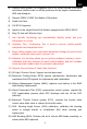
EN 1) iCarsoft Multi-system Car Diagnostic tool V3.0 Series can do it all-reads and clears trouble codes on all the systems such as engine ,transmission, ABS and airbag etc. 2) Support OBDII / EOBD Ten Modes of Operation. 3) Read Live Data. 4) Full ECU Diagnosis. 5) Applies to the single Brand of all Models equipped with OBDII-16DLC. 6) Easy To Use with Silicone Keys. 7) Auto identify technology can automatically identify model and year information in no time.
EN 19) Injector Coding (INJ), relearn the injector control parameter while the injector renewed or replaced. 20) Head Lamp is about the headlamp maintenance, maintenance and other related operations (including AFS setting), and then perform this function for calibration. 21) Air Suspension: After maintenance, replacement and other operations of the suspension height sensor are performed in all aspects, this function needs to be executed for suspension learning and calibration.
EN 32) DTC Library to lookup when user is operating this tool. 33) Upgrade Via PC. 34) Multi-language: English, German, Dutch, Spanish, French. Note: Certain functions may be limited from the vehicle manufacturer due to the requirement of a special factory access code. This scan tool covers over 20 years of models, so some functions may not be available on all years / models. 5 Vehicle Coverage iCarsoft Multi-system Car Diagnostic Tool V3.
EN the scan tool connected power. Make sure the ignition is ON when you connected the scan tool already. Note: For vehicles manufactured by different vendors, it is possible that it has different diagnostic menus. For details, please follow the instructions on the screen to proceed. 6.1 Diagnose This function is specially designed to diagnose electronic control system of single vehicle model connected the scan tool already.
EN The “VIN identify” can automatically parse the car model, eliminating the cumbersome program manually input by the user. The device diagnostic system has the latest automatic identification function based on the vehicle identification number. It stores all the diagnosable electronic control units of Scan on the vehicle and performs the diagnosis on the selected system. Perform automatic VIN recognition.
EN 6.1.1.3 Vehicle Select When the vehicle cannot be retrieved automatically through the ECU of the vehicle, or the specific VIN is unknown, you can manually select the vehicle. Or in some cases, when the user selects vehicle selection rather than vehicle VIN scanning, the system will provide the option of vehicle selection, and the user can select the vehicle model, model year, etc. according to his own model.
EN 1) Quick test Scan the control unit of the whole vehicle, At the same time, the fault information of each control unit is detected to show the control unit list and fault status. Left side --- Show vehicle control unit number and system name. Right side --- Show vehicle control unit status. Fault | 5 : Indicates that the fault code is detected; 5 represents the number of faults detected. Pass: Indicates that the vehicle is equipped with this system and has no fault code.
EN Note: If quick test is performed first and then auto scan is performed, the diagnostic status will be memorized. 3) Control Unit This option allows you to manually locate the desired control system. According to the menu driven program, the user manually selects the specified control unit that he wants to detect, skips the whole vehicle scanning, and directly carries out the diagnosis of the specified system.
EN 3. Clear fault memory --- Use this function to clear the original fault code after reading the vehicle fault code and completing the repair. 4. View data --- When this function is selected, the data list of the selected module will be displayed on the screen. 5. Actuation Test --- This function provides access to vehicle specific subsystem tests and component tests. 6.
EN you can save these data by press [REC]. Read fault code --- This function reads and displays the fault codes retrieved from the vehicle control system. Read the fault code of all electronic system module, display the fault status and description code. In addition, you can press [REC] to save the fault information. The "read fault code" interface varies according to the test vehicles, and some vehicles can also read frozen frame data.
EN the figure below. Clear fault memory – After reading the vehicle fault code and completing the repair, this function can be used to clear the original fault code. Before clearing the fault code, make sure the vehicle engine is off and the ignition key is in the on (run) position. Erase full electronic system module fault code and diagnostic related freeze frame information.
EN between different vehicles. Read full electronic system module live data by text value or waveform. Also you can save these data by press [REC]. When there is [W] in the upper right corner of the data stream, select [WAVE] to display the waveform, as shown in the following figure: Actuation Test --- The "Actuation Test" function accesses vehicle specific subsystem tests and performs component tests.
EN To perform signal turn signal lamp action test (take left turn signal lamp as an example): 1) Enter the action test and select left turn signals. 2) At this time, the signal indicator is not running. 3) Press the [Start] button to execute the action. 4) At this time, the signal indicator is running, indicating that the action is being executed. Press the [stop] button to stop.
EN Focus on the following three functions: Sliding Roof Basic Setting After the maintenance of the skylight, it is necessary to use the basic setting to re match and learn the stop point value of the automatic skylight at each position. To Preform Sliding Roof Basic Setting: 1) Sliding roof basic setting is required after the maintenance of the sunroof,access basic settings,select Sliding Roof Basic Setting. 2) The basic settings of the sliding roof is closed.
EN value of the automatic sunroof at each position. 5) At this time, various actions of the sunroof will be executed. The status on the screen changes to “ON”. Note: marked means that the information here is pressed [?] button to see all information.
EN 2) Read the information on the screen: when the speed reaches 15 km/h, the doors will lock automatically. 0 is off, 1 is on. 3) Input “1”, and press the button [Save]. The status on the screen changes to “Success”. Remote Control Adaptation After clearing all the learned remote control information data (generally, remote key will be invalid), it is necessary to use this function to restore the key remote control function.
EN iCarsoft V3.0 Multi-system Car Diagnostic Tool Series provide Oil Reset, EPB, BMS, DPF, ETC, SAS, Bleeding, Injector and more service functions for most modern vehicles on the road today. Select Service function from Main menu to access these special functions. Whether the vehicle has service function depends on the vehicle brand. Select the "Service" function to quickly access the vehicle system and match various special functions.
EN 3) Enter the required mileage after oil change and press [OK] to next step until the application is completed. Press [OK] to exit. Set the number of days since last oil change: 1) Select the "Days since last oil change" option in the function list. Turn on the vehicle ignition. 2) Wait for communication between vehicle and equipment. When the interface of data stream appears, press [OK] to next step.
EN 3) Enter the number of days after oil change and press the [OK] to next step until the application is completed. Press [OK] to exit. 6.2.2 EPB Electronic Parking Brake (EPB) system maintenance, deactivates and reactivates the EPB system for replacement and initialization (Take Jaguar as a sample). 1) Select the "EPB" icon in the service function icon, Select the correct vehicle according to the on-screen instructions.
EN 4) As shown in the figure below, make sure that the parking brake is switched on and the shift lever is in N gear. Operate the clutch as required when the engine is running. 5) Press the [OK] to next step until the calibration is successful, fully depress the clutch pedal, select neutral and release the clutch pedal. 6) The screen prompts that the application is complete, and press [OK] to exit. 6.2.
EN vehicle according to the on-screen instructions. 2) Select the "battery - battery replacement" option in the function list, and a operator message will appear on the screen: this operation will re store the internal battery monitoring data. Press [OK] to continue. 3) Until the screen prompts the application to complete. The operation is completed. 4) Press [OK] to exit. 6.2.
EN 3) Follow the instructions on the screen step by step, and start the vehicle to drive at a speed higher than 40 km for about 15 minutes. Drive the vehicle to the required speed and press the "OK" button when the speed is reached. 4) Subsequent procedures will force the engine management system to perform a diesel particulate filter regeneration. 5) Regeneration is completed when it is indicated that the soot mass in the particulate filter is now at an acceptable lower limit.
EN 6) Application completed, press OK to exit. 6.2.6 SAS SAS: Steering Angle Sensor (SAS) calibration, calibrates the steering wheel to straight ahead, or recalibrates SAS while steering part replacement (Take Jaguar as a sample). If the steering column or instrument cluster is replaced or the instrument cluster software is updated, a body system steering column calibration is required.
EN 4) In the next step of system communication, until the application program is completed. Press [OK] to exit. 6.2.5 ETC Electronic Throttle Control system (ETC), relearns the throttle valve control value while clear or replace the throttle valve (Take Benz as a sample). 1) Select the "ETC" icon in the service function icon, Select the correct vehicle according to the on-screen instructions. 2) Learn the throttle valve stop point value.
EN Note: marked means that the information here is pressed [?] button to see help information. As shown in the figure below: 4) Press the [Yes] button to perform the learning process. Until the application is complete, press [OK] to exit. 6.2.
EN 2) Turn on the ignition switch and perform the brake exhaust procedure as required. Carefully read the operator information that appears on the screen. Note that this function cannot be operated while moving the vehicle. 3) Turn on the left front exhaust screw as required by the screen and keep pressing the brake pedal. Follow the instructions on the screen. After a certain period of time, release the brake pedal and close the front exhaust screw. The operation is complete.
EN operation of the fuel injector, you need to carry out this operation to replace the fuel injector code. 1) Select the "Injector" icon in the service function icon, Select the correct vehicle according to the on-screen instructions. 2) Select the "Powertrain Set - Up - Injector Replacement" option in the function list. The screen indicates that the injector configuration value needs to be updated. 3) Follow the screen operation step by step, press the [OK] to perform the next step.
EN to call up the input box and input the identification number. 6) Press [OK] to complete the execution. You can perform the next injector code change or exit application. 6.2.9 Head Lamp Head Lamp is about the headlamp maintenance, maintenance and other related operations (including AFS setting), and then perform this function for calibration. (Take Jaguar as a sample). If the vehicle has a headlamp replacement, the calibration of the headlamp leveling height sensor needs to be performed.
EN 3) Wait for the system communication, keep the vehicle stationary as required, and press [OK] to perform the system calibration operation. This process takes 30 seconds. 4) Wait until the screen prompts "application completed" to complete the operation, and press [OK] to exit. 6.2.10 Air Suspension Air Suspension: After maintenance, replacement and other operations of the suspension height sensor are performed in all aspects, this function needs to be executed for suspension learning and calibration.
EN 3) Carefully read the operation information on the screen, and press the operation step by step to select the [OK] to continue. Note that in some processes, the suspension height will change, and the engine should be turned off, and the power supply voltage is 12.5V. 4) If the conditions are met, the system will enter the communication state, and the air suspension will enter inflation until the process is completed, and the system will prompt to turn off the ignition. 6.2.
EN accessed by reading directly from the wheel unit or by using the identification reading tool. On completion, a specific road test will be required followed by the tire pressure monitor system confirmation application. 1) Select the TPMS icon in the service function icon or the TPM option in service in diagnostic mode. Select the correct vehicle according to the on-screen instructions.
EN After the refrigerant, blower pump, etc. in the air conditioner are replaced, the air conditioning system may not work normally. At this time, this function is needed to activate the air conditioner for a period of time to match the replaced refrigerant, blower pump and other automotive components. (Take Benz as a sample). 1) Select the "Air-conditioner" icon in the service function icon, Select the correct vehicle according to the on-screen instructions.
EN 1) Select the "Fuel pump" icon in the service function icon, Select the correct vehicle according to the on-screen instructions. 2) Select Activate fuel pump. 3) Follow the prompts on the screen until the operation is completed. 4) Press [OK] to exit. 6.2.14 Engine Idle This correction can be executed when the idle speed fault is resolved. Adjust the engine speed of the car at idle speed. (Take Benz as a sample).
EN 3) Press the [reduce] or [increase] button to adjust the engine idle speed. 4) Follow the prompts on the screen until the operation is completed. 5) Press [OK] to exit. 6.2.
EN 4) Press [OK] to the next step, this process takes a long time, until the completed instruction is prompted. 5) Press [OK] to exit. 6.2.16 Air Filter The engine is a very precise machine part, and even the smallest impurities will cause the wear of the engine. Therefore, the air must be filtered by the air cleaner before entering the cylinder. Therefore, the disassembly, maintenance or replacement of the air filter will cause some particulate impurities in the air to enter the car parts.
EN 3) Follow the prompts Until the instruction to complete the command operation appears. 4) Press [OK] to exit. 6.2.17 Door After repairing or replacing the window lift motor, it is necessary to perform relevant functions for calibration (Take Jaguar as a sample). Door Window Calibration: This routine learns the top position of the door window glass, which enables pinch protection and one touch up function. The door window glass position can be learned by executing this routine.
EN 4) Until the screen prompts that the operation is completed, press the OK to exit. 6.2.18 Seat After repairing or replacing the seat position drive motor, it is necessary to perform relevant functions for calibration (Take Jaguar as a sample). Driver's Seat Calibration: The following routine will restore all the seat axis position values to default for the driver's seat module. 1) Select "Seat" icon in service function icon, Select the correct vehicle according to the on-screen instructions.
EN Passenger's Seat Calibration: The following routine will restore all the seat axis position values to default for the passenger seat module. Note: Different models will have different menu modes. This manual is for reference. Everything in kind shall prevail. If there is any increase or decrease in the function of the product, the actual product shall prevail. 6.
EN 6.5 DTC Lookup Use cursor button to select DTC Lookup icon from the main screen, press ENTER. Press LEFT / RIGHT button to move the highlight bar to different position. Press UP / DOWN button to alter the value, and press ENTER button, the screen will display definition of the DTC. 6.6 Review and Report Use the cursor button to select the Review icon from the main screen, press ENTER to review data. The saved data also can be uploaded to PC by data cable and create report document on PC. 6.7 Setup 6.
EN 6.7.2 Unit of Measure On Tool Setup, use DOWN button to select Unit of Measure and press ENTER, where you can choose Metric or Imperial. 6.7.3 Buzzer On Tool Setup, use DOWN button to select Buzzer and press ENTER, where you can turn the buzzer ON or OFF. 6.7.4 LOG On Tool Setup, use DOWN button to select Log and press ENTER, where you can turn the Log ON or OFF. Set to ON, the log function is enable. RECORD function will be disable. The log function will be disable after reboot.
EN 6.8 Help Use cursor button to select Help icon on the main screen, press ENTER. 6.9 About Use cursor button to select About icon on the main screen, press ENTER. On the Tool Information page, there are software version, hardware version and product serial number etc.. 7 Warranty 7.
EN above limitations may not apply to you. 7.2 Service Procedures If you have any questions, please contact your local store, distributor or visit our website www.icarsoft.us / www.icarsoft.com .If it becomes necessary to return the Diagnostic Tool for repair, contact your local distributor for more information. 8 Software Update&Data Print Software Update allows you to update the scanner’s software through a PC / laptop (With Windows Operation System).
EN 3) Connect PC / Laptop Connect the scanner to PC via data cable (if you have a TF card reader, you can also update via TF card reader),PC will recognize one more removable U-disc.
EN 4) Start application Run the application iCarsoft_MSDIAG_PCClientkits on your PC, the application will recognize the scanner by SN. 5) Upgrade Press Download button to start software upgrade, when the update process is completed, it will come up with an update successful message.
EN 8.2 Data Print Procedures: 1) Save data User can press [RECORD] button to save the diagnosis data such as Module Information, Live Data, Fault, Data, Freeze Frame and Vehicle Information etc., the data will be saved as *.rex file on the TF memory card, these files can be used to create diagnosis report by the application iCarsoft_MSDIAG_PCClientKits. 2) Supposed the application iCarsoft_MSDIAG_PCClientKits has already being installed correctly, If NOT, please refer to above” Update Procedures”.
EN 4) Select files BMW_EN_TEST_0001 shows all recorded data with BMW Diagnosis Software. OBD_EN_TEST_0001 shows all recorded data with OBD Diagnosis Software. Click the *.
EN [CLEAR] button to clear all data in the edit area. [SAVE] button to save all data in the edit area as a text file. [PREVIEW] button for printer-preview. [PRINT] button to print all data in the edit area.
iCarsoft Technology Inc. www.icarsoft.us www.icarsoft.