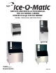
SERVICE AND INSTALLATION MANUAL THE ICE SERIES CUBERS ICE0250 through ICE2100 SERIES* *Includes Undercounter and 22 Inch Series ICE-O-Matic 11100 East 45th Ave Denver, Colorado 80239 Part Number 9081270-01 Date 1/08
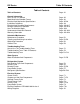
ICE Series Notes Table of Contents Table of Contents Page A1 General Information How To Use This Manual Model And Serial Number Format Electrical And Mechanical Specifications Installation Guidelines Electrical And Plumbing Requirements Remote Condenser Installation How The Machine Works Undercounter Model Bin Removal Warranty Information Page Page Page Page Page Page Page Page Page A2 A3 A5-A8 A9 A10-A17 A18-A19 A20 A21-A22 A23-A24 Scheduled Maintenance Maintenance Procedure Cleaning and Sanitizing
ICE Series Table Of Contents Table of Contents Table of Contents Page A1 General Information How To Use This Manual Model And Serial Number Format Electrical And Mechanical Specifications Installation Guidelines Electrical And Plumbing Requirements Remote Condenser Installation How The Machine Works Undercounter Model Bin Removal Warranty Information Page Page Page Page Page Page Page Page Page A2 A3 A5-A8 A9 A10-A17 A18-A19 A20 A21-A22 A23-A24 Scheduled Maintenance Maintenance Procedure Cleaning and
ICE Series General Information How To Use This Manual Ice-O-Matic provides this manual as an aid to the service technician in installation, operation, and maintenance of the ICE Series (electro-mechanical) cube ice machines. If used properly this manual can also assist the service technician to troubleshoot and diagnose most of the problems that may occur with the machine. The first two sections of this manual provide general information and maintenance information.
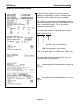
ICE Series General Information Model and Serial Number Format Model Numbers ICE 040 0 H A Condenser Type: A=Air W=Water R=Remote T=Top Discharge Air Cooled Cube Size: H=Half (3/8 X 7/8 X7/8) F=Full (7/8 X 7/8 X7/8) Voltage: 0=115V 5=240/50/1 6=208-230/60/1 7=208-230/60/3 Approximate 24 hour ice production: (x 10 @ 70°F/21°C Air and 50°F/10°C Water) Series: Slab ice cuber, Stainless Steel Cabinet Serial Number Date Code The first letter in the serial number indicates the month and decade of manufacture.
ICE Series General Information Model and Serial Number Format Since all Enodis companies will eventually be utilizing same operating system, a company wide format for serial numbers has been designed. This format is 14 characters long and begins with a date code followed by the Ice-O-Matic identifier, and then a sequential number. This is an entirely numerical serial number. The new serial number will look like the example. 0407 1280 010123 010123 is the serial identifier. 1280 is the identifier.
ICE Series General Information Voltage Model ICEU150*A1 ICEU150*W1 ICEU150*A2 ICEU150*W2 ICEU150*A3 ICEU150*W3 ICEU200*A1 ICEU200*W1 ICEU200*A2 ICEU200*W2 ICEU220A ICEU220W ICEU206*A1 ICEU206*W1 ICEU226A ICEU226W ICEU300A ICEU300W ICE0250*A3 ICE0250*A-T3 ICE0250*W3 ICE0250*A4 ICE0250*A-T4 ICE0250*W4 ICE0320*A1 ICE0320*W1 ICE0320*A2 ICE0320*W2 ICE0320*A3 ICE0320*W3 ICE0400*A1 ICE0400*A-T1 ICE0400*W1 ICE0400*A2 ICE0400*A-T2 ICE0400*W2 ICE0400*A3 ICE0400*A-T3 ICE0400*W3 ICE0406*A1 ICE0406*W1 ICE0406*A2 ICE04
ICE Series General Information Voltage Model ICE0500*A1 ICE0500*A-T1 ICE0500*W1 ICE0500*R1 ICE0500*A2 ICE0500*A-T2 ICE0500*W2 ICE0500*R2 ICE0500*A3 ICE0500*A-T3 ICE0500*W3 ICE0500*R3 ICE0500*R4 ICE0520*A1 ICE0520*W1 ICE0520*A2 ICE0520*W2 ICE0520*A3 ICE0520*W3 ICE0606*A1 ICE0606*A-T1 ICE0606*W1 ICE0606*R1 ICE0606*A2 ICE0606*A-T2 ICE0606*W2 ICE0606*R2 ICE0606*R3 ICE0606*A3 ICE0606*A-T3 ICE0606*W3 ICE0606*R4 ICE0806*A1 ICE0806*W1 ICE0806*R1 ICE0806*A2 ICE0806*W2 ICE0806*R2 ICE0806*R3 ICE1006*A1 ICE1006*W1 IC
ICE Series General Information Model ICE1406*A1 ICE1406*W1 ICE1406*R1 ICE1406*A2 ICE1406*W2 ICE1406*R2 ICE1406*A3 ICE1406*W3 ICE1406*R3 ICE1407*A1 ICE1407*W1 ICE1407*R1 ICE1407*A2 ICE1407*W2 ICE1407*R2 ICE1407*A3 ICE1407*W3 ICE1407*R3 ICE1506*R ICE1506*R ICE1606*R1 ICE1806*W1 ICE1806*R1 ICE1806*W2 ICE1806*R2 ICE1806*W3 ICE1806*R3 ICE1807*W1 ICE1807*R1 ICE1807*W2 ICE1807*R2 ICE1807*W3 ICE1807*R3 ICE2106*W1 ICE2106*R1 ICE2106*W2 ICE2106*R2 ICE2106*W3 ICE2106*R3 ICE2107*W1 ICE2107*R1 ICE2107*W2 ICE2107*R2 V
ICE Series 50 hz.
ICE Series General Information Installation Guidelines Note: Installation should be performed by an Ice-O-Matic trained Service Technician. For proper operation of the Ice-O-Matic ice machine, the following installation guidelines must be followed. Failure to do so may result in loss of production capacity, premature part failures, and may void all warranties. Ambient Operating Temperatures Minimum Operating Temperature: 50°F (10°C) Maximum Operating Temperature 100°F (38°C), 110°F (43°C) on 50 Hz.
ICE Series General Information Electrical and Plumbing Requirements: ICEU150, ICEU220, ICEU205 and ICEU206 Page A10
ICE Series General Information Electrical and Plumbing Requirements: ICEU150, 220, 225 and 226 Note: The ICEU150, ICEU220, ICEU225 and ICEU226 do not have a splash curtain. These models utilize a thermostatic bin control in place of a mechanical bin switch.
ICE Series General Information Electrical and Plumbing Requirements: ICEU300 and 305 Note: The ICEU300 does not have a splash curtain. This model utilize a thermostatic bin control in place of a mechanical bin switch.
ICE Series General Information Electrical and Plumbing Requirements: ICE0250, ICE0400, ICE0500, ICE0606, ICE0806 and ICE1006 (30 Inch Wide Cubers) Page A13
ICE Series General Information Electrical and Plumbing Requirements: ICE1406, ICE1806, ICE2106 (48 Inch Wide Cubers) Prior to January 2008 Page A14
ICE Series General Information Electrical and Plumbing Requirements: ICE0320 and ICE0520 (22 Inch Wide Cubers) Page A15
ICE Series General Information Electrical and Plumbing Requirements: ICE1400, ICE1800 and ICE2100 Revision 3 (From January 2008) Page A16
ICE Series General Information Electrical and Plumbing Requirements: ICE1506 Remote Page A17
ICE Series General Information Remote Condenser Installation For proper operation of the Ice-O-matic ice machine, the following installation guidelines must be followed. Failure to do so may result in loss of production capacity, premature part failure, and may void all warranties. Installation Guidelines Ambient operating temperatures: -20°F (-28.9°C) to 120°F (48.9°C) Maximum refrigerant line length: 60 ft. (18.29 Meters) Maximum vertical rise: 16 ft. (4.
ICE Series General Information The following remote ice makers incorporate the mixing valve in the condenser. This configuration allows up to a 100 foot calculated remote line set run. Reference the diagram below to calculate the maximum 100 foot line set run.
ICE Series General Information How the ICE Machine Works A general description of how the ICE Series cubers work is given below. The remainder of the manual provides more detail about the components and systems. With the ICE/OFF/WASH switch in the ICE position, the compressor, water pump and condenser fan motor (when applicable) will energize starting the freeze cycle. During the freeze cycle, water is circulated over the evaporator(s) where the ice cubes are formed.
ICE Series General Information Undercounter Bin Removal-ICEU300 Series The storage bin can be removed by: 1 Remove the lower grill. 2. Remove two screws securing bin to cabinet base. 3. Remove the thumbscrews from the back wall of the bin. 4. Disconnect bin drain. 5. Lift front of bin slightly and pull bin forward to remove.
ICE Series General Information Undercounter Bin Removal-ICEU150/200 Series The storage bin can be removed by: 1. Remove the two screws at the rear of the top panel. 2. Remove the two screws from the front panel. 3. Remove two screws securing bin to cabinet base. 4. Disconnect bin drain. 5. Lift front of bin slightly and pull bin forward to remove.
ICE Series General Information Warranty Information Every Ice-O-Matic machine is backed by a warranty that provides both parts and labor coverage.
ICE Series General Information Ice-O-Matic Parts and Labor Domestic & International Limited Warranty Mile High Equipment LLC (the “Company”) warrants Ice-O-Matic brand ice machines, ice dispensers, remote condensers, water filters, and ice storage bins to the end customer against defects in material and factory workmanship for the following: • Cube ice machines,”GEM” model compressed ice machines ,” MFI” model flake ice machines and remote condensers.
ICE Series Scheduled Maintenance Maintenance Note: Maintenance should be performed by an Ice-O-Matic trained Service Technician. Electrical shock and/or injury from moving parts inside this machine can cause serious injury. Disconnect electrical supply to machine prior to performing any adjustments or repairs. Failure to perform the required maintenance at the frequency specified will void warranty coverage in the event of a related failure.
ICE Series Scheduled Maintenance Cleaning and Sanitizing (continued) 5. Add recommended amount of approved Nickel Safe ice machine cleaner to the water trough according to label instructions on the container. 6. Initiate the wash cycle at the ICE/OFF/WASH switch by placing the switch in the “WASH” position. Allow the cleaner to circulate for approximately 15 minutes to remove mineral deposits. 7.
ICE Series Winterizing Procedures Winterizing Procedures Important! Whenever the ice machine is taken out of operation during the winter months, the procedure below must be performed. Failure to do so may cause serious damage and will void all warranties. 1. Turn off water to machine. 2. Make sure all ice is off of the evaporator(s). If ice is being made, initiate harvest or wait for cycle completion. 3. Place the ICE/OFF/WASH switch to the “OFF” position. 4.
ICE Series Cabinet Care Cleaning stainless steel Commercial grades of stainless steel are susceptible to rusting. It is important that you properly care for the stainless steel surfaces of your ice machine and bin to avoid the possibility of rust or corrosion. Use the following recommended guidelines for keeping your stainless steel looking like new: 1. Clean the stainless steel thoroughly once a week. Clean frequently to avoid build-up of hard, stubborn stains.
ICE Series Troubleshooting Trees How To Use The Troubleshooting Trees The troubleshooting trees were developed to be used in conjunction with the service information in the sections that follow. If used together as intended, these two parts of the manual will allow the ice machine service technician to quickly diagnose many of the problems encountered with the ice machines.
ICE Series Troubleshooting Trees Troubleshooting Trees Table Of Contents Machine Does Not Run C3 Machine Runs, Does Not Make Ice C4 – C5 Slow Production (Cube Formation Good) C6 Low Suction Pressure C7 High Suction Pressure C8 Cubes Are Hollow C9 Uneven Bridge Thickness C10 Ice Bridge Thickness Varies Cycle To Cycle C11 Machine Produces Cloudy Ice C12 Poor Water Distribution Over Evaporator C13 Machine Does Not Enter Harvest C14 Machine Enters Harvest, Then Returns To Freeze Prematur
ICE Series Troubleshooting Trees Machine Does Not Run Is the selector switch set to ICE? YES Check for correct power supply to the machine NOT OK Correct field wiring deficiency OK NO Set selector Switch to the ICE position Check High Pressure Safety Control TRIPPED Reset and identify reason for high head pressure OK Check High Temperature Safety Control OPEN Replace or identify reason for being open.
ICE Series Troubleshooting Trees Machine Runs, Does Not Make Ice YES Is water running over the evaporator? GO TO PAGE C5 Is the compressor running? NO NO Go to the Troubleshooting Tree on page C12 Check for power to the compressor contactor coil GOOD Check contactor for bad contactor or coil.
ICE Series Troubleshooting Trees Machine Runs, Does Not Make Ice (continued) Is water leaking out of the Purge Drain or Water Trough? NO Check refrigerant pressures, see page E1 HIGH OR NORMAL SUCTION LOW SUCTION YES Recover and weigh in refrigerant charge OK Repair water leakage defect Low side restriction or defective TXV Page C5 If head pressure is also high, make sure Condenser is clean and machine has good air flow OK Check Hot Gas Valve for leakage during freeze, see page E5 OK Check
ICE Series Troubleshooting Trees Slow Production (Cube Formation Good) Does installation meet guidelines? YES OK Check for excessive head pressure Check refrigeration system, Section E NO Correct any installation defects TOO HIGH AIR Is this unit air cooled or water cooled? Is the Air Condenser clean? YES Check refrigeration system, Section E NO WATER Clean Condenser and Condenser Fan Blade Check Water Regulating Valve, See page E2 NOT OK OK See Condenser service information page E2 Page C
ICE Series Troubleshooting Trees Low Suction Pressure Does installation meet guidelines? NO Correct deficiency in installation NO Go to Troubleshooting Tree on page C12 YES Is the water flow over the Evaporator correct? YES NOT OK Check for correct head pressure, see page E10 NO Is the machine a remote unit? Low charge, locate and repair leak, evacuate and recharge system YES See Troubleshooting Tree page C18 OK Check TXV for moisture based restriction DRY SYSTEM Check for refrigerant tu
ICE Series Troubleshooting Trees High Suction Pressure Have you checked the “Slow Production” Tree? NO Go to “Slow Production” Troubleshooting Tree Replace Compressor YES NOT OK NO Is the head pressure also high? OK Check Hot Gas Valve, see page E5 Check Compressor, see page E1 OK YES NOT OK TXV could be defective, see Expansion Valve, see page E3 and E4 Hot Gas Valve is possibility defective Is the machine installed to specifications? NO Correct installation defects YES Repair or replace
ICE Series Troubleshooting Trees Cubes Are Hollow Is the water temperature above 100°F (38°C)? YES Water temperature too high, correct water temperature NO Is there good water flow over the Evaporator? YES Is water leaking from the Purge Drain? YES Purge Valve has an obstruction or could be defective NO NO OK Go to the “Poor Water Distribution Over Evaporator” Troubleshooting Tree, page C13 Check Timer for proper setting, see page F4 NOT OK Timer Initiate Control out of adjustment of defect
ICE Series Troubleshooting Trees Uneven Bridge Thickness Make sure supply water temperature is below 100°F (38°C) OK Is water running into the bin? YES Problem in water system, see pages D1 and D2.
ICE Series Troubleshooting Trees Ice bridge Thickness Varies Cycle To Cycle Is air and water temps consistent and within guidelines? NO Correct installation deficiency YES Check the Purge Valve for water leaks NOT OK Clean Purge Valve or replace if defective OK Check Hot Gas valve for proper operation NOT OK Replace Hot Gas Valve OK Check Timer Initiate Control for proper operation NOT OK Replace Timer Initiate OK Check Solid State Timer for proper operation NOT OK Adjust Timer or replace i
ICE Series Troubleshooting Trees Machine Produces Cloudy Ice Is water running evenly across the evaporator? NO See “Poor Water Running Over Evaporator Troubleshooting Tree page C13 NO Correct installation deficiency YES Doe machine meet installation guidelines? See Section A YES Cloudiness is a result of properties in the incoming supply water Page C12
ICE Series Troubleshooting Trees Poor Water Distribution Over The Evaporator YES Is the machine level? NO Level the machine Is the water level in the Water Trough correct? See Section D NO Is the supply water pressure correct? YES NO Correct deficiency in supply water pressure YES Purge valve stuck open, clean or replace if defective YES Check Water Distribution Tube for obstructions or improper assembly See Section D Is water leaking from the Purge Drain? NO OBSTRUCTED Clean Water Distri
ICE Series Troubleshooting Trees Machine Does Not Enter Harvest Will suction pressure drop below cut-in of Timer Initiate? NO NO Is the freeze pattern on the Evaporator even? Check Purge Valve to make sure it is not leaking, if it is replace valve or remove obstruction OK Hot Gas Valve could be leaking YES OK YES Does the manual Purge Switch energize the Purge Valve? OK Check for signs of a weak Compressor, see page E1 Make sure system is not overcharged YES NOT OK Check Timer Initiate Contr
ICE Series Troubleshooting Trees Machine Enters Harvest, Then Returns To Freeze Prematurely Is the Harvest Assist working properly? See page F6 YES Check the Manual Purge Switch Normally Closed contacts. See page F1 OPEN Purge Switch is defective CLOSED NO Adjust as required or replace defective part Check High Temperature Safety Control.
ICE Series Troubleshooting Trees Length Of Harvest Excessive Does the machine meet installation guidelines? NO Correct installation deficiency OK Is the ice formation even on the Evaporator? YES Check Harvest Assist Assembly for proper operation, see page F6 NO Low refrigerant charge, repair leak and weigh in proper charge NOT OK YES Adjust or replace defective part Does the machine have a remote condenser? YES Remote: Check Mixing Valve operation, page E6 Water Cooled: check Water Valve for
ICE Series Troubleshooting Trees Ice Does Not Release From Evaporator Is the ice bridge correct? See page F4 YES NO Is the machine level? Level the machine YES NO Does water run over the Evaporator during harvest? Set proper bridge thickness, see page F4 Clean the Evaporator, see page B2 NO OK Check Harvest Assist for proper operation, see page F6 YES NOT OK OK Check Purge valve and Tubing for obstructions and proper operation, see page D2 NOT OK Replace Purge Valve or repair tubing obstru
ICE Series Troubleshooting Trees Hot Evaporator, Low Suction And Discharge Pressure (Remote Only) Does the machine meet the installation guidelines? NO Correct installation deficiency YES Does the machine have the proper refrigeration charge? YES Mixing Valve may be defective, see page E6 NO Repair leak, evacuate and weigh in refrigerant charge per nameplate Page C18
ICE Series Water System Water Distribution and Components Water enters the machine through the float valve located in the water trough. The water trough holds water used for ice making. The float valve is used to maintain the proper water level in the water trough. During the freeze cycle water is continuously circulated over the evaporator by the water pump. When the machine enters harvest, the purge valve (not shown) opens and mineral laden water is pumped out of the water trough to the drain.
ICE Series Water System Water Distribution Tube Water is pumped to a distribution tube located at the top of the evaporator and is used to distribute water evenly over the evaporator. The distribution tube can be removed and dissembled for cleaning if the hole becomes plugged or if there is excessive mineral build-up in the water system. The water distribution tube is a tube within a tube. Water enters and fills the inner tube and exits through a series of holes along the top of the inner tube.
ICE Series Water System Water Splash Curtain The water splash curtain covers the evaporator to prevent water from splashing into the bin and is also used to actuate the bin switch. When the bin becomes full of ice, the splash curtain is held open when the ice drops off of the evaporator. The actuator tab or wire bale on the splash curtain will release pressure on the bin switch and the machine shuts off. See bin control on page F9.
ICE Series Water System Water Purge Valve When the machine enters the harvest cycle, the water pump continues to run and the purge valve opens. This allows mineral laden water to be pumped from the water trough to the drain. This helps keep the water system clean. The water pump and purge valve de-energizes once the water is flushed from the water trough. The cam switch controls the length of time that the water pump and purge valve remains energized see page F7.
ICE Series Water System Water Trough The water trough can be easily removed by the following procedures: ICEU150/200 Models 1. Disconnect power to the ice machine. Mounting Screws 2. Shut the water supply off to the ice machine. 3. Remove water splash curtains when applicable. 4. Remove water trough mounting screws. 5. Carefully remove water trough from the ice machine. 6. Reverse procedure to reassemble.
ICE Series Refrigeration System Refrigerant Cycle and Components Before diagnosing the refrigeration system, it is very important that the refrigerant charge be correct. Whenever the refrigeration system has been opened, the filter-drier must be replaced and the proper refrigerant charge must be weighed in. See refrigerant charge data on page A5–A8. Refrigerant Pressures The suction pressure at the beginning of the freeze cycle can vary +/- 10 psi (.7 bar) depending on operating conditions.
ICE Series Refrigeration System Refrigerant Refrigerant in a high-pressure liquid form is fed to an expansion valve where the refrigerant is reduced to a low-pressure liquid. Under this low pressure, the liquid will absorb heat from the evaporator causing the liquid to change to a vapor. This vapor is then drawn into the compressor where the temperature and pressure of the vapor are increased.
ICE Series Refrigeration System Thermostatic Expansion Valve (TXV) The thermostatic expansion valve meters the flow of refrigerant into the evaporator changing its state from a high-pressure liquid to a low-pressure liquid. This drop in pressure causes the refrigerant to cool. The cooled refrigerant absorbs heat from the water circulating over the evaporator. As the evaporator fills with liquid refrigerant, the evaporator becomes colder.
ICE Series Refrigeration System Thermostatic Expansion Valve (Continued) A dual evaporator machine will have one TXV for each evaporator. If one TXV sticks open and the other is operating normally, the suction pressure will be higher than normal and both evaporators will build thick ice. It is recommended that both valves be replace if one sticks open.
ICE Series Refrigeration System Note: Permanent discoloration of the evaporator plating is normal and will cause no problems with harvesting the ice or sanitary conditions. Before condemning the evaporator for plating problems, be certain it is not just discoloration. Good evaporators will not be covered under warranty. If the spillway (plastic evaporator top) becomes damaged, it can be replaced. It is not necessary to replace the entire evaporator.
ICE Series Refrigeration System Remote Condenser (Continued) If the airflow is restricted or the condenser is dirty, the head pressure will be excessively high, slow production will result and the compressor may overheat and eventually become damaged. The condenser coil and fan blades must be kept clean. The condenser can be cleaned with compressed air or by using a brush. If a brush is used, brush in the direction of the fins taking care not to bend the fins.
ICE Series Refrigeration System Pump Down System (Remote Only) The pump down system prevents liquid refrigerant from migrating to the evaporator and compressor during the off cycle and prevents the compressor from slugging or starting under an excessive load. Liquid Line Solenoid When a machine with a remote condenser shuts off, the liquid line solenoid valve, located at the outlet of the receiver, is de-energized causing the valve to close completely restricting the flow of refrigerant.
ICE Series Refrigeration System Refrigerant Refrigerant in a high-pressure liquid form is fed to an expansion valve where the refrigerant is reduced to a low-pressure liquid. Under this low pressure, the liquid will absorb heat from the evaporator causing the liquid to change to a vapor. This vapor is the drawn into the compressor where the temperature and pressure of the vapor are increased.
ICE Series Refrigeration System If the refrigeration system is extremely wet, use radiant heat to raise the temperature of the system. This action will cause the moisture to vaporize at less of a vacuum. The use of two (2) valves, one between the vacuum pump and gauge manifold and the other between the refrigerant cylinder and the gauge manifold allows you to evacuate and charge the system without disconnecting any hoses.
ICE Series Refrigeration System Electrical and Mechanical Specifications, “ICE” Series 60 Cycle Machine Model ICEU150*A1 ICEU150*W1 ICEU150*A2 ICEU150*W2 ICEU150A3 ICEU150W3 ICEU200*A1 ICEU200*W1 ICEU200*A2 ICEU200*W2 ICEU220A ICEU220W ICEU206*A1 ICEU206*W1 ICEU226A ICEU226W ICEU300A ICEU300W ICE0250*A2 ICE0250*A-T2 ICE0250*W2 ICE0250*A4 ICE0250*A-T4 ICE0250*W4 ICE0320*A1 ICE0320*W1 ICE0320*A2 ICE0320*W2 ICE0320*A3 ICE0320*W3 ICE0400*A1 ICE0400*A-T1 ICE0400*W1 ICE0400*A2 ICE0400*A-T2 ICE0400*W2 ICE0400*A
ICE Series Refrigeration System Electrical and Mechanical Specifications, “ICE” Series 60 Cycle Machine Model ICE0500*A1 ICE0500*A-T1 ICE0500*W1 ICE0500*R1 ICE0500*A2 ICE0500*A-T2 ICE0500*W2 ICE0500*R2 ICE0500*R3 ICE0500*A3 ICE0500*A-T3 ICE0500*W3 ICE0500*R4 ICE0520*A1 ICE0520*W1 ICE0520*A2 ICE0520*W2 ICE0520*A3 ICE0520*W3 ICE0606*A1 ICE0606*A-T1 ICE0606*W1 ICE0606*R1 ICE0606*A2 ICE0606*A-T2 ICE0606*W2 ICE0606*R2 ICE0606*R3 ICE0606*A3 ICE0606*A-T3 ICE0606*W3 ICE0606*R4 ICE0806*A1 ICE0806*W1 ICE0806*R1 IC
ICE Series Refrigeration System Head Press. Approx.
ICE Series Model ICEU305A ICEU305W ICE0305*A2 ICE0305*W2 ICE0305*A4 ICE0305*W4 ICE0325*A1 ICE0325*A2 ICE0325*A3 ICE0405*A1 ICE0405*W1 ICE0405*A2 ICE0405*W2 ICE0405*A2 ICE0405*W2 ICE0405*A3 ICE0405*W3 ICE0525*A1 ICE0525*A2 ICE0525*A3 ICE0605*A1 ICE0605*W1 ICE0605*R1 ICE0605*A2 ICE0605*W2 ICE0605*R2 ICE0605*R3 ICE0605*A3 ICE0605*W3 ICE0605*R4 ICE0805*A1 ICE0805*W1 ICE0805*R1 ICE0805*A2 ICE0805*W2 ICE0805*R2 ICE0805*R3 ICE1005*A1 ICE1005*W1 ICE1005*R1 ICE1005*A2 ICE1005*W2 ICE1005*R2 ICE1005*R3 ICE1405*A1 ICE1
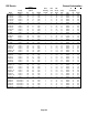
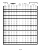
ICE Series Refrigeration System ICEU150A Ambients °F Compressor Temps °F Discharge Suction Refrigeration Pressures PSIG Discharge Suction Cycle Times Minutes' Seconds" Air/Water Start End Start Freeze End Freeze Start Harv End Harv Start End Start End Freeze Harvest Complete 50/40 70/50 90/70 108/98 167 228 305 400 150 205 262 325 59 72 89 107 35 41 43 44 83 104 126 126 93 118 150 183 125 145 165 183 153 177 201 229 43 55 68 88 24 29 35 36 18'11" 23'05" 37'32" 84'18" 1'56" 1'
ICE Series Refrigeration System ICEU226A Ambients °F Compressor Temps °F Discharge Suction Refrigeration Pressures PSIG Discharge Suction Cycle Times Minutes' Seconds" Air/Water Start End Start Freeze End Freeze Start Harv End Harv Start End Start End Freeze Harvest Complete 50/40 70/50 90/70 110/100 183 265 330 435 164 225 275 363 57 69 81 92 38 35 36 43 80 102 117 145 83 111 138 169 109 127 141 169 138 171 189 223 44 58 71 88 26 31 35 47 10'54" 19'50" 26'32" 53'17" 1'40" 1'
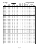
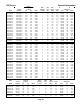
ICE Series Refrigeration System ICE0320W Ambients °F Compressor Temps °F Discharge Suction Refrigeration Pressures PSIG Discharge Suction Cycle Times Minutes' Seconds" Air/Water Start End Start Freeze End Freeze Start Harv End Harv Start End Start End Freeze Harvest Complete 70/50 90/70 110/100 252 254 325 244 246 268 63 75 101 25 28 30 94 108 151 99 115 173 121 134 130 165 178 201 44 61 83 30 40 57 10'57" 12'43" 17"51" 0'55" 0'50" 0'40" 11'53" 13'33" 18'31" ICE0400A3 Ambie
ICE Series Refrigeration System ICE0500W3 Ambients °F Compressor Temps °F Discharge Suction Refrigeration Pressures PSIG Discharge Suction Cycle Times Minutes' Seconds" Air/Water Start End Start Freeze End Freeze Start Harv End Harv Start End Start End Freeze Harvest Complete 50/40 70/50 90/70 110/100 250 250 250 314 250 250 250 277 56 61 69 82 31 31 33 33 85 90 105 145 89 95 113 152 116 121 127 136 171 177 187 212 46 52 63 86 26 28 35 43 9'55" 11'17" 13'24" 20'26" 1'19" 1'10
ICE Series Refrigeration System ICE0606A3 Ambients °F Air/Water 50/40 70/50 90/70 110/100 Compressor Temps °F Discharge Suction Refrigeration Pressures PSIG Discharge Suction Start End 198-270 cycling 270 316 415 205 260 319 Cycle Times Minutes' Seconds" Start Freeze End Freeze Start Harv End Harv Start End Start End Freeze Harvest Complete 51 51 62 80 29 27 32 34 86 80 103 132 95 86 113 143 108 107 122 132 157 159 182 206 51 51 66 88 36 37 48 59 7'51" 9'48" 13'40" 26'37" 0'48"
ICE Series Refrigeration System ICE0806W Ambients °F Compressor Temps °F Discharge Suction Refrigeration Pressures PSIG Discharge Suction Cycle Times Minutes' Seconds" Air/Water Start End Start Freeze End Freeze Start Harv End Harv Start End Start End Freeze Harvest Complete 70/50 90/70 110/100 250 250 321 250 250 293 59 61 78 34 34 35 72 79 108 76 88 121 103 105 116 159 165 193 43 49 65 27 32 45 8'36" 10'52" 18'32" 2'01" 1'10" 0'55" 10'37" 12'02" 19'27" ICE0806R Ambients °
ICE Series Refrigeration System ICE1006R Ambients °F Compressor Temps °F Discharge Suction Refrigeration Pressures PSIG Discharge Suction Cycle Times Minutes' Seconds" Air/Water Start End Start Freeze End Freeze Start Harv End Harv Start End Start End Freeze Harvest Complete -20/40 70/50 90/70 120/100 240 270 287 419 240 266 272 323 61 72 77 93 33 34 33 28 94 107 111 135 101 112 117 150 104 115 118 128 159 173 182 221 53 58 60 77 38 42 43 43 6'44" 8'36" 10'21" 24'34" 0'55" 0'
ICE Series Electrical System Control Circuit All machines in this manual are electro-mechanical controlled; however the control circuitry on the single evaporator units differs from the dual evaporator units and is detailed below. Selector Switch The selector switch is used to put the machine into the ICE making or WASH cycle or to turn the machine OFF. The WASH position allows only the water pump to run and is used during the cleaning process to circulate cleaning solution throughout the water system.
ICE Series Electrical System Compressor Check (Continued) If all starting components are good, check the voltage from the common terminal of the compressor, making sure proper voltage is supplied to the compressor and all wiring is properly connected. If the compressor does not start and there is excessive amperage draw, (see locked rotor amps on compressor tag) the compressor has a locked rotor and should be replaced.
ICE Series Electrical System Untimed Freeze Cycle During the freeze cycle the compressor, water pump and condenser fan motor(s) (if used) are running. On remote systems the liquid line solenoid is also energized, see Refrigeration System. As ice forms on the evaporator, the suction pressure drops. The machine is in the untimed portion of the freeze cycle and will remain in untimed freeze until the suction pressure drops low enough to close the timer initiate control.
ICE Series Electrical System Timed Freeze When the freeze timer is energized, the machine is in the timed portion of the freeze cycle. The freeze timer will time out the remainder of the freeze cycle. Once the time has passed, the machine will enter the harvest cycle. Freeze Timer The freeze time is an adjustable timer used to control the ice bridge thickness. The freeze timer is factory set but may need to be adjusted upon initial start up of the machine.
ICE Series Electrical System Harvest Cycle Single Evaporator Machines Once the freeze timer has timed out, power is sent to relay 1 and the machine enters the harvest cycle. Once in harvest motor, the purge valve, hot gas valve and harvest motor are energized. The water pump continues to run during the first part of the harvest cycle so that mineral laden water remaining in the water trough can be pumped through the purge valve to the drain.
ICE Series Electrical System Harvest Assist Assembly The harvest assist assembly has several purposes: to assist in moving the ice off of the evaporator, to control the length of harvest and to terminate harvest. When the machine enters harvest, power is sent to the harvest motor which turns a slip clutch. A probe is attached to the rotating clutch and is pushed against the back of the ice slab. The clutch begins to slip when the probe applies approximately 25 ounces of pressure against the ice slab.
ICE Series Electrical System Probe Tip and Swivel The probe tip is attached to the clutch and makes contact with the back of the ice slab during harvest. The swivel allows the probe tip to pivot as the clutch turns so that the probe is pushed straight through the evaporator probe guide. The tip of the probe should be flush with the back of the evaporator or recessed up the 1/16 of an inch (.16cm). The probe tip must not extend into the freezing area of the evaporator during freeze.
ICE Series Electrical System Cam Switch Adjustment Check the cam switch for proper adjustment by slowing turning the clutch by hand in a counterclockwise direction while listening for the switch contacts to change. The switch should have an audible “click” as the roller reaches the high part of the cam. Now slowly turn the clutch in a clockwise direction and the switch should have an audible “click” as the roller reaches the low part of the cam.
ICE Series Electrical System Undercounter machines: A thermostatic bin control is used on the undercounter models. The bin thermostat is located in the control box with a capillary tube, which is in a brass thermo-well mounted to the water trough. When ice comes in contact with the capillary tube thermo-well, the bin thermostat opens and the machine will shut off.
ICE Series Electrical System Electrical Sequence for the ICE1400 Series Version 3, ICE1800 Series Version 3 and the ICE2100 Series Version 3 Cubers. (Manufactured from January, 2008) ICE1400A/W3, 1800W3 and 2100W3 Electrical Sequence (Includes 50 hz. And 3 Phase) 1. Suction Pressure starts out at approx 60 psi and slowly drops to close the LP Control. 2. The LP Control energizes Relay Number 2 Coil. 3.
ICE Series Electrical System Electrical Sequence for the ICE1400 Series Version 3, ICE1800 Series Version 3 and the ICE2100 Series Version 3 Cubers. (Manufactured from January, 2008) ICE1400R3, 1800R3 and 2100R3 Electrical Sequence (Includes 50 hz. And 3 Phase) This unit incorporates a timer upstream of the Low Pressure Control for Low Ambients. 1. Timer number 2 (Six Minutes) is energized from the Selector Switch through Relay Number 3B contacts C and NC. 2.
ICE Series Electrical System Electrical Sequence for theICE1506 Series Version 3 (Manufactured from January, 2008) This unit incorporates a timer upstream of the Low Pressure Control for Low Ambients. 1. When the Selector Switch is set to ICE, Relay Number 2 Coil is energized through Cam Switch contacts C and NC (Bypasses the Bin Controls) 2. Relay Number 4B contacts C and NC energize Timer Number 2 (6 Minutes) 3. Timer number 2 times out and energizes Relay Number 3 Coil. 4.
ICE Series Wiring Diagram ICEU150/200/205/206 Air and Water Wiring Diagram Page G1
ICE Series Wiring Diagram ICEU150/200/205/206 Air and Water Wiring Schematic Page G2
ICE Series Wiring Diagram ICEU150/220/225/226 Air and Water Wiring Diagram Page G3
ICE Series Wiring Diagram ICEU150/220/225/226 Air and Water Wiring Schematic Page G4
ICE Series Wiring Diagram ICE0250 Air and Water Wiring Diagram Page G5
ICE Series Wiring Diagram ICE0250 Air and Water Wiring Schematic Page G6
ICE Series Wiring Diagram ICE0400 Air and Water Wiring Diagram Page G7
ICE Series Wiring Diagram ICE0400 Air and Water Wiring Schematic Page G8
ICE Series Wiring Diagram ICE0405/0406 Air and Water Wiring Diagram Page G9
ICE Series Wiring Diagram ICE0405/0406 Air and Water Wiring Schematic Page G10
ICE Series Wiring Diagram ICE0500 Air and Water Wiring Diagram Page G11
ICE Series Wiring Diagram ICE0500 Air and Water Wiring Schematic Page G12
ICE Series Wiring Diagram ICE0500 Remote Wiring Diagram Page G13
ICE Series Wiring Diagram ICE0500 Remote Wiring Schematic Page G14
ICE Series Wiring Diagram ICE0605/0606/0805/0806/1005/1006 Air and Water Wiring Diagram Page G15
ICE Series Wiring Diagram ICE0605/0606/0805/0806/1005/1006 Air and Water Wiring Schematic Page G16
ICE Series Wiring Diagram ICE0605/0606/0805/0806/1005/1006 Remote Wiring Diagram Page G17
ICE Series Wiring Diagram ICE0605/0606/0805/0806/1005/1006 Remote Wiring Schematic Page G18
ICE Series Wiring Diagram ICE1007 Air and Water Wiring Diagram Page G19
ICE Series Wiring Diagram ICE1007 Air and Water Wiring Schematic Page G20
ICE Series Wiring Diagram ICE1007 Remote Wiring Diagram Page G21
ICE Series Wiring Diagram ICE1007 Remote Wiring Schematic Page G22
ICE Series Wiring Diagram ICE1405/1406/1806/2005/2106 Air and Water Wiring Diagram Page G23
ICE Series Wiring Diagram ICE1405/1406/1806/2005/2106 Air and Water Wiring Schematic Page G24
ICE Series Wiring Diagram ICE1405/1406/1806/2005/2106 Remote Wiring Diagram Page G25
ICE Series Wiring Diagram ICE1405/1406/1806/2005/2106 Remote Wiring Schematic Page G26
ICE Series Wiring Diagram ICE1407/1807/2107 Air and Water Wiring Diagram Page G27
ICE Series Wiring Diagram ICE1407/1807/2107 Air and Water Wiring Schematic Page G28
ICE Series Wiring Diagram ICE1407/1807/2107 Remote Wiring Diagram Page G29
ICE Series Wiring Diagram ICE1407/1807/2107 Remote Wiring Schematic Page G30
ICE Series Wiring Diagram ICE1606 Remote Wiring Diagram Page G31
ICE Series Wiring Diagram ICE1606 Remote Wiring Schematic Page G32
ICE Series Wiring Diagram ICE0320 Air and Water Wiring Diagram Page G33
ICE Series Wiring Diagram ICE0320 Air and Water Wiring Schematic Page G34
ICE Series Wiring Diagram ICE0520 Air and Water Wiring Diagram Page G35
ICE Series Wiring Diagram ICE0520 Air and Water Wiring Schematic Page G36
ICE Series Wiring Diagram ICE0325/0525 Air and Water Wiring Diagram Page G37
ICE Series Wiring Diagram ICE0325/0525 Air and Water Wiring Schematic Page G38
ICE Series Wiring Diagram ICE0305 Air and Water Wiring Diagram Page G39
ICE Series Wiring Diagram ICE0305 Air and Water Wiring Schematic Page G40
ICE Series Wiring Diagram ICE1506 Remote Page G41
ICE Series Wiring Diagram ICE1506 Remote Page G42
ICE Series Wiring Diagram ICEU300 Air and Water Page G43
ICE Series Wiring Diagram ICEU300 Air and Water Page G44
ICE Series Wiring Diagram ICEU305 Air and Water Page G45
ICE Series Wiring Diagram ICEU305 Air and Water Page G46
ICE Series Wiring Diagram ICE0500 Remote Wiring Diagram (R3) Page G47
ICE Series Wiring Diagram ICE0500 Remote Wiring Schematic (R3) Page G48
ICE Series Wiring Diagram ICE0605/0606/0806/1006 Remote Wiring Diagram (R3) Page G49
ICE Series Wiring Diagram ICE0605/0606/0806/1006 Remote Wiring Schematic (R3) Page G50
ICE Series Wiring Diagram ICE1007 Remote Wiring Diagram (R3) Page G51
ICE Series Wiring Diagram ICE1007 Remote Wiring Schematic (R3) Page G52
ICE Series Wiring Diagram ICE0250 Air4 and Water4, ICE0400 Air3 and Water3 Wiring Diagram Page G53
ICE Series Wiring Diagram ICE0250 Air4 and Water4, ICE0400 Air3 and Water3 Wiring Schematic Page G54
ICE Series Wiring Diagram ICE0320 Air3 and Water3, ICE0520 Air3 and Water3 Wiring Diagram Page G55
ICE Series Wiring Diagram ICE0320 Air4 and Water4, ICE0520 Air3 and Water3 Wiring Schematic Page G56
ICE Series Wiring Diagram ICE0406/405 Air3 and Water3, ICE0305 Air3 and Water3 Wiring Diagram Page G57
ICE Series Wiring Diagram ICE0406/405 Air3 and Water3, ICE0305 Air3 and Water3 Wiring Schematic Page G58
ICE Series Wiring Diagram ICE0325 Air3 and Water3, ICE0525 Air3 and Water3 Wiring Diagram Page G59
ICE Series Wiring Diagram ICE0325 Air3 and Water3, ICE0525 Air3 and Water3 Wiring Schematic Page G60
ICE Series Wiring Diagram ICE0500 Air3 and Water3 Wiring Diagram Page G61
ICE Series Wiring Diagram ICE0500 Air3 and Water3 Wiring Schematic Page G62
ICE Series Wiring Diagram ICE0500 Remote4 Wiring Diagram Page G63
ICE Series Wiring Diagram ICE0500 Remote4 Wiring Schematic Page G64
ICE Series Wiring Diagram ICE0606 Air3 and Water3, ICE0605 Air3 and Water3 Wiring Diagram Page G65
ICE Series Wiring Diagram ICE0606 Air3 and Water3, ICE0605 Air3 and Water3 Page G66
ICE Series Wiring Diagram ICE0606 Remote4 and ICE0605 Remote4 Wiring Diagram Page G67
ICE Series Wiring Diagram ICE0606 Remote4 and ICE0605 Remote4 Wiring Schematic Page G68
ICE Series Wiring Diagram ICE0606 Remote4 and ICE0605 Remote4 Wiring Schematic Page G68
ICE Series Wiring Diagram ICE1405/6A3/W3, ICE1806W3 and ICE2106W3 Wiring Diagram Page G69
ICE Series Wiring Diagram ICE1405/6A3/W3, ICE1806W3 and ICE2106W3 Wiring Schematic Page G70
ICE Series Wiring Diagram ICE1407A3/W3, ICE1807W3 and ICE2107W3 Wiring Diagram Page G71
ICE Series Wiring Diagram ICE1407A3/W3, ICE1807W3 and ICE2107W3 Wiring Schematic Page G72
ICE Series Wiring Diagram ICE1405/6R3, ICE1806R3 and ICE2106R3 Wiring Diagram Page G73
ICE Series Wiring Diagram ICE1405/6R3, ICE1806R3 and ICE2106R3 Wiring Schematic Page G74
ICE Series Wiring Diagram ICE1407R3, ICE1807R3 and ICE2107R3 Wiring Diagram Page G75
ICE Series Wiring Diagram ICE1407R3, ICE1807R3 and ICE2107R3 Wiring Schematic Page G76
ICE Series Wiring Diagram ICE1506R3 Wiring Diagram Page G77
ICE Series Wiring Diagram ICE1506R3 Wiring Schematic Page G78