
User Guide

INTERMITTENT IGNITION OIL PRIMARY CONTROL
APPLICATION INSTRUCTIONS
APPLICATION
SIMULATE FLAME FAILURE:
1. Follow the starting procedure above to turn on the burner.
2. Close the shut off valve in the oil supply line.
3. Safety switch should lock out in safety switch timing indicated
on the label. Ignition and motor should stop and oil valve should
close.
NOTE: To restart system, open oil shut off valve and push red
reset button (for 3 seconds) and release it.
CHECKING SAFETY FEATURES
INSTALLATION
STARTING SYSTEM
• The Intermittent Ignition Oil Primary Control operates the oil
burner, oil valve (if required) and the ignition transformer in
response to a call for heat from the thermostat.
• The uses the C554A Cadmium Sulde (cad cell) Flame Detector
to monitor the burner ame and will shut down the system on
ignition failure or ame failure during the run cycle.
• A status indicator led is on the control board to indicate the
function of the control and aid in testing and troubleshooting.
• A manual reset button is provided to reset the safety switch after
lockout. Press the red reset button for 3 seconds, then release it.
• The button press is activated when it is released. This is a safety
feature so the button can not be permanently held in.
• To manually lockout system, press and hold the reset button
when the status LED is off.
• There is a slight delay before the heat call is implemented. This
is to verify the call is valid.
WARNING
• Please read these instructions carefully.
• Failure to follow instructions can damage the product or cause a
hazardous condition.
• Check ratings given in the instructions and on the product to
make sure the product is suitable for your application.
• Make sure the installer is a trained, experienced service
technician.
• After installing the control, thoroughly test it and verify it is
operating correctly.
CAUTION
• Disconnect the power supply before beginning installation to
prevent electrical shock, equipment damage or death.
• Be sure the combustion chamber is free of oil or oil vapor before
starting the system.
LOCATION
1. Mount on a 4x4 junction box, directly on the main burner
housing or inside the appliance cabinet.
2. Be sure that operating temperatures are between
-40°F and +130°F (40°C and +54°C).
MOUNTING
1. If necessary, use the control as a template to mark and drill new
mounting holes before wiring control.
2. After wiring is completed, mount the control using no. 8 screws
(not supplied).
LINE VOLTAGE WIRING CONNECTIONS
Wiring must comply with all local/national codes and ordinances.
IMPORTANT
Do not exceed the load ratings listed on the control.
1. Be sure all the voltage connections are in a wiring enclosure
such as a junction box or the appliance wiring compartment.
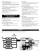
2. Make the line voltage connections as shown in Fig. 1.
3. Splice the leads with solderless connectors.
4. Feed the low voltage cad cell leads through the hole below the
low voltage terminal strip.
LOW VOLTAGE WIRING CONNECTIONS
• After mounting control, make low voltage connections to screw
terminals by connecting the cad cell leads to the F-F terminals
and thermostat leads to the T-T terminals.
CAUTION
Fire or explosion hazard can cause death
or property damage
• Be sure the combustion chamber is free of oil or oil vapor before
starting the system.
1. Make sure the system is powered. Check the circuit breaker or
fuse and close the system switch, if provided.
2. Open the shut off valve in the oil supply line.
3. Set thermostat to call for heat.
4. Push in (for 3 seconds) the red reset button and release it.
5. Burner should light and operate until a call for heat ends.