ICM325HN Head Pressure Control with Optional Heat Pump Override Temperature sensitive control regulates head pressure Installation, Operation & Application Guide For more information on our complete range of American-made products – plus wiring diagrams, troubleshooting tips and more, visit us at www.icmcontrols.
Table of Contents Specifications................................................................................................... Connections for ICM325HN at 120/208/240 VAC............................................. Connections for ICM325HN at 480 VAC........................................................... Connecting the Probe...................................................................................... Connections for Air Conditioning Only....................................................
Specifications Line voltage: 120, 208, 240, and 480 VAC Control voltage: 18-30 VAC Frequency: 50-60 Hz Operating temperature: -40ºF to +176ºF (-40°C to +75°C) Sensors: 10K ohms at 77°F (25°C) Heat pump override: 24 VAC N.C. or N.O. Note: A maximum of three sensors can be connected to the control. • Weight: 12 ounces (341 grams) Note: The ICM325HN should be applied to motors and equipment that have been designated by their respective manufacturers as capable of being speed controlled.
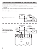
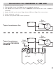
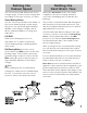
Connections for ICM325HN at 120/208/240 VAC 1. Remove power from system. 2. Field install a wire from Line 1 wire to Line 1 terminal. 3. Cut Line 2 wire; affix motor side to Motor 2 terminal and line side to Line 2 terminal. 4. Make 24 VAC, probe (see Page 4) and HP (see Page 5) connections. 5. Verify wiring is correct. 6. Power up system and check operation.
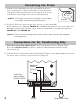
Connections for ICM325HN at 480 VAC 1. Remove power from system. 2. Field install a wire from Line 1 wire to Line 1 terminal. 3. Cut Line 2 wire; affix motor side to Motor 2 terminal and line side to Line 2 terminal. 4. Make 24 VAC, probe (see Page 4) and HP (see Page 5) connections. 5. Verify wiring is correct. 6. Power up system and check operation.
Connecting the Probe 1. Install the temperature probe several bends into the condenser. It can be attached to the U-bend or placed between the fins in the upper 1/3 of the condenser (see Page 9 for more information). Note: The response of the system can be fine tuned by repositioning the probe. Example 2. Connect the two wires from the sensor to the terminal . block where it is marked PROBE S1.
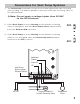
Connections for Heat Pump Systems 1. The Heat Pump terminals accept the 24 VAC signal from the reversing valve holding coil. Make a parallel connection from the reversing valve to the HP terminals. Note: Do not apply a voltage higher than 30 VAC to the HP terminals. 2. If the Heat Pump is in the Heating mode and the reversing valve is energized, then the Heat Pump Select jumper must be in the Default (N.O.) position. 3.
Mode of Operation Normal Function With probe temperatures above 100°F, the control applies full voltage to the motor. The green light is illuminated (full speed LED). With probe temperatures between 70°F and 100°F, the motor speed is proportional to the probe temperature. The yellow light is illuminated (variable speed LED). When the motor starts at temperatures between 70°F and 100°F, it will hard start for the length of time dictated by the hard start dial setting.
Setting the Cutout Speed The cutout speed dial adjusts the motor voltage range. Set the cutout voltage dial according to the type of motor you have. Sleeve Bearing Motors: Set the cutout speed dial to the middle of the sleeve bearing range. In this range, the motor can run down approximately 40-50% of the full line voltage, which allows sufficient RPMs for cooling and lubrication. CAUTION!: .
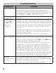
Troubleshooting Symptom Problem Unit fails to start The sensor may not be connected or it is defective. With the probe disconnected, use an ohmmeter to measure the resistance between the probe wires. It should match the chart in Appendix B (see Page 9). If you read an OPEN or SHORT, replace the sensor. Fuse and/or The unit has been miswired and may be permanently circuit blows damaged. The fan cycles Turn OFF the control circuit power (24 VAC).
Appendix A Appendix B Mounting a sensor into the condenser vs. mounting it on the liquid line Temperature vs. Probe Resistance When a sensor is mounted into the condenser, the control responds more rapidly to changes in head pressure than when it is mounted on the liquid line. This is especially true for high efficiency condensers. When the sensor is mounted on the liquid line, the control responds more slowly and the results can be a fan that cycles on and off.
ONE-YEAR LIMITED WARRANTY The Seller warrants its products against defects in material or workmanship for a period of one (1) year from the date of manufacture. The liability of the Seller is limited, at its option, to repair, replace or issue a non-case credit for the purchase prices of the goods which are provided to be defective.