THE TRANSCEIVER i7800 Instruction Manual A-6328H-1EX Printed in Japan © 2004 Icom Inc.
FOREWORD Congratulations! You are the owner of the world’s most advanced amateur HF/50 MHz transceiver— IC-7800. The IC-7800 is designed and built with Icom’s superior technology and craftsmanship. With proper care, this product should provide you with years of trouble-free operation. We would like to take a couple of moments of your time to thank you for making your IC-7800 your radio of choice, and hope you agree with Icom’s philosophy of “technology first.
PRECAUTIONS R WARNING HIGH VOLTAGE! NEVER attach an antenna or internal antenna connector during transmission. This may result in an electrical shock or burn. transmit. RWARNING! NEVER operate the transceiver with a headset or other audio accessories at high volume levels. Hearing experts advise against continuous high volume operation. If you experience a ringing in your ears, reduce the volume or discontinue use. AVOID placing the transceiver in excessively dusty environments or in direct sunlight.
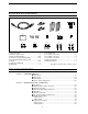
SUPPLIED ACCESSORIES w q r e t y u i o !0 !1 !2 !3 !4 q AC power cable* ………………………………… 1 w Antenna jumper cables …………………………… 2 e Rack mounting handles ……………………… 1 pair r Screws for rack mounting handles ………… 1 set t CF (Compact Flash) memory card ……………… 1 y Stands ………………………………………… 1 pair u Spare fuse (FGB 2 A) …………………………… 1 i RCA plugs ………………………………………… 2 o DC power plug …………………………………… 1 !0 2-conductor 1⁄8″ plugs …………………………… 3 !1 3-conductor 1⁄8″ plugs …………………………… 2 !2 3-conductor 1⁄4″ plugs ……
TABLE OF CONTENTS D Rear panel—2 ……………………………………………………… 2-6 ■ Linear amplifier connections …………………………………………… 2-7 D Connecting the IC-PW1 …………………………………………… 2-7 D Connecting a non-Icom linear amplifier …………………………… 2-7 ■ Transverter jack information …………………………………………… 2-8 ■ FSK and AFSK (SSTV) connections ………………………………… 2-8 ■ Microphone connector information …………………………………… 2-9 ■ Microphones (options) ………………………………………………… 2-9 D SM-20 ………………………………………………………………… 2-9 D HM-36 ………………………………………………………………… 2-9 ■ Accessory co
TABLE OF CONTENTS ■ ■ ■ ■ ■ ■ ■ Section 5 D Memory keyer screen …………………………………………………4-8 D Editing a memory keyer ………………………………………………4-9 D Contest number set mode …………………………………………4-10 D Keyer set mode ………………………………………………………4-11 Operating RTTY (FSK) ……………………………………………… 4-13 D Convenient functions for receive …………………………………4-14 D About RTTY reverse mode …………………………………………4-14 D Twin peak filter ………………………………………………………4-14 D Functions for the RTTY decoder indication ………………………4-15 D Setting the decoder threshold leve
TABLE OF CONTENTS ■ ■ ■ ■ ■ ■ Section 6 D DSP filter shape …………………………………………………… D Filter shape set mode ……………………………………………… Dualwatch operation ………………………………………………… Noise blanker ………………………………………………………… D NB set mode ………………………………………………………… Noise reduction ………………………………………………………… Dial lock function ……………………………………………………… Notch function ………………………………………………………… Digital selector ………………………………………………………… 5-14 5-14 5-16 5-17 5-17 5-18 5-18 5-19 5-19 FUNCTIONS FOR TRANSMIT ■ VOX function …………………………………………………………… D Using
TABLE OF CONTENTS Section 9 ■ Memory channel programming ……………………………………… D Programming in VFO mode ………………………………………… D Programming in memory mode …………………………………… ■ Frequency transferring ………………………………………………… D Transferring in VFO mode ………………………………………… D Transferring in memory mode ……………………………………… ■ Memory names ………………………………………………………… D Editing (programming) memory names …………………………… ■ Memory clearing ………………………………………………………… ■ Memo pads ……………………………………………………………… D Writing frequencies and operating modes into mem
TABLE OF CONTENTS ■ ■ ■ ■ ■ Section 13 D Load option set mode …………………………………………… File saving …………………………………………………………… File loading …………………………………………………………… Changing the file name ……………………………………………… Deleting a file ………………………………………………………… Formatting the CF card ……………………………………………… 12-22 12-23 12-24 12-25 12-26 12-26 MAINTENANCE ■ Troubleshooting ……………………………………………………… D Transceiver power ………………………………………………… D Transmit and receive ……………………………………………… D Scanning …………………………………………………………… D Display ………………………………………………
PANEL DESCRIPTION ■ ■ ■ ■ Section 1 Front panel ……………………………………………………………… 1-2 Rear panel ……………………………………………………………… 1-12 LCD display …………………………………………………………… 1-14 Screen menu arrangement …………………………………………… 1-15 1-1
1 PANEL DESCRIPTION ■ Front panel io !0 !1 !2 !3 q w e r t y u !4 !5 !6 !7 q POWER SWITCH [POWER] (p. 3-2) !8 r TIMER SWITCH [TIMER] (p. 11-4) ➥ Turns the sleep or daily timer function ON and OFF when pushed. Turn the internal power supply ON in advance. The internal power supply switch is located on the rear panel. (p. 3-2) • The [TIMER] indicator above this switch lights green when the timer is in use. ➥ Enters timer set mode when pushed for 1 sec. ➥ Push to turn the transceiver power ON.
PANEL DESCRIPTION i MIC GAIN CONTROL [MIC] Adjusts microphone input gain. !2 BREAK-IN DELAY CONTROL [DELAY] (p. 6-3) Adjusts the transmit-to-receive switching delay time for CW semi break-in operations. • The transmit audio tone in SSB, AM and FM modes can be adjusted independently in set mode. (p. 12-4) Long delay for slow speed keying ✔ How to set the microphone gain. Set the [MIC] control so that the ALC meter sometimes swings during normal voice transmission in SSB, AM or FM mode.
1 PANEL DESCRIPTION ■ Front panel (continued) @7 @8 @9 #0 #1 !9 @0 @1 @2 @3 @4 @5 @6 #2 #3 #4 @5 RF GAIN CONTROL [RF] (outer control; for MAIN band; p. 3-9) @6 RF GAIN CONTROL [RF] (outer control; for SUB band; p. 3-9) Adjusts the RF gain level. While rotating the RF gain control, noise may be heard. This comes from the DSP unit and does not indicate an equipment malfunction. !9 AGC CONTROL [AGC] (for MAIN band; p. 5-11) @0 AGC CONTROL [AGC] (for SUB band; p.
PANEL DESCRIPTION 1 ➥ Turns the speech compressor ON and OFF in SSB mode. (p. 6-5) ➥ Switches the narrow, middle or wide transmit filter when pushed for 1 sec. @9 MULTI-FUNCTION SWITCHES Push to select the functions indicated in the LCD display to the right of these switches. • Functions vary depending on the operating condition. ➥ Selects the antenna connector from ANT1, ANT2, ANT3 and ANT4 when pushed. (p. 10-2) ➥ Displays antenna selection memory when pushed for 1 sec.
1 PANEL DESCRIPTION ■ Front panel (continued) $1 $2 $3 $5 $7 $8 $4 $6 $9 #5 #6 #7 #8 #9 $0 %0 %1 #5 NOISE REDUCTION SWITCH [NR] (for MAIN band; p. 5-18) #6 NOISE REDUCTION SWITCH [NR] (for SUB band; p. 5-18) Push to switches the noise reduction ON and OFF. %2 %3 %4 %5 %6 $1 NOISE BLANKER SWITCH [NB] (for MAIN band; p. 5-17) $2 NOISE BLANKER SWITCH [NB] (for SUB band; p. 5-17) ➥ Switches the noise blanker ON and OFF when pushed.
PANEL DESCRIPTION $9 MEMORY UP/DOWN SWITCHES [Y]/[Z] (p. 8-2) Push to select the memory channel number for the selected readout. 1 %4 VOICE MEMORY PLAY BACK SWITCH [PLAY] (p. 7-4) ➥ Play back the previously recorded audio for the preset time period when pushed. ➥ Play back all of the previously recorded audio when pushed for 1 sec. • Memory channels can be selected both in VFO and memory modes.
1 PANEL DESCRIPTION ■ Front panel (continued) %7 %8 %9 ^0 ^1 ^2 ^3 ^4 ^5 ^6 ^7 ^8 ^9 &0 &1 &2 &4 %7 MEMO PAD-WRITE SWITCH [MP-W] (p. 8-7) Programs the selected readout frequency and operating mode into a memo pad. &5 &6 &8 &3 &9 &7 ^1 MEMO PAD-READ SWITCH [MP-R] (p. 8-7) Each push calls up a frequency and operating mode in a memo pad. The 5 (or 10) most recently programmed frequencies and operating modes can be recalled, starting from the most recent.
PANEL DESCRIPTION &2 AUTOMATIC TUNING SWITCH [AUTO TUNE] (for MAIN band) &3 AUTOMATIC TUNING SWITCH [AUTO TUNE] (for SUB band) Turns the automatic tuning function ON and OFF in CW and AM modes. ^6 NOTCH SWITCH [NOTCH] (for SUB band; p. 5-19) ^7 NOTCH SWITCH [NOTCH] (for MAIN band; p. 5-19) ➥ Switches the notch function between auto, manual and OFF in SSB and AM modes. ➥ Turns the manual notch function ON and OFF when pushed in CW, RTTY and PSK31 mode.
1 PANEL DESCRIPTION ■ Front panel (continued) *0 *1 *3 *4 *2 *5 *7 *8 *6 *9 (0 (1 (2 (3 (4 (5 (6 (7 (8 *0 RIT/∂TX CONTROL [RIT/∂TX] (pgs. 5-10, 6-4) Shifts the receive and/or transmit frequency without changing the transmit and/or receive frequency while the RIT and/or ∂TX functions are ON. PBT1 PBT2 • Rotate the control clockwise to increase the frequency, or rotate the control counterclockwise to decrease the frequency. • The shift frequency range is ±9.999 kHz in 1 Hz steps (or ±9.
PANEL DESCRIPTION 1 (2 RIT SWITCH [RIT] (p. 5-10) ➥ Turns the RIT function ON and OFF when pushed. *5 DIGITAL RF SELECTOR CONTROL [DIGI-SEL] (for MAIN band; p. 5-19) *6 DIGITAL RF SELECTOR CONTROL [DIGI-SEL] (for SUB band; p. 5-19) Adjusts the digital RF selector center frequency. • Use [RIT/∂TX] control to vary the RIT frequency. ➥ Adds the RIT shift frequency to the operating frequency when pushed for 1 sec. • The control can be used as the audio peak filter adjustment (p.
1 PANEL DESCRIPTION ■ Rear panel q w e r t y u i o !0 IN X-VERTER OUT OUT !1 IN RX ANT RX ANT B A I !2 ANT 3 ANT 2 ANT 1 ANT 4 AC !3 GND EXT-DISPLAY KEY BOARD RS-232C REMOTE #3 #2 #1 #0 S/P DIF OUT IN @9 @8 REF I/O 10MHz -10dBm @7 DC OUT EXT 15V MAX1A METER KEYPAD @6 @5 @4 @3 ACC 1 ACC 2 ACC 1 EXT-SP SUB MAIN @2 @1 @0 !9 !8 !7 !6 !5 !4 ALC ALC ADJ A !0 RECEIVE ANTENNA A OUT [RX ANT A– OUT] !1 RECEIVE ANTENNA A IN [RX ANT A– IN] Located between the transm
PANEL DESCRIPTION @7 REFERENCE SIGNAL INPUT/OUTPUT TERMINAL [REF I/O] Inputs/outputs a 10 MHz reference signal. !6 ACCESSORY SOCKET 1 A [ACC 1–A] !7 ACCESSORY SOCKET 2 A [ACC 2–A] !8 ACCESSORY SOCKET 1 B [ACC 1–B] !9 ACCESSORY SOCKET 2 B [ACC 2–B] Enable connection of external equipment such as a liner amplifier, an automatic antenna selector/tuner, TNC for data communications, etc. @8 S/P DIF INPUT TERMINAL [S/P DIF– IN] (p. 2-6) @9 S/P DIF OUTPUT TERMINAL [S/P DIF– OUT] (p.
1 PANEL DESCRIPTION ■ LCD display q w e tr y u i q w e rt y u o !1 !0 !2 !3 !4 !5 !8 !6 !7 !4 !5 !1 VFO/MEMORY CHANNEL INDICATOR (p. 3-3) Indicates the VFO mode or selected memory channel number. q BAND WIDTH INDICATOR (p. 5-12) Shows the passband width of the IF filter. w MODE INDICATOR Shows the selected mode. !2 IF FILTER INDICATOR Shows the selected IF filter number. e SHIFT FREQUENCY INDICATOR (p. 5-12) Shows the shift frequency of the IF filter.
PANEL DESCRIPTION 1 ■ Screen menu arrangement The following screens can be selected from the start up screen. Choose the desired screen using the following chart. Pushing [EXIT/SET] several times returns to the start up screen. See p. 12-3 for set mode arrangement. • PSK31 decoder screen (p. 4-21) • Spectrum scope screen (p. 5-2) • Memory channel screen (p. 8-3) • Voice recoder screen (p. 7-3) • Scan screen (VFO mode; p. 9-4) • Memory keyer screen (CW mode; p. 4-8) • Scan screen (Memory mode; p.
INSTALLATION AND CONNECTIONS ■ ■ ■ ■ ■ ■ ■ ■ ■ ■ ■ ■ ■ ■ ■ Section 2 Unpacking ……………………………………………………………… 2-2 Antenna jumper cable connection …………………………………… 2-2 Selecting a location …………………………………………………… 2-2 Rack mounting handle attachment …………………………………… 2-2 Grounding ……………………………………………………………… 2-3 Antenna connection …………………………………………………… 2-3 CF (Compact Flash) memory card …………………………………… 2-3 Required connections ………………………………………………… 2-4 D Front panel …………………………………………………………… 2-4 D Rear panel …………………………………………………
2 INSTALLATION AND CONNECTIONS ■ Unpacking After unpacking, immediately report any damage to the delivering carrier or dealer. Keep the shipping cartons. For a description and a diagram of accessory equipment included with the IC-7800, see ‘Supplied accessories’ on p. iii of this manual. ■ Antenna jumper cable connection Connect the supplied coaxial cable (terminated with BNC connectors) between [RX ANT A— IN] and [RX ANT A— OUT], and, [RX ANT B— IN] and [RX ANT B— OUT], respectively.
INSTALLATION AND CONNECTIONS 2 ■ Grounding To prevent electrical shock, television interference (TVI), broadcast interference (BCI) and other problems, ground the transceiver through the GROUND terminal on the rear panel. For best results, connect a heavy gauge wire or strap to a long earth-sunk copper rod. Make the distance between the [GND] terminal and ground as short as possible.
2 INSTALLATION AND CONNECTIONS ■ Required connections D Front panel CW key A straight key can be used when the internal electronic keyer is turned OFF in keyer set mode. (p. 4-12) Microphones (p. 2-9) Optional SM-20 Optional HM-36 D Rear panel Antenna 1, 2, 3, 4 (p. 2-3) [Example]: ANT1 for 1.8–18 MHz bands, ANT 2 for 21–28 bands ANT3 for 50 MHz band, ANT 4 for receive antenna A jumper cable is connected.
INSTALLATION AND CONNECTIONS ■ Advanced connections D Front panel Headphones CF (Compact Flash) memory card MIC The AFSK modulation signal can also be input from [MIC]. D Rear panel— 1 RX ANT A/B IN/OUT Connects an external preamp or lowpass filter. Antenna 1, 2, 3, 4 (p. 2-7) Connects a linear amplifier, antenna selector, etc. OUT IN X-VERTER IN OUT RX ANT RX ANT B A I ANT 3 ANT 2 ANT 1 ANT 4 AC GND EXT-DISPLAY KEY BOARD RS-232C REMOTE [REMOTE], [RS-232C] (p.
2 INSTALLATION AND CONNECTIONS D Rear panel— 2 Keyboard Connects an USB type PC keyboard directly for RTTY/PSK31 operation, as well as other text edit operation. External Display Connects a monitor display (at least 800×600 resolution) directory. Video output signal can be turned ON and OFF in set mode (p. 12-12) [DC OUT] Outputs regulated 14 V (approx.) DC for external equipment power supply. (max.
INSTALLATION AND CONNECTIONS 2 ■ Linear amplifier connections D Connecting the IC-PW1 To an antenna ACC-1 ACC cable (supplied with the IC-PW1) Remote control cable (supplied with the IC-PW1) Be sure to connect the cable to the 7-pin ACC 2 jack.
2 INSTALLATION AND CONNECTIONS ■ Transverter jack information When 2 to 13.8 V is applied to pin 6 of [ACC 2], the [XVERTER] connector is activated for transverter operation and the antenna connectors do not receive or transmit any signals. (p. 4-6) While receiving, [X-VERTER] connector can be activated as an input terminal from an external transverter. While transmitting, the [X-VERTER] connector outputs signals of the displayed frequency at –20 dBm (22 mV) as signals for the external transverter.
INSTALLATION AND CONNECTIONS 2 ■ Microphone connector information (Front panel view) i Main readout AF output (varies with [AF]/[BAL]) q Microphone input [MIC] Pin No. w u GND (Microphone ground) w +8 V DC output y GND (PTT ground) e Frequency up/down t PTT e r r Main readout squelch switch FUNCTION DESCRIPTION +8 V DC output Max.
2 INSTALLATION AND CONNECTIONS ■ Accessory connector information ACC 1 PIN No. NAME 2 4 5 1 8 3 6 7 4 1 6 2 1 RTTY Controls RTTY keying 2 GND Connects to ground. Connected in parallel with ACC 2 pin 2. 3 Input/output pin. SEND Goes to ground when transmitting. When grounded, transmits. Ground level : –0.5 V to 0.8 V Output current : Less than 20 mA Input current (Tx) : Less than 200 mA Connected in parallel with ACC 2 pin 3. 4 MOD 5 AF 6 SQLS 7 13.8 V 13.8 V output when power is ON.
BASIC OPERATIONS ■ ■ ■ ■ ■ ■ ■ ■ ■ ■ ■ ■ Section 3 When first applying power (CPU resetting) ………………………… 3-2 Initial settings …………………………………………………………… 3-2 Main/Sub band selection ……………………………………………… 3-3 Selecting VFO/memory mode ………………………………………… 3-3 Selecting an operating band …………………………………………… 3-4 D Using the band stacking registers ………………………………… 3-4 Frequency setting ……………………………………………………… 3-5 D Tuning with the main dial …………………………………………… 3-5 D Direct frequency entry with the keypad …………………………… 3-5 D Quic
3 BASIC OPERATIONS ■ When first applying power (CPU resetting) Before first applying power, make sure all connections required for your system are complete by referring to Section 2. Then, reset the transceiver using the following procedure. Resetting CLEARS all programmed contents in memory channels and returns programmed values in set mode to default values. q Turn the main power ON with [I/O] on the rear panel. [I/O] • The transceiver power is still OFF and the [POWER] indicator lights orange.
BASIC OPERATIONS 3 ■ Main/Sub band selection The IC-7800 has 2 bands, main and sub bands. The main band is displayed on the left hand side, and the sub band is displayed on the right hand side of the LCD. Some functions can only be accessed to the selected band and the transmission is only permitted for the main band (except the split frequency operation). ➥ Push [MAIN] to select the main band. [MAIN] [SUB] • The key backlight for [MAIN] lights. • Main band’s frequency readout highlighted.
3 BASIC OPERATIONS ■ Selecting an operating band The triple band stacking register provides 3 memories in one band. 3 sets of a frequency and operating mode on each band are automatically stored when used. Band keys If a band key is pushed once, the frequency and operating mode last used are called up. When the key is pushed again, another stored frequency and operating mode are called up. This function is convenient when you operate 3 operating modes on one band.
BASIC OPERATIONS 3 ■ Frequency setting The transceiver has several tuning methods for convenient frequency tuning. D Tuning with the main dial q Push the desired band key on the keypad 1–3 times. Band keys • 3 different frequencies can be selected on each band with the band key. • Push [MAIN] or [SUB] to select the band in advance. w Rotate the main dial to set the desired frequency in main band, rotate the sub dial to set the desired frequency in sub band.
3 BASIC OPERATIONS D Quick tuning step The operating frequency can be changed in kHz steps (0.1, 1, 5, 9, 10, 12.5, 20 or 25 kHz selectable) for quick tuning. q Push [TS] to turn the quick tuning function ON. • “Z” appears when the quick tuning function ON. w Rotate the main dial to change the frequency in programmed kHz steps. e Push [TS] again to turn OFF the indicator. r Rotate the main dial for normal tuning if desired.
BASIC OPERATIONS 3 D Selecting 1 Hz step The minimum tuning step of 1 Hz can be used for fine tuning. q Push [TS] to turn the quick tuning function OFF. w Push [TS] for 1 sec. to turn the 1 Hz tuning step ON and OFF. NOTE: 1 Hz tuning step activates for both main and sub bands simultaneously. Therefore, either [TS] can be used for the 1 Hz tuning step selection.
3 BASIC OPERATIONS ■ Operating mode selection SSB (USB/LSB), SSB data (USB data/LSB data), CW, CW reverse (CW-R), RTTY, RTTY reverse (RTTY-R), PSK, PSK reverse (PSK-R), AM, AM data, FM and FM data modes are available in the IC-7800. Select the desired operation mode as follows. To select a mode of operation, push the desired mode switch momentarily. Push the switch again to toggle between USB and LSB, CW and CW-R, RTTY/RTTYR and PSK/PSK-R, AM and FM, if necessary. Push the switch for 1 sec.
BASIC OPERATIONS ■ Volume setting 3 ➥ Rotate [AF] control clockwise to increase; counterclockwise to decrease the audio output level. • Set a suitable audio level. [AF] for main [AF] for sub Audio output increases Audio output decreases ■ RF gain adjustment [RF] for main ➥ Rotate [RF] control clockwise to increase; counterclockwise to decrease the receiver sensitivity.
3 BASIC OPERATIONS ■ Meter indication selection The S/RF meter indication, during transmit, can be selected from the following items as your desired. ➥ Push [METER] several times to select the desired item. Indicates the relative RF output power in watts. [METER] Indicates the VSWR over the transmission line. Signal strength level readout 9 5 +20 +40 1 5 S 0 10 50 100 150 200 ID readout 3 1.
BASIC OPERATIONS 3 D Meter type selection Total of 3 meter types are available in the IC-7800— Standard, Edgewise and Bar meters. Follow the instructions below for the meter type selection. q Push [EXIT/SET] several times to return to normal screen, if necessary. w Push [F-7•SET], then push [F-3•DISPLAY] to select display set mode. e Push [F-1•Y] or [F-2•Z] to select “Meter type (Normal Screen)” item. r Rotate main dial to select the desired meter type from “Standard,” “Edgewise” and “Bar.
3 BASIC OPERATIONS ■ Basic transmit operation Before transmitting, monitor your selected operating frequency to make sure transmitting won’t cause interference to other stations on the same frequency. It’s good Amateur practice to listen first, and then, even if nothing is heard, ask “is the frequency in use” once or twice, before you being operating on that frequency.
BASIC OPERATIONS 3 D Drive gain adjustment The drive gain can be activated for the all modes except SSB without speech compressor to adjust the amplifying gain at the drive stage. Before transmitting, monitor your selected operating frequency to make sure transmitting won’t cause interference to other stations on the same frequency. [METER] [DRIVE] q Push [METER] to select the ALC meter. w Push [PTT] (microphone; SSB with [COMP] ON, AM or FM), key down (CW) or push [TRANSMIT] (RTTY or PSK) to transmit.